


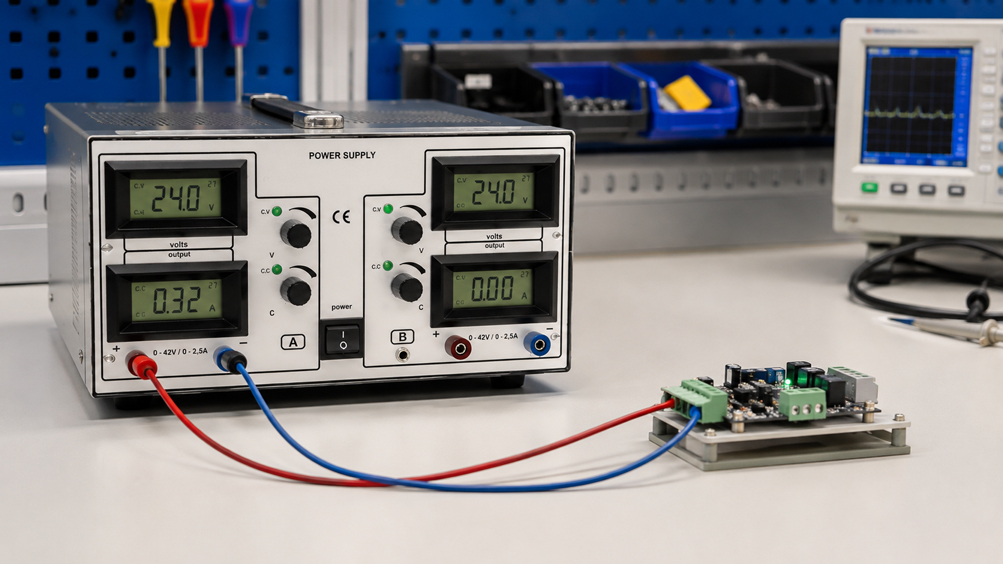
The laboratory power supply is set to:
24 V
and:
1,0 A current limit
.
However, after connecting a device under test, the power supply suddenly indicates only:
8,5 V
at:
1,0 A
.
Is the power supply defective?
In many cases, no. It has simply switched from constant-voltage operation (CV) to constant-current operation (CC).
This automatic transition is one of the most important functions of a regulated laboratory power supply.
During normal operation, the power supply first attempts to keep the set output voltage constant. However, if the connected load demands more current than permitted by the set current limit, the power supply reduces the output voltage until the current once again corresponds to the set limit.
In simplified terms:
CV: voltage is regulated, current results from the load
and:
CC: current is regulated, voltage results from the load
.
The transition from CV to CC is therefore normally not an error message, but a direct consequence of the load, the set voltage and the set current limit.
A specific example is the 2229.2 DC Voltage Regulator offered by ICS Schneider. The benchtop device has two adjustable DC voltage outputs, each with 0 … 40 VDC and 0 … 2,5 A, as well as automatic switching between CV and CC operating modes.
Additional solutions can be found under Laboratory Power Supplies and generally under Power Supplies.
Table of Contents
- What do CV and CC mean?
- How does constant-voltage operation work?
- How does constant-current operation work?
- When does the power supply switch from CV to CC?
- Calculating the CV/CC transition point
- Setting the current limit correctly
- How does the current limit protect the device under test?
- What happens in the event of a short circuit?
- Inrush current and capacitive loads
- Motors and high starting currents
- Considering voltage, current and power together
- Voltage drop across test leads
- Using CC as a diagnostic indication
- Typical error patterns
- Recommended procedure for initial commissioning
- Practical example: Testing a 24 V assembly
- 2229.2 DC Voltage Regulator at ICS Schneider
- Conclusion
- FAQ
What do CV and CC mean?
The two abbreviations stand for:
CV = Constant Voltage
and:
CC = Constant Current
In CV operation
the power supply regulates the:
output voltage
to the set value.
In CC operation
by contrast, the:
output current
is regulated to the set limit.
The key point is
CV and CC are not two completely separate operating modes that the user must manually select for every load. The actual regulation mode results from the voltage setting, current limit and connected load.
Example
Set values:
Uset = 24 V
ILimit = 1 A
If the load only draws
300 mA
the device remains in:
CV operation
If the load instead attempts
to draw more than:
1 A
the current limit becomes active.
The power supply switches to:
CC
How does constant-voltage operation work?
Constant-voltage operation is the typical mode when supplying electronic assemblies.
Example
The power supply is set to:
24 V
and:
2 A current limit
The device under test requires
0,5 A
The power supply then delivers approximately
24 V / 0,5 A
Important
The setting:
2 A
does not mean that the power supply continuously forces 2 A into the circuit.
The connected load determines
its current consumption according to its electrical characteristics.
For a resistive load
I = U / R
Example
At:
U = 24 V
and:
R = 48 Ω
the result is:
I = 24 V / 48 Ω = 0,5 A
Since 0,5 A is lower than the current limit of 2 A
the power supply remains in the:
CV range
How does constant-current operation work?
In CC operation, the connected load would draw more current at the set target voltage than permitted by the set current limit.
The power supply responds
by reducing the output voltage.
The regulator then attempts
I = ILimit
to maintain.
Example
Set values:
24 V
1 A
Connected resistive load
R = 10 Ω
Without current limiting, at 24 V the current would be
I = 24 V / 10 Ω = 2,4 A
However, only
1 A
is permitted.
The power supply therefore reduces the voltage to approximately
U = I × R
U = 1 A × 10 Ω = 10 V
The resulting operating point is approximately
10 V / 1 A / CC
The set 24 V still remains relevant
However, it only represents the maximum desired output voltage. Due to the active current limit, it is not reached with this load.
When does the power supply switch from CV to CC?
The transition occurs exactly when the current required for the desired output voltage reaches the set current limit.
For a resistive load
I = U / R
The transition point is reached when
I = ILimit
This results in
Rlimit = Uset / ILimit
For load resistances above this value
the device operates in the:
CV range
For lower load resistances
the current limit becomes active:
CC range
Calculating the CV/CC transition point
A power supply is set to:
20 V
and:
2 A
The limiting resistance is
Rlimit = 20 V / 2 A = 10 Ω
| Load | Current at 20 V | Operating mode | Approximate output |
|---|---|---|---|
| 40 Ω | 0,5 A | CV | 20 V / 0,5 A |
| 20 Ω | 1,0 A | CV | 20 V / 1,0 A |
| 10 Ω | 2,0 A | Transition range | 20 V / 2,0 A |
| 5 Ω | 4,0 A theoretical | CC | approx. 10 V / 2,0 A |
| 2 Ω | 10 A theoretical | CC | approx. 4 V / 2,0 A |
Setting the current limit correctly
The current limit should not automatically be set to the maximum possible output current of the power supply.
Instead, the following should be taken into account
- normal operating current of the device under test,
- permissible maximum current,
- inrush current,
- conductor cross-section,
- current-carrying capacity of connectors,
- current-carrying capacity of sensitive components.
Especially during initial commissioning
a deliberately limited output current can help to reduce damage caused by:
- short circuits,
- incorrect wiring,
- reverse-polarity components,
- solder bridges,
- defective semiconductors
.
However, the limit must not be set too low either
If a circuit requires, for example, a brief current of:
800 mA
during startup and the current limit is:
300 mA
the output voltage may collapse so far that the circuit does not start at all.
How does the current limit protect the device under test?
The current limit prevents the power supply from automatically providing its entire available output current in the event of an overload.
In the event of a fault
the voltage is reduced as soon as:
ILimit
is reached.
This can limit the electrical power
because:
P = U × I
This can help
- protect PCB tracks,
- limit component damage,
- investigate faults in a more controlled manner,
- detect implausibly high current consumption at an early stage.
Important
An adjustable current limit does not replace the fuses and protective measures required for the device under test.
What happens in the event of a short circuit?
For an idealized short circuit:
R ≈ 0 Ω
With a regulated and short-circuit-proof power supply
the device enters current limiting.
The output voltage then drops
significantly, while the output current is limited to the permissible or set value.
The 2229.2
is explicitly described by ICS as:
short-circuit-proof
ICS additionally specifies
a:
temperature monitoring function
for the device.
Nevertheless, for practical use
an intentional short circuit should only be used as an adjustment or test procedure if this method is specifically provided for in the operating instructions of the particular device.
Inrush current and capacitive loads
A brief transition into CC operation does not automatically indicate a fault.
Typical example
An electronic assembly contains large input capacitors.
Immediately after switching on
these capacitors are discharged and can cause a high charging current.
A typical sequence can be
Switch on → CC → capacitors charge → current decreases → CV
This behavior is plausible
if subsequently:
- the target voltage is reached,
- the current drops to the expected operating value,
- the power supply operates stably in CV mode.
By contrast, it is problematic
if the device remains permanently in CC and the target voltage is not reached.
Motors and high starting currents
DC motors often require significantly more current during startup than during steady-state operation.
If the current limit is set too low
the power supply switches to CC and reduces the voltage.
This can create an unfavorable condition
Motor stopped → high current demand → CC → voltage decreases → starting torque insufficient → motor remains stopped
For motors, the following must therefore be taken into account
- rated voltage,
- rated current,
- starting current,
- stall current,
- required power
.
Considering voltage, current and power together
For electrical loads:
P = U × I
Example
24 V × 2 A = 48 W
A power supply therefore must
not only provide the required:
- voltage range,
- current range
.
The required output power must also be suitable for the application.
For the 2229.2
ICS specifies for each of the two outputs:
0 … 40 VDC / 0 … 2,5 A
The specified output power is
2 × 100 W
Voltage drop across test leads
Resistance is present between the power supply and the device under test due to:
- test leads,
- plugs,
- terminals,
- contact points.
The voltage drop is
Ulead = I × Rlead
Example
Total lead resistance:
0,25 Ω
Current:
2 A
This results in
Ulead = 0,5 V
With 24 V at the power supply
only approximately:
23,5 V
is therefore available at the device under test.
For this reason, it can be useful
to additionally check the voltage directly at the terminals of the device under test.
Using CC as a diagnostic indication
The CC state can be very useful during service and troubleshooting.
Example
An assembly is expected to draw:
250 mA
normally at:
24 V
However, after switching on, the power supply continuously indicates
4,8 V / 1 A / CC
This makes it clear
that the target voltage is not being reached because the assembly already reaches the set current limit at a low voltage.
Possible causes
- short circuit,
- incorrect polarity,
- defective semiconductor,
- incorrect wiring,
- current limit set too low.
The correct response is not automatically
Increase the current limit
Instead, first
determine the cause of CC operation
Typical errors during CV/CC operation
| Observation | Possible cause | Recommended check |
|---|---|---|
| Power supply operates in CC instead of CV | Current limit reached | Compare current consumption with the set limit |
| Output voltage is lower than the set value | Current regulation is active | Check load and current limit |
| Device under test does not start | Current limit too low for the inrush current | Check inrush current requirement |
| Brief CC operation during startup | Charging of input capacitors | Check whether CV is subsequently reached |
| Continuous CC operation | Overload, short circuit or current limit set too low | Check device under test and settings |
| Electronics restart cyclically | Current limiting prevents complete startup | Observe voltage and current profile |
| Motor does not start | Starting current exceeds current limit | Check starting current and power-supply capability |
| Voltage at the device under test is lower than at the power supply | Lead and contact resistances | Measure voltage directly at the device under test |
| Power supply becomes very warm | High continuous load | Check output power and operating conditions |
Recommended procedure for initial commissioning
- Determine the rated voltage: Check the data sheet or circuit documentation of the device under test.
- Determine the normal operating current: Estimate the expected current demand.
- Take inrush current into account: Consider capacitors, motors and other dynamic loads.
- Check polarity: Clearly verify positive and negative.
- Set the output voltage: Do not exceed the permissible voltage of the device under test.
- Set the current limit: Select an appropriate limit for the specific application.
- Check the test leads: Use sufficient conductor cross-section and secure connections.
- Connect the device under test: Check the wiring again before switching on.
- Activate the output: Observe voltage and current.
- Observe the CV/CC state: Check the regulation mode immediately after switching on.
- Evaluate brief CC operation: Distinguish inrush current from continuous overcurrent.
- Do not automatically increase the limit during continuous CC operation: Investigate the cause.
- Check the voltage at the device under test: Take lead losses into account.
- Check the power consumption:
P = U × I. - Observe temperature development: Check the device under test, leads and power supply.
Practical example: Testing a 24 V assembly
A repaired industrial electronic assembly is to be switched on for the first time after several components have been replaced.
Rated voltage
24 VDC
Normal operating current
approx. 300 mA
Expected brief inrush current
approx. 600 mA
Step 1
One output of the 2229.2 is set to:
24 V
Step 2
The current limit is selected so that a plausible inrush current is possible, while the maximum available output current is not immediately provided in the event of a fault.
Step 3
When switched on, the current briefly reaches the set limit.
The device briefly operates in the
CC range
Subsequently
the output voltage rises to:
24 V
and the current falls to:
310 mA
The operating point is now in the
CV range
Interpretation
The brief CC state is consistent with the expected inrush current.
Another case
The power supply remains continuously at:
5 V / current limit active
In that case, the following should be checked
- short circuit,
- reverse polarity,
- wiring error,
- defective components,
- correct current-limit setting.
Result
The transition between CV and CC is not only a protective function, but also provides immediate information about the electrical operating point of the device under test.
2229.2 DC Voltage Regulator at ICS Schneider
A suitable specific device for the CV/CC applications described here is the:
The device is directly listed as a product by ICS Schneider
and has two independently usable regulated DC voltage outputs.
ICS specifies the following key data
- 2 × 0 … 40 VDC output voltage,
- 2 × 0 … 2,5 A output current,
- 2 × 100 W output power,
- linear regulator,
- automatic CV/CC operating-mode switching,
- voltage regulation,
- current regulation,
- short-circuit protection,
- temperature monitoring,
- digital displays,
- galvanically isolated and floating outputs,
- 4 mm equipment terminals, screw and plug connection.
Particularly important for this article
is the function explicitly specified by ICS:
automatic CV/CC operating-mode switching
This makes the 2229.2 suitable, for example, for
- development of electronic assemblies,
- service and troubleshooting,
- controlled initial commissioning,
- supplying sensors and control components,
- laboratory and training setups.
Two outputs provide additional flexibility
For circuits with two separate supply voltages, both regulated outputs can be used.
Important
The permissible electrical operating conditions and the specific connection arrangement must comply with the technical documentation of the device.
Conclusion
CV and CC describe two regulation states of a regulated DC power supply.
In CV operation
Voltage constant → load determines current
In CC operation
Current limited → output voltage is reduced
The transition occurs
when the current demand of the load reaches the set current limit.
For a resistive load, the limit can be calculated using
Rlimit = Uset / ILimit
Current limiting is particularly valuable
for:
- initial commissioning,
- service work,
- troubleshooting,
- sensitive electronics,
- defined current tests.
Unexpected continuous CC operation
is a diagnostic indication and should not automatically be eliminated by increasing the current limit.
With the 2229.2, ICS offers a specifically listed device
with:
2 × 0 … 40 VDC + 2 × 0 … 2,5 A + automatic CV/CC switching
For practical applications
Determine rated voltage → check normal and maximum current demand → set voltage → select appropriate current limit → check polarity and leads → connect device under test → observe voltage, current and CV/CC state → distinguish brief inrush current from continuous overcurrent → investigate the cause of unexpected CC operation → only then change the settings.
FAQ: CV and CC on a Laboratory Power Supply
What does CV mean?
CV stands for Constant Voltage. The power supply keeps the set output voltage constant as long as the current limit is not reached.
What does CC mean?
CC stands for Constant Current. The power supply limits the current and, if necessary, reduces the output voltage accordingly.
Why does a laboratory power supply switch from CV to CC?
Because the load would draw more current at the desired voltage than permitted by the set current limit.
Is CC an error message?
No. CC initially only describes the current regulation state.
Why does the voltage decrease in CC operation?
The voltage is reduced until the output current no longer exceeds the set limit.
What does a setting of 24 V and 1 A mean?
The power supply attempts to output 24 V. If the load requires less than 1 A, it operates in CV mode. If the load would draw more than 1 A, the current is limited.
How is the CV/CC transition point calculated?
For a resistive load using Rlimit = Uset / ILimit.
Why does the power supply briefly enter CC when switched on?
Increased inrush current, for example from discharged capacitors, can briefly reach the current limit.
Is brief CC operation during startup a problem?
Not necessarily. The decisive factor is whether the target voltage is subsequently reached and a plausible operating current is established.
Why does my electronics not start with a low current limit?
The required inrush current may be above the set limit. The output voltage may then not rise sufficiently.
Should I simply increase the current limit during continuous CC operation?
No. It should first be clarified whether overload, short circuit, wiring error or an actually too-low current limit is the cause.
What happens in the event of a short circuit?
With a suitably designed power supply with current limiting, the output voltage drops significantly while the current is limited.
Is the 2229.2 short-circuit-proof?
Yes. ICS explicitly describes the 2229.2 as short-circuit-proof.
Does the 2229.2 provide CV and CC operation?
Yes. ICS specifies automatic CV/CC operating-mode switching as well as voltage and current regulation.
What output voltage does the 2229.2 provide?
The device has two outputs, each with 0 … 40 VDC.
What output current does the 2229.2 provide?
ICS specifies 0 … 2,5 A for each of the two outputs.
What output power does the 2229.2 provide?
ICS specifies 2 × 100 W.
Does the 2229.2 have digital displays?
Yes. The device is explicitly described with digital displays on the ICS product page.
Which regulation technology does the 2229.2 use?
ICS describes the device as a linear regulator.
Are the outputs galvanically isolated?
ICS specifies galvanic isolation between input and output as well as floating outputs.
Which output connections does the 2229.2 have?
ICS specifies 4 mm equipment terminals that can be used as screw or plug connections.
Where can I find the 2229.2 at ICS Schneider?
Further information can be found under 2229.2 DC Voltage Regulator at ICS Schneider.
Where can I find additional laboratory power supplies at ICS Schneider?
An overview can be found under Laboratory Power Supplies at ICS Schneider.