


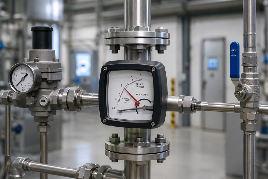
A variable area flowmeter can indicate an apparently clear value in a gas line and still deviate significantly from the actually expected flow rate. The cause is often not a defective measuring instrument, but rather that the flowmeter was sized for different pressure or temperature conditions than those actually encountered later in the process.
This relationship is particularly important for gases because their density depends strongly on pressure and temperature. A float reacts directly to the density of the flowing medium. If the process conditions change, the relationship between float position and flow rate therefore changes as well.
A scale indication such as:
0 … 10 m³/h
is therefore only fully meaningful for a gas if it is also known for which:
- gas,
- pressure level,
- temperature level,
- reference or standard condition
the scale was designed.
For the correct sizing of a variable area flowmeter for gases, gas type, operating pressure, gas temperature and the desired flow unit must therefore always be considered together.
A suitable industrial instrument is the Siemens SITRANS FVA250 variable area flowmeter offered by ICS Schneider. The instrument is suitable for liquids, gases and steam and, depending on the version, can be configured for demanding process conditions with high pressures and temperatures.
Additional solutions can be found under Flow Measurement Technology and specifically under Variable Area Flowmeters at ICS Schneider.
Table of Contents
- How does a variable area flowmeter work?
- Why are gases particularly critical when sizing the instrument?
- Distinguishing operating volume and standard volume
- What does Nm³/h mean?
- Why are the scale reference conditions decisive?
- Why must absolute pressure always be used?
- Why must gas temperature be entered in Kelvin?
- How pressure and temperature change gas density
- Do not confuse two different conversions
- Correcting a variable area flowmeter scale for changed pressure and temperature
- Converting operating volume to standard volume
- What happens when using a different gas?
- Practical example of pressure and temperature correction
- Pressure regulator upstream or downstream of the flowmeter?
- Considering the pressure loss of the variable area flowmeter
- Mounting position and flow direction
- Pulsation and fluctuating indication with gases
- Selecting the correct measuring range
- Typical error patterns
- Which data are required for sizing?
- Practical case: Nitrogen supply at elevated pressure
- Siemens SITRANS FVA250 at ICS Schneider
- Conclusion
- FAQ
How does a variable area flowmeter work?
A variable area flowmeter operates according to the principle of a variable flow cross-section. The medium flows through a measuring section whose free flow area changes with the position of the float.
The flowing medium lifts the float until an equilibrium is established between the acting forces.
In simplified terms, these include:
- the weight of the float,
- buoyancy,
- flow force.
As the flow rate increases, the float moves further upward or into a region with a larger free flow cross-section.
Its position then corresponds to a specific flow rate.
With the SITRANS FVA250
the movement of the float is transmitted to the external indicator via a magnetic system.
This enables direct local flow indication even with an all-metal design.
Why are gases particularly critical when sizing the instrument?
With a liquid, density usually changes only comparatively little as a result of moderate pressure variations.
With a gas, this is different.
Gas density depends substantially on:
- absolute pressure,
- absolute temperature,
- gas type
.
If the pressure increases
the gas becomes denser.
If the temperature increases
the gas becomes less dense at the same pressure.
For the float, this means
that the same float position under changed process conditions does not necessarily correspond to the same actual volumetric flow rate.
For gases, the following question must therefore always be asked
For which gas density was this scale designed?
Distinguishing operating volume and standard volume
With gas flow rates, at least two different quantities must be distinguished.
Operating volumetric flow
The operating volumetric flow describes the actual volume occupied by the gas under the current process conditions.
A typical unit is:
m³/h operating conditions
Standard volumetric flow
With standard volumetric flow, the same quantity of gas is converted back to defined reference conditions.
A typical unit is:
Nm³/h
This means
one cubic metre of gas at high pressure contains considerably more gas mass or amount of substance than one cubic metre of the same gas at atmospheric pressure.
Therefore, for example
1 m³/h operating volume
and:
1 Nm³/h
can describe completely different gas flow rates in the same system.
What does Nm³/h mean?
The “N” in Nm³/h indicates that the gas volumetric flow has been referenced to defined standard conditions.
Typical reference conditions are, for example
TN = 0 °C = 273,15 K
and:
pN = 1,01325 bar abs
However, caution is required
The specific reference condition must always be stated or checked.
In different technical applications, for example:
- 15 °C,
- 20 °C,
- other reference pressures
may also be used.
Therefore, a value such as
100 Nm³/h
is technically only fully defined when the underlying reference condition is also known.
Why are the scale reference conditions decisive?
A direct flow scale of a variable area flowmeter is designed for specific medium and operating-condition data.
For the SITRANS FVA250, Siemens specifies the following reference data for gas measuring ranges
- gas density:
1,293 kg/m³, - temperature:
0 °C, - viscosity:
0,0181 mPa·s, - gauge pressure:
pe = 0 bar.
These values clearly demonstrate
that a specified gas measuring range must not be considered independently of:
density + pressure + temperature + gas type
.
For a specific application
the instrument can therefore be configured with a product scale matched to the application.
This is generally preferable
if the operating conditions are already known when the instrument is ordered.
A correctly configured scale significantly reduces subsequent conversion errors.
Why must absolute pressure always be used?
One of the most common errors in gas conversions is using gauge pressure instead of absolute pressure.
For example, a pressure gauge indicates
5 bar
.
This normally means
5 bar gauge pressure
For gas-state calculations, however, the following is required
pabs
As an approximation
pabs = pe + patm
At an atmospheric pressure of approximately 1,013 bar, this gives
5 bar(g) ≈ 6,013 bar(a)
A calculation using only 5 bar
would therefore result in a systematic error.
Basic rule
Gas conversions are performed using absolute pressure.
Why must gas temperature be entered in Kelvin?
Temperature must also not simply be entered in degrees Celsius in a gas equation.
Absolute temperature is used
in Kelvin:
T [K] = t [°C] + 273,15
Example
20 °C = 293,15 K
and
50 °C = 323,15 K
Why is this important?
A calculation using:
20 / 0
for 20 °C compared with 0 °C would not be physically meaningful.
Using Kelvin, by contrast, allows the ratio of absolute temperatures to be represented correctly.
How pressure and temperature change gas density
For an approximately ideal gas:
ρ ∝ p / T
Gas density therefore increases
when:
- absolute pressure increases,
- temperature decreases.
Gas density decreases
when:
- absolute pressure decreases,
- temperature increases.
This relationship directly influences
the forces acting on the float.
For the same gas
the density can be approximately compared using:
ρ2 / ρ1 ≈ (p2 / p1) × (T1 / T2)
.
At high pressures
real gas behavior can increasingly deviate from the ideal gas equation.
In this case, the:
compressibility factor Z
may also need to be taken into account.
Do not confuse two different conversions
With variable area flowmeters, two different calculations are often confused with one another.
1. State conversion of a gas volume
Here, an already known actual volumetric flow is converted from one pressure and temperature level to another.
The gas equation forms the basis for this calculation.
2. Correction of a variable area flowmeter scale
Here, it must be taken into account that the gas density itself influences the position of the float.
For this reason, the approximate correction involves:
a square-root relationship
.
This means
The simple standard-volume equation must not be used directly as a correction formula for an unchanged variable area flowmeter scale.
Correcting a variable area flowmeter scale for changed pressure and temperature
If the same gas is used and an existing variable area flowmeter scale is referenced to different pressure and temperature conditions, an approximate correction can be made.
For an indication scaled to standard or reference volume, the following may approximately apply
Qcorr ≈ Qindication × √[(pB,abs / pRef,abs) × (TRef / TB)]
Where
Qindication= indicated flow rate,pB,abs= actual absolute pressure at the measuring instrument,pRef,abs= reference absolute pressure of the scale,TB= actual gas temperature in Kelvin,TRef= reference temperature in Kelvin.
Important
This relationship is a technical approximation.
For exact sizing, the following may additionally be relevant:
- gas type,
- float density,
- viscosity,
- Reynolds number,
- compressibility factor,
- specific measuring tube and float geometry.
For new sizing
a factory scale designed for the actual process conditions is therefore preferable to a subsequent approximate correction.
Converting operating volume to standard volume
If the actual operating volumetric flow is already known, the pure state conversion is performed differently.
For an idealized gas, the following approximately applies
QN = QB × (pB,abs / pN,abs) × (TN / TB)
For real gas behavior, the following can additionally apply
QN = QB × (pB,abs / pN,abs) × (TN / TB) × (ZN / ZB)
This equation answers the question
What volume would the same quantity of gas occupy under standard conditions?
It does not directly answer the question
How must an incorrectly scaled variable area flowmeter indication be corrected?
What happens when using a different gas?
A variable area flowmeter scale depends not only on pressure and temperature, but also on the gas being used.
The main reason
is the different gas density.
Examples
The densities of:
- hydrogen,
- helium,
- nitrogen,
- air,
- argon,
- carbon dioxide
differ significantly.
A scale designed for air
therefore cannot be used without verification for:
CO₂
or:
hydrogen
.
As an approximate estimate
a density correction using a square-root relationship can be used under comparable operating conditions.
For reliable instrument sizing
however, the actual gas should already be specified during the sizing process.
Practical example of pressure and temperature correction
An existing variable area flowmeter has a gas scale referenced to approximately 0 °C and atmospheric pressure. The same gas is later to be used at an elevated operating pressure.
Reference conditions
pRef,abs = 1,013 bar
TRef = 273,15 K
Actual operating conditions
Gauge pressure:
pe = 2,0 bar
The absolute pressure is therefore approximately
pB,abs = 3,013 bar
Gas temperature
20 °C = 293,15 K
Indicated scale value
Qindication = 6,0 m³/h
Approximate correction factor
K ≈ √[(3,013 / 1,013) × (273,15 / 293,15)]
This gives approximately
K ≈ 1,67
The corrected referenced flow rate is therefore approximately
Qcorr ≈ 6,0 × 1,67 ≈ 10,0 m³/h
The key finding
An identical scale reading at atmospheric pressure and at 2 bar gauge pressure does not automatically represent the same quantity of gas.
For an actual measuring point
the final calculation should be performed using the actual:
- scale conditions,
- gas data,
- process conditions,
- instrument data
.
Pressure regulator upstream or downstream of the flowmeter?
In gas supply systems, a pressure regulator or control valve is often located in the immediate vicinity of the variable area flowmeter.
Its position is important
because it determines which pressure actually exists:
inside the measuring tube
.
A flowmeter upstream of a throttling valve
can, for example, operate at a significantly higher pressure than an instrument installed downstream of the pressure regulator.
For sizing, it is therefore not sufficient
to know only the cylinder pressure or compressor pressure.
What is required
is the actual operating pressure:
at the variable area flowmeter
With fluctuating backpressure
the gas density at the measuring instrument can also change.
This can cause the indication to fluctuate or become systematically affected.
Considering the pressure loss of the variable area flowmeter
A variable area flowmeter also causes a pressure loss.
For gases
the supply pressure alone is therefore not relevant.
It must be ensured
that the available differential pressure is sufficient for:
- the measuring instrument,
- the piping,
- the valves,
- downstream consumers
.
For the SITRANS FVA250
Siemens specifies as a boundary condition that the minimum operating pressure should be greater than twice the respective pressure loss.
At very low gas pressures
this point can therefore already become relevant during instrument selection.
Mounting position and flow direction
The classic variable area principle uses gravity as part of the force equilibrium.
For the SITRANS FVA250, the specified mounting position is
vertical
with flow direction
from bottom to top
.
An incorrect mounting position changes the force balance and can result in an incorrect indication.
During installation, the following should also be ensured
- mechanical pipe stresses are avoided,
- vibrations are reduced,
- process connections are correctly aligned
.
Pulsation and fluctuating indication with gases
Gas lines can exhibit pronounced pressure and flow fluctuations due to compressors, regulators or rapidly switching valves.
This can cause the float to
- oscillate,
- jump,
- fail to reach a stable position.
For the SITRANS FVA250, Siemens generally recommends damping for gas measurements
or particularly where pressure surges, turbulence or other instabilities occur.
A strongly fluctuating indication
should therefore not immediately be interpreted as:
a measuring instrument error
Instead, it should first be checked
- whether the gas pressure is stable,
- whether the control valve is oscillating,
- whether pulsations are present,
- whether the flow is being increased slowly.
Selecting the correct measuring range
A variable area flowmeter should not be selected solely according to the maximum possible gas flow rate.
The normal operating range
should use a sufficiently readable part of the scale.
For the SITRANS FVA250
Siemens specifies a measuring range turndown of:
1:10
Example
If an application normally requires:
8 … 10 Nm³/h
a measuring instrument with:
0 … 100 Nm³/h
is unnecessarily oversized in many cases.
A more suitable scale
improves:
- readability,
- resolution,
- detection of small flow changes.
Nevertheless, some reserve is required
for:
- maximum operation,
- process fluctuations,
- startup conditions.
Typical errors with variable area flowmeters for gases
| Observation | Possible cause | Recommended check |
|---|---|---|
| Indication does not match expected gas consumption | Scale designed for different pressure or temperature conditions | Compare scale reference conditions with operating data |
| Measured value changes after increasing line pressure | Changed gas density | Check absolute pressure and required correction |
| Standard volume and operating volume are confused | Unclear flow unit | Determine the reference condition of the unit |
| Conversion produces clearly incorrect values | Gauge pressure used instead of absolute pressure | Take pabs = pe + patm into account |
| Temperature correction is implausible | Degrees Celsius entered directly into the ratio | Convert temperature to Kelvin |
| Instrument was designed for air but is measuring a different gas | Different gas density and viscosity | Recalculate for the gas type or redesign the scale |
| Float fluctuates strongly | Pulsating gas flow or pressure fluctuations | Check pressure regulation and damping |
| Float remains unstable | Operating pressure too low or unfavorable flow conditions | Check pressure loss and operating pressure |
| Indication is constantly shifted | Incorrect reference conditions | Compare scaling data with the actual process |
| Flow indication is correct only at one particular operating pressure | Direct-reading scale was designed for exactly this pressure | Check the application data used for the original sizing |
| Indication remains at the lower end of the scale | Measuring range selected too large | Consider a smaller measuring range |
Which data are required for sizing?
For reliable sizing of a variable area flowmeter for gases, the process data should be specified as completely as possible.
1. Gas type
For example:
- air,
- nitrogen,
- argon,
- carbon dioxide,
- hydrogen,
- natural gas,
- gas mixture.
2. Required flow range
For example:
2 … 20 Nm³/h
3. Required flow unit
It must be defined whether the indication is to show, for example:
- l/h,
- m³/h operating conditions,
- Nl/min,
- Nm³/h
.
4. Reference condition
For standard or reference volume units, the temperature and pressure of the reference condition must be defined.
5. Operating pressure at the measuring instrument
What matters is:
pressure directly at the measuring point
and not merely the pressure of the upstream supply.
6. Gas temperature
The following should be specified:
- normal temperature,
- minimum temperature,
- maximum temperature
.
7. Process connection and nominal size
These must match the piping and the required measuring range.
8. Materials
The wetted materials must be compatible with the gas.
9. Process dynamics
The following should be taken into account:
- pulsations,
- rapid valve movements,
- compressors,
- strongly changing backpressure.
10. Signal transmission
If the flow rate is not only to be read locally, it must be clarified whether:
- limit switches,
- transmitters,
- electrical remote transmission
are required.
Practical case: Nitrogen supply at elevated pressure
In a production plant, nitrogen is to be distributed to several consumers. The existing variable area flowmeter was originally designed for gas pressure close to atmospheric pressure. After a modification to the plant, however, the measuring point is operated downstream of a pressure regulator at a significantly higher pressure.
The operator observes
that the previously familiar scale values no longer correspond to the actual nitrogen consumption.
During the analysis, the following data are first recorded
- gas type: nitrogen,
- required standard volumetric flow,
- operating pressure at the flowmeter,
- gas temperature,
- reference conditions of the existing scale.
The analysis shows
that the original scale was designed for a significantly lower gas density.
The higher gas density under the new operating conditions
changes the force equilibrium at the float and therefore the relationship between:
float position ↔ gas flow rate
Simply using the old scale value
is therefore not permissible.
For permanent operation of the system
the variable area flowmeter is sized to match:
- nitrogen,
- actual operating pressure,
- actual gas temperature,
- required standard volumetric flow unit
.
Result
With application-specific scaling, the operator can subsequently read the required gas flow directly without having to perform a manual pressure and temperature correction for every measured value.
Siemens SITRANS FVA250 at ICS Schneider
For industrial gas applications, ICS Schneider offers the:
Siemens SITRANS FVA250 variable area flowmeter
The FVA250 operates according to the variable area principle
and is suitable for:
- liquids,
- gases,
- steam.
ICS specifies, among other things, the following features
- robust all-metal design,
- impact-resistant housing cover,
- use at high pressures and temperatures,
- suitability for corrosive and flammable media depending on the version,
- product and percentage scales,
- contamination-resistant float guide,
- optional heating or cooling jacket,
- optional transmitter,
- optional limit switches.
Particularly relevant for gas flow measurements
is the possibility of adapting the scale to the specific application.
For the reference measuring-range data for gases, Siemens specifies
ρ = 1,293 kg/m³
at:
0 °C
and:
pe = 0 bar
The measuring range turndown is
1:10
For gases, Siemens specifies a measuring accuracy of
±2,0 % according to VDI/VDE 3513-2 at qG = 50 %
The specified mounting position is
vertical / flow from bottom to top
Depending on the version
different:
- nominal sizes,
- pressure ratings,
- materials,
- temperature ranges,
- measuring ranges
are available.
This makes the FVA250 particularly suitable
for industrial gas flow measurements where:
gas type + operating pressure + temperature + required scale reference
are to be taken into account during the sizing process.
Conclusion
When sizing a variable area flowmeter for gases, it is not sufficient to know only the required flow range. Since gas density depends directly on pressure, temperature and gas type, these parameters must already be taken into account when sizing the measuring instrument.
Operating volume and standard volume are different quantities
m³/h operating conditions ≠ Nm³/h
The reference condition must be clearly defined
In particular, the reference temperature and reference pressure form part of every clearly defined standard volumetric flow value.
Absolute pressure is decisive for pressure calculations
pabs = pe + patm
Temperatures must be entered as absolute values
T [K] = t [°C] + 273,15
The normal gas-state conversion must not be confused with correcting the variable area flowmeter scale
The float position itself depends on gas density. This is why a square-root relationship appears in scaling or approximate correction.
For new measuring points, an application-specific product scale is the better solution
If the gas type, operating pressure and temperature are known, the instrument should preferably be sized directly for these conditions.
The SITRANS FVA250 provides an industrial solution for this purpose
with a robust all-metal design, different process versions and product or percentage scales.
For practical applications
Define the gas type → determine the required flow range → clarify whether operating volume or standard volume is to be indicated → define the reference condition → determine the operating pressure directly at the measuring instrument → convert pressure to absolute pressure → record gas temperature → consider temperature in Kelvin → check gas density and scaling conditions → select measuring range and nominal size → consider pressure loss → ensure vertical mounting position → take pulsations and damping into account for gases → order a suitable product scale → plausibility-check the measured value after commissioning.
FAQ: Correctly Sizing Variable Area Flowmeters for Gases
Why must the pressure be specified for a variable area flowmeter used with gas?
Because gas density changes with pressure, and gas density in turn influences the position of the float.
Why must the gas temperature also be known?
Gas density decreases as absolute temperature increases. This also changes the relationship between float position and flow rate.
What does Nm³/h mean?
Nm³/h describes a gas volumetric flow referenced to defined standard conditions.
Is Nm³/h the same as m³/h?
No. m³/h can describe an actual operating volumetric flow, whereas Nm³/h has been converted to defined pressure and temperature conditions.
Which standard conditions apply to Nm³/h?
0 °C and 1,01325 bar absolute are commonly used. However, the specific reference condition should always be explicitly stated or checked.
Why must I not use gauge pressure for the conversion?
Gas density and gas equations are based on absolute pressure. Atmospheric pressure must therefore be added to the indicated gauge pressure.
How do I convert gauge pressure to absolute pressure?
Approximately using pabs = pe + patm.
What absolute pressure corresponds to 5 bar gauge pressure?
At approximately 1,013 bar atmospheric pressure, this corresponds to about 6,013 bar absolute.
Why must temperature be entered in Kelvin?
Gas equations use absolute temperature ratios. Therefore, T [K] = t [°C] + 273,15.
How many Kelvin correspond to 20 °C?
293,15 K.
What happens to gas density when pressure increases?
At constant temperature, gas density increases with increasing absolute pressure.
What happens to gas density when temperature increases?
At constant pressure, gas density decreases as temperature increases.
Why does gas density change the indication of a rotameter?
Because the force equilibrium of the float is determined, among other things, by buoyancy and flow forces, which depend on the density of the medium.
Can I use a rotameter designed for air with nitrogen?
Only after verification and corresponding correction or redesign. Even similar gases have different densities.
Can I use an air rotameter for CO₂?
Not without adjustment. The significantly different gas density changes the relationship between flow rate and float position.
Can I simply use the ideal gas equation to correct the rotameter indication?
Not directly. Pure gas-state conversion and correction of a variable area flowmeter scale are two different operations.
Why does the scale correction contain a square root?
Because the relationship between gas density, flow forces and the equilibrium position of the float is not linear with volumetric flow.
Is the square-root formula always exact?
No. It is an approximation. For accurate sizing, gas type, viscosity, float geometry, Reynolds number and real gas behavior may be relevant.
When should a new scale be designed?
If the gas type or operating conditions permanently differ significantly from the original scaling conditions, an appropriate redesign is preferable.
Which pressure is important for sizing?
The actual pressure at the variable area flowmeter or within the measuring section is decisive.
Is it sufficient to specify the compressor pressure?
No. Pressure regulators, valves and line losses can result in a significantly different pressure at the measuring instrument.
Does backpressure play a role?
Yes. Variable backpressure can change the pressure and therefore the gas density within the measuring instrument.
Does a variable area flowmeter cause a pressure loss?
Yes. The respective pressure loss depends on the instrument, measuring range and version and must be taken into account during system planning.
How must the SITRANS FVA250 be installed?
Siemens specifies a vertical mounting position with flow from bottom to top.
Why does the float fluctuate when measuring gas?
Possible causes include pulsating flow, pressure fluctuations, regulator movements, turbulence or rapid valve movements.
Is damping useful when measuring gases?
Yes. Siemens generally recommends damping for gas measurements with the FVA250 or under unstable flow conditions.
What measuring range turndown does the SITRANS FVA250 provide?
Siemens specifies a turndown ratio of 1:10 for the measuring ranges.
How accurately does the SITRANS FVA250 measure gases?
Siemens specifies a measuring accuracy of ±2,0 % according to VDI/VDE 3513-2 at qG = 50 %.
For which media is the SITRANS FVA250 suitable?
ICS specifies liquids, gases and steam.
Can the SITRANS FVA250 be used at high pressures?
Yes. ICS explicitly describes the instrument as suitable for high pressures and high temperatures. The permissible pressure rating depends on the specific instrument version.
Can the SITRANS FVA250 also be used with corrosive media?
ICS specifies corresponding versions for corrosive media. The specific material selection must be suitable for the respective medium.
Does the SITRANS FVA250 provide electrical signal transmission?
Yes. ICS specifies transmitters and limit switches as available options.
Are different scales available for the SITRANS FVA250?
Yes. ICS specifies product and percentage scales.
Which information should I provide when requesting a gas rotameter?
At minimum, the gas type, required flow range, required unit, reference conditions, operating pressure at the measuring instrument, gas temperature, nominal size or connection, material requirements and, where applicable, required electrical signals.
Where can I find the SITRANS FVA250 at ICS Schneider?
Further information can be found under Siemens SITRANS FVA250 Variable Area Flowmeter at ICS Schneider.
Where can I find additional variable area flowmeters at ICS Schneider?
An overview can be found under Variable Area Flowmeters at ICS Schneider.
Where can I find additional flow measurement technology at ICS Schneider?
An overview can be found under Flow Measurement Technology at ICS Schneider.