


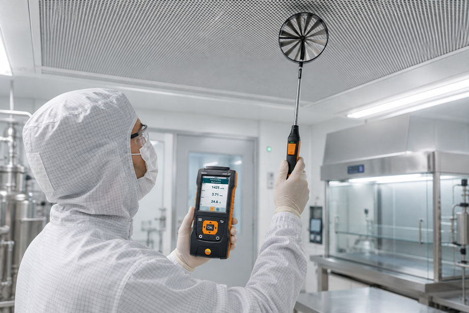
During the qualification of a cleanroom or laminar-flow unit, a single air velocity value is often measured first. If the anemometer indicates, for example, 0.43 m/s, the airflow may initially appear to be satisfactory.
However, such a single-point measurement can be misleading. Immediately next to it, the velocity may be only 0.28 m/s, while another area reaches 0.55 m/s. Possible causes include uneven airflow through the filter, local shielding effects, changes to the HEPA filter, installed equipment or an unsuitable measuring position.
For a reliable test, it is therefore not sufficient to ask only:
“What is the air velocity?”
The following factors are equally important:
- at which plane the measurement is taken,
- how the filter or airflow area is divided into a measurement grid,
- which probe is used,
- how the probe is aligned with the airflow,
- how long measurements are taken at each point,
- how the mean value and local deviations are evaluated.
Especially with unidirectional cleanroom airflow, local minimum values can be considerably more informative than a single overall average.
Suitable measuring instruments and probes can be found at ICS Schneider under air velocity measuring instruments and airflow sensors. Further measuring instruments for humidity and climate parameters can be found under humidity measuring instruments and humidity sensors.
Table of Contents
- What does laminar flow mean in a cleanroom?
- Why “unidirectional airflow” is the more technically accurate term
- What should the airflow test demonstrate?
- Why a single measurement at the filter surface is not sufficient
- Distinguishing between filter outlet, measuring plane and working plane
- What distance from the HEPA filter surface is appropriate?
- How to set up a measurement grid across the filter area correctly
- Positioning measuring points reproducibly
- Thermal or vane probe?
- Why a large vane probe is useful for laminar flow
- When a thermal airflow probe is useful
- Aligning the probe correctly with the airflow
- Calculating the average correctly
- Do not hide local minimum and maximum values in the average
- Determining volumetric flow from velocity and area
- Detecting turbulence and unstable measured values
- Influence of equipment, personnel and work materials
- Temperature and temperature compensation
- Air velocity measurement is not a HEPA filter leak test
- Filter differential pressure as supplementary information
- Performing measurements reproducibly
- What should be included in a test report?
- Typical fault patterns
- Systematic test procedure
- Practical example: local airflow minimum beneath a HEPA filter
- Suitable ICS products for cleanroom and laminar-flow measurements
- Conclusion
- FAQ
What does laminar flow mean in a cleanroom?
The term laminar flow is very commonly used in cleanrooms, safety cabinets, clean-air workstations and production facilities.
In practice, it usually refers to an airflow that is as uniform as possible, with air moving through the clean area in a largely parallel direction.
Typical applications include:
- pharmaceutical filling areas,
- aseptic workstations,
- biotechnology,
- semiconductor manufacturing,
- optical manufacturing,
- laboratory workstations,
- cleanroom ceilings with large-area HEPA or ULPA filters.
The controlled airflow is intended to remove contamination from the critical area in a targeted manner and reduce unwanted transport of particles back toward the product or process.
A high air velocity alone is not sufficient for this.
What is required is an airflow that is:
- sufficient,
- uniform,
- stable in direction
across the relevant area.
Why “unidirectional airflow” is the more technically accurate term
Technical standards frequently use the term unidirectional airflow.
This refers to a controlled airflow whose streamlines within the area being considered run largely parallel and whose velocity is intended to be as uniform as possible.
For cleanroom applications, this term is often more appropriate than the purely fluid-dynamic concept of completely laminar flow.
In a real cleanroom installation, influences are always created by:
- filter frames,
- lighting,
- machine components,
- work surfaces,
- personnel,
- thermal buoyancy,
- moving components.
The practical test therefore focuses on whether the intended airflow performs the required function in terms of velocity, uniformity and direction.
What should the airflow test demonstrate?
Before beginning the measurement, it should be clearly defined what is to be tested.
Possible tasks include:
- determining the velocity directly beneath a HEPA filter surface,
- checking the uniformity of a filter field,
- measuring air velocity at the working plane,
- determining the volumetric flow of a clean-air system,
- detecting changes after a filter replacement,
- searching for local weak airflow zones,
- comparing results before and after maintenance work.
These tasks are not identical.
An air velocity measurement directly beneath the filter, for example, answers the question of how uniformly the air leaves the filter field.
However, it does not automatically indicate how the airflow behaves:
- 50 cm further down,
- at a machine,
- above a product,
- or at the actual working plane.
The measuring plane must therefore already be defined in the test plan.
Why a single measurement at the filter surface is not sufficient
Assume that a HEPA filter field has an area of 1.2 × 0.6 m.
A measurement at the center gives:
v = 0.44 m/s
This value may appear completely plausible.
However, the actual distribution across the filter field could, for example, be:
| Area | Velocity |
|---|---|
| top left | 0.47 m/s |
| center | 0.44 m/s |
| top right | 0.46 m/s |
| bottom left | 0.43 m/s |
| bottom right | 0.27 m/s |
A single measurement at the center would have completely missed the local minimum.
Possible causes of an uneven distribution include:
- uneven airflow approaching the filter,
- changed pressure distribution in the plenum,
- local filter loading,
- shielding by components,
- damage or incorrect installation,
- different filter resistances when several filter elements are used.
The relevant area is therefore divided into a measurement grid.
Distinguishing between filter outlet, measuring plane and working plane
Different measuring positions are often mixed together when discussing cleanroom air velocity.
Filter outlet plane
This is located directly at or very close to the filter surface.
Measurements directly at the filter surface can, however, be influenced by:
- filter geometry,
- protective grilles,
- local outlet structures.
Defined measuring plane below the filter
For a comparable velocity test, a defined plane at a certain distance from the filter surface is therefore often used.
This plane is considered perpendicular to the main airflow direction and is then divided into measuring fields or grid cells.
Working plane
The working plane is located where the actual critical activity takes place.
It may be considerably further away from the filter.
Between the filter surface and the working plane, the airflow can be influenced by:
- machines,
- products,
- tools,
- protective screens,
- personnel.
A measurement at the filter and a measurement at the workplace therefore answer different questions.
What distance from the HEPA filter surface is appropriate?
For assessing supply air velocity with unidirectional airflow, ISO 14644-3 describes a measuring plane approximately 150 to 300 mm from the filter outlet surface or inlet plane.
This distance has an important practical advantage:
The measurement is not taken directly within the small-scale outlet structures of the filter medium, but in a plane where the exiting air can already be assessed more effectively as a coherent velocity field.
Important:
The specific measuring distance must be defined for the respective test and maintained during repeat measurements.
If, for example, the initial qualification was carried out 200 mm beneath the filter surface, a later comparison measurement should not be performed at 50 mm or 500 mm without justification.
Otherwise, differences may arise solely because the measuring plane has changed.
How to set up a measurement grid across the filter area correctly
The measuring plane is divided into individual areas of equal or defined size.
Each grid field is assigned a representative measuring point.
A simple arrangement could, for example, look like this:
| Grid | Point 1 | Point 2 | Point 3 |
|---|---|---|---|
| Row A | A1 | A2 | A3 |
| Row B | B1 | B2 | B3 |
| Row C | C1 | C2 | C3 |
The larger or more complex the filter area, the more measuring points may be required.
The grid should be defined so that:
- the entire relevant area is covered,
- edge regions are not systematically omitted,
- all grid fields can be identified reproducibly,
- the measurement can be repeated during later tests.
Especially when several filter elements are arranged next to each other, it is useful to document the positions of the individual filter boundaries as well.
This makes it possible to determine later whether unusual measured values occur, for example:
- consistently at the same filter,
- at a filter frame,
- or between two filter elements.
Positioning measuring points reproducibly
A grid measurement is only truly meaningful if the sensor is positioned in a comparable manner at every point.
The following should be considered in particular:
- same distance from the filter surface,
- same probe alignment,
- same measuring duration,
- same position within the grid cell,
- as far as possible, the same plant operating conditions.
A typical error occurs when the operator freely moves the probe by hand in front of the filter surface.
Even small changes can result in:
- varying distance,
- tilting of the probe,
- the operator’s hand itself affecting the airflow.
For demanding measurements, a defined holder or otherwise reproducible positioning is therefore advantageous.
Thermal or vane probe?
Different measuring principles are available for low air velocities.
Two particularly common principles are:
- thermal airflow probes,
- vane probes.
Both can be suitable depending on the application, but they have different characteristics.
| Criterion | Thermal probe | Vane probe |
|---|---|---|
| Low air velocities | Very suitable, depending on sensor version | Suitable if the starting velocity is sufficiently low |
| Measuring area | Usually a small sensor head | Larger averaging area depending on diameter |
| Directional dependence | Must be considered depending on design | Vane axis must be aligned with the airflow |
| Local point measurement | Very suitable | Large probe averages over a larger area |
| Laminar-flow grid | Suitable depending on the measurement task | Large high-precision vane probe is very practical |
The selection therefore depends on whether the measurement should be as local as possible or averaged over a somewhat larger area.
Why a large vane probe is useful for laminar flow
Compared with a very small point sensor, a large vane probe has a larger effective measuring area.
As a result, small-scale velocity fluctuations within the probe area are partially averaged.
This can be advantageous with large-area unidirectional airflow.
However, a sufficiently low starting velocity is essential.
A probe that only starts operating reliably at relatively high velocities, for example, would be unsuitable for slower cleanroom airflow.
For the testo 440 offered by ICS, a high-precision vane probe with a Ø 100 mm diameter is available. Its low starting velocity of 0.1 m/s makes it particularly suitable for laminar-flow measurements in cleanrooms.
Depending on the version, the probe can be used either via cable or Bluetooth with the measuring instrument.
When a thermal airflow probe is useful
Thermal anemometers use the cooling effect of the passing air on a heated sensing element.
They are typically very sensitive to low air velocities.
This makes them useful for:
- low airflow velocities,
- local investigations,
- small measuring cross-sections,
- detecting local airflow changes.
However, probe geometry and airflow direction must be taken into account during use.
A small thermal sensor measures much more locally than a 100-mm vane probe.
It can therefore reveal small velocity gradients that a larger probe may already partially average.
This is neither fundamentally better nor worse.
The measurement task and sensor area must match each other.
Aligning the probe correctly with the airflow
A common practical measurement error is caused by incorrect alignment of the airflow probe.
The probe must be positioned relative to the airflow according to its intended measuring direction.
If, for example, a vane probe is held at an angle to the airflow, only part of the actual velocity passes through the measuring plane of the vane.
Under simplified ideal conditions, the effective component can be described approximately as:
veffective ≈ v · cos(α)
where α is the angle between the correct probe alignment and the actual position.
This alone demonstrates:
A reproducible angular position of the probe is part of the measurement.
This effect is particularly critical when two people measure the same filter area while holding the probes at different angles.
Calculating the average correctly
The average airflow velocity can be calculated from the individual grid points.
For equally weighted measuring points:
v̄ = (v1 + v2 + ... + vn) / n
Example with nine measuring points:
| Point | Velocity |
|---|---|
| A1 | 0.43 m/s |
| A2 | 0.45 m/s |
| A3 | 0.44 m/s |
| B1 | 0.46 m/s |
| B2 | 0.44 m/s |
| B3 | 0.45 m/s |
| C1 | 0.42 m/s |
| C2 | 0.44 m/s |
| C3 | 0.31 m/s |
The average may still appear relatively plausible.
Nevertheless, measuring point C3 is significantly lower than the other values.
A test report should therefore not contain only the mean value.
Do not hide local minimum and maximum values in the average
At minimum, the following values are of interest when evaluating a filter field:
- mean value,
- minimum,
- maximum,
- position of the minimum and maximum,
- scatter or uniformity of the individual measured values.
A local relative deviation from the average can, for example, be described as:
Di = (vi − v̄) / v̄ · 100 %
This makes it easy to identify grid areas that deviate significantly from the overall field.
However, it must not be assumed universally which deviation is still permissible.
The acceptance criteria must be derived from the applicable test plan, specification, qualification requirement or relevant standard for the installation.
There is no universal target value that can be applied independently of the application and measuring position to every laminar-flow unit and every cleanroom.
Determining volumetric flow from velocity and area
If a representative mean velocity is available for a defined area, the volumetric flow can generally be determined from it:
Q = v̄ · A
where:
- Q = volumetric flow in m³/s,
- v̄ = mean air velocity in m/s,
- A = flow area in m².
Example:
A filter area is:
A = 1.20 m × 0.60 m = 0.72 m²
The mean velocity is:
v̄ = 0.42 m/s
This gives approximately:
Q = 0.42 m/s × 0.72 m² = 0.3024 m³/s
or:
Q ≈ 1089 m³/h
This calculation assumes that the mean velocity used adequately represents the area through which the air flows.
Detecting turbulence and unstable measured values
An individual measured value may also fluctuate over time.
For example, at the same measuring point the sensor may indicate:
0.35 → 0.44 → 0.39 → 0.47 → 0.36 m/s
In this case, a single spontaneous reading provides little useful information.
Possible causes include:
- actual turbulent airflow,
- fan or control-system fluctuations,
- equipment in the airflow,
- moving personnel,
- unfavorable probe position,
- thermal buoyancy.
For such measurements, time averaging is useful.
The measurement is taken at each grid point over a defined period of time.
Again, reproducibility is important:
If point A1 is averaged over 30 seconds while point A2 is recorded only as a single instantaneous value, the results are only partially comparable.
Influence of equipment, personnel and work materials
Unidirectional airflow can be significantly affected by obstacles.
Typical influences include:
- machine housings,
- filling systems,
- lighting,
- monitors,
- containers,
- tools,
- operators’ arms and hands.
Behind an obstacle, the following may occur:
- vortices,
- flow separation,
- dead zones,
- reverse flow.
The operating condition under which the test was performed must therefore be documented.
Depending on the measurement task, a distinction may be made, for example, between:
- installation without process equipment,
- installation with equipment installed,
- installation under typical operating conditions.
A filter-grid measurement without obstacles and an airflow test in the actual working area provide different information and can complement each other effectively.
Temperature and temperature compensation
The properties of air change with temperature and pressure.
With high-quality airflow probes, these influences are already taken into account to some extent within the instrument design or sensor characteristics, depending on the measuring principle.
Nevertheless, temperature should not be completely ignored during comparative measurements.
Particularly problematic are significant temperature differences caused by:
- newly switched-on systems,
- heat sources beneath the filter,
- hot process equipment,
- cold surfaces,
- direct sunlight.
Temperature gradients can also generate their own air movements and therefore interfere with the intended unidirectional airflow.
Repeat measurements should therefore be performed under thermal operating conditions that are as comparable as possible.
Air velocity measurement is not a HEPA filter leak test
This distinction is particularly important.
A velocity grid can show that one area of a filter field:
- supplies too little air,
- supplies too much air,
- or deviates significantly from neighboring areas.
However, this does not directly demonstrate whether the HEPA filter has a local particle leak.
A filter may, for example:
- have a relatively uniform air velocity,
- while still having a small local leak in the filter medium or seal.
Conversely, a low local velocity does not automatically mean that the filter is leaking.
Possible causes may also include:
- uneven plenum airflow,
- filter resistance,
- shielding,
- fan settings.
A separate HEPA filter leak or integrity test method is therefore required to verify filter integrity.
Air velocity and filter integrity are two different test parameters.
Filter differential pressure as supplementary information
In addition to air velocity, the differential pressure across a filter or filter system can provide important information.
As filter loading increases, flow resistance may also increase.
Depending on the control system of the ventilation installation, this can cause:
- volumetric flow to decrease,
- fan speed to increase,
- differential pressure to increase.
However, differential pressure alone also does not indicate whether a filter has a local leak.
It is instead a supplementary operating parameter.
The testo 440 dP available from ICS, for example, has an integrated differential pressure sensor and can therefore also be used for pressure or filter measurements.
The same principle applies here:
A differential-pressure measurement across a filter is not a substitute for a HEPA integrity test.
Performing measurements reproducibly
For a repeat test after six or twelve months, it is not sufficient to know only which measuring instrument was used.
The measuring method should also be documented in a reproducible manner.
This includes:
- measuring instrument,
- probe type,
- probe serial number,
- calibration status,
- measuring range,
- measuring plane,
- distance from the filter surface,
- grid dimensions,
- number of measuring points,
- measurement duration per point,
- averaging method,
- system operating condition.
Only then can it be determined whether a later change actually originates from the installation or merely from a different measuring method.
What should be included in a test report?
A useful airflow test report should contain more than simply:
“Velocity: 0.42 m/s – OK”.
At minimum, it is useful to include:
- identification of the cleanroom or filter field,
- date and time,
- system operating condition,
- measuring instrument and probe,
- calibration status,
- measuring plane and distance,
- sketch or numbering of the measurement grid,
- individual values for all grid points,
- mean value,
- minimum and maximum,
- defined acceptance limits,
- comments on any abnormalities.
For recurring tests, the grid representation is particularly valuable.
It can, for example, reveal that a specific area decreases over several inspections from:
0.44 → 0.39 → 0.34 m/s
even though the overall mean value remains relatively stable.
Typical fault patterns in laminar-flow and cleanroom measurements
| Observation | Possible cause | Recommended check |
|---|---|---|
| Mean value is plausible, but individual points are significantly lower | Uneven filter field or local airflow disturbance | Display grid values individually and investigate the affected area specifically |
| Measured values are higher at the filter than at the working plane | Airflow expansion, obstacles or lateral deflection | Measure filter plane and working plane separately |
| Measured values differ significantly between two operators | Different probe position or alignment | Standardize holder, distance and alignment |
| Values fluctuate significantly at the same point | Turbulence, fan fluctuations or moving obstacles | Use time averaging and check operating conditions |
| Edge areas show significantly different velocities | Edge or frame effects of the filter field | Document grid positions and filter geometry |
| After filter replacement, one filter field is significantly stronger than neighboring fields | Different pressure drop or filter resistance | Compare velocity grid and, if necessary, differential pressure |
| Measured value drops when the operator stands directly in front of the probe | Person affects the airflow field | Operate the measuring instrument or probe from a distance or using a holder |
| Large vane probe shows a stable value, while a small sensor shows significant local differences | Different spatial averaging characteristics of the two sensors | Compare measurement task and effective sensor area |
| Low air velocity is interpreted as a filter leak | Airflow test confused with filter integrity test | Perform a separate HEPA integrity test |
| Differential pressure is high while air velocity decreases | Increasing filter resistance or system control behavior | Evaluate filter condition, volumetric flow and fan operation together |
| Old and new results do not agree after maintenance | Measuring plane or grid has been changed | Compare test reports and measurement setup |
Systematic test procedure for cleanroom and laminar-flow measurements
A structured test procedure reduces operator influence and makes subsequent repeat measurements easier.
- Define the test objective: Filter outlet, working plane, uniformity or volumetric flow?
- Define the system condition: Document operating condition and relevant installed equipment.
- Define acceptance criteria: Use the requirements from the qualification plan or applicable specification.
- Select measuring instrument: Choose a suitable measuring range and sufficient accuracy for the expected velocity.
- Select probe: Choose a vane or thermal probe appropriate for the measurement task.
- Check calibration status: The measuring instrument or probe must be appropriately calibrated for the test.
- Define measuring plane: Clearly specify the distance from the filter surface.
- Measure filter area: Document width and length.
- Create grid: Define uniform or otherwise specified measuring fields.
- Number measuring points: For example A1, A2, A3, etc.
- Align probe: Position the measuring axis correctly relative to the airflow.
- Allow the first point to stabilize: Do not immediately accept the first displayed value.
- Average the measurement: Use a defined time window or measurement method.
- Measure all grid points: Keep position and procedure unchanged.
- Document individual values: Do not store only the overall average.
- Calculate mean value: Determine the average velocity of the area being evaluated.
- Determine minimum and maximum: Document the corresponding positions as well.
- Evaluate local deviations: Do not conceal unusual areas through averaging.
- Add working-plane measurements if necessary: Check airflow under actual installed equipment.
- Check differential pressure if required: Use as supplementary information for the filter or ventilation system.
- Evaluate filter integrity separately: Do not confuse velocity measurement with leak testing.
- Archive results: Store grid, individual values and measuring conditions for repeat testing.
Practical example: local airflow minimum beneath a HEPA filter
A large filter field in a pharmaceutical clean area is checked regularly.
The filter area is:
1.20 × 1.20 m
The previous routine test consisted of a single measurement approximately at the center.
The measured value there is:
0.43 m/s
At first, there appears to be nothing unusual.
Step 1: Divide the filter area into a grid
For the new test, a defined measuring plane is established beneath the filter surface and divided into several evenly distributed grid areas.
Step 2: Record individual values
All points are measured under comparable conditions using a suitable airflow probe.
Most values are between:
0.40 and 0.46 m/s
However, one grid point shows only:
0.29 m/s
Step 3: Repeat the measurement
The probe is aligned again at the same position.
The lower value is reproducible.
A simple operating or reading error is therefore unlikely.
Step 4: Investigate neighboring points more closely
Additional measuring points are recorded around the unusual area.
This reveals that the velocity is systematically lower across a limited section.
Step 5: Investigate filter and air supply
A HEPA leak is not automatically assumed.
Instead, the following are checked:
- filter element,
- filter frame,
- incoming airflow,
- plenum,
- differential pressure, if applicable.
Step 6: Test filter integrity separately
Because air velocity measurement does not provide evidence of a possible particle leak, the required filter integrity test is carried out as a separate test step.
Step 7: Repeat the measurement
After the cause has been corrected, the same grid is measured again using:
- the same measuring plane,
- the same probe type,
- the same measurement duration.
The velocity distribution is now significantly more uniform.
Result: The original single measurement at the center of the filter had completely missed the local weak area.
The example shows:
For large cleanroom and laminar-flow systems, the spatial distribution of air velocity is at least as important as the overall mean value.
Suitable ICS products for cleanroom and laminar-flow measurements
testo 440 – climate measuring instrument for laminar-flow and cleanroom measurements
The testo 440 is particularly suitable for this application because it can be combined with various digital airflow and climate probes.
For cleanroom and laboratory applications, ICS explicitly lists a high-precision Ø 100 mm vane probe.
Its low starting velocity of 0.1 m/s makes this probe particularly suitable for laminar-flow measurements in cleanrooms.
Depending on the version, it is available:
- with Bluetooth,
- or with a permanently attached cable.
The testo 440 also supports:
- time averaging,
- various airflow probes,
- storage of up to 7,500 measurement reports,
- USB data transfer.
This makes it possible, for example, to record and document a complete velocity grid point by point.
Further information can be found under testo 440 at ICS Schneider.
High-precision Ø 100 mm vane probe – for cleanrooms and laminar flow
The selection of the probe is decisive for the actual air velocity measurement.
The high-precision Ø 100 mm vane probe that can be combined with the testo 440 is specifically designed for low air velocities and is explicitly listed by ICS for laminar-flow measurements in cleanrooms.
The larger probe diameter is particularly practical for large-area unidirectional airflow because it provides averaging across a larger local area.
During use, care should be taken to ensure that:
- the vane is positioned perpendicular to the airflow or in accordance with the specified measuring direction,
- the distance from the filter surface remains constant,
- the operator does not shield the airflow,
- the same averaging time is used at all grid points.
testo 400 – professional climate measuring instrument for extensive cleanroom testing
For more extensive measurement campaigns, the testo 400 universal climate measuring instrument is of particular interest.
ICS explicitly lists applications for:
- laminar-flow measurements in cleanrooms,
- differential-pressure measurements,
- humidity measurements in cleanrooms,
- airflow measurements,
- extensive measurement documentation.
The instrument can be combined with several digital wired and Bluetooth probes.
The integrated documentation function is particularly useful for extensive qualification work.
Measured values, measuring-point information, comments and other data can be managed in a structured manner and then further evaluated and documented using the PC software.
The testo 400 is therefore particularly useful when not only a single filter field is tested, but when the following are regularly documented:
- several cleanrooms,
- several filter fields,
- differential pressures,
- temperature,
- humidity
within a common measurement concept.
Further information can be found under testo 400 at ICS Schneider.
testo 440 dP – airflow and differential pressure with one measuring instrument
If differential pressures are to be checked in addition to air velocity, the testo 440 dP is particularly useful.
The instrument has an integrated differential pressure sensor and, in addition to compatible airflow probes, can therefore be used, for example, for:
- differential-pressure measurements,
- filter pressure measurements,
- checking ventilation systems.
This allows, for example, not only the velocity grid but also the operating condition of a filter system with regard to its pressure loss to be documented.
Important:
Differential-pressure measurement across a filter is not a HEPA filter integrity or leak test.
Further information can be found under testo 440 dP at ICS Schneider.
Which measuring instrument is suitable for the application?
| Measurement task | Suitable solution |
|---|---|
| Measure laminar-flow velocity at a filter field | testo 440 with high-precision Ø 100 mm vane probe |
| Document a velocity grid | testo 440 with suitable airflow probe |
| Extensive cleanroom qualification with several measured variables | testo 400 with suitable digital probes |
| Check airflow plus differential pressure | testo 440 dP with suitable airflow probe |
| Investigate very small local airflow areas | Suitable thermal airflow probe according to measuring range and geometry |
| Check HEPA filter for leakage or integrity | Separate suitable filter integrity test procedure required |
An overview of suitable instruments can be found under air velocity measuring instruments and airflow sensors at ICS Schneider.
Conclusion
When testing laminar-flow or unidirectional cleanroom airflow, a single air velocity value is generally not sufficient.
The decisive factor is the spatial distribution of air velocity across the relevant filter or airflow area.
For a reproducible test, a defined measuring plane should therefore first be established. When measuring unidirectional supply air close to the filter surface, a plane approximately 150 to 300 mm below the filter outlet surface is commonly used.
This plane is then divided into a reproducible grid.
At every grid point, the following must be comparable:
- probe position,
- distance,
- alignment,
- measurement duration.
The mean value alone is then insufficient. The minimum, maximum and positions of local deviations are equally important.
For laminar-flow measurements, a high-precision airflow probe with a sufficiently low measuring range is essential. For the testo 440, for example, a Ø 100 mm vane probe with a starting velocity of 0.1 m/s is available and is specifically intended for cleanroom laminar-flow measurements.
For more extensive qualification work, the testo 400 can additionally provide measuring-point management, extensive documentation and additional climate parameters.
However, distinguishing the airflow test from filter integrity testing is particularly important:
A uniform velocity field does not prove that a HEPA filter is leak-tight – and a local velocity minimum does not prove that it is leaking.
Velocity distribution, differential pressure and filter integrity are different test parameters and should therefore be evaluated separately.
For practical applications, the following procedure applies:
Define test objective → define measuring plane → create grid → select suitable probe → measure all points reproducibly → document individual values → evaluate mean value and local deviations → add working-plane measurements if required → test filter integrity separately → document measurement setup for repeat testing.
FAQ: Measuring laminar flow and air velocity in cleanrooms
How do you measure air velocity in laminar flow?
The relevant airflow area is divided into a defined measurement grid. At each grid point, air velocity is measured with a suitable probe under conditions that are as identical as possible. The individual values, mean value, minimum and maximum are then evaluated.
What is the difference between laminar flow and unidirectional airflow?
In cleanroom applications, the term laminar flow is often used colloquially. Technically, the term unidirectional airflow is generally used, meaning a controlled airflow with largely parallel airflow direction and a defined velocity distribution.
How far should the airflow probe be from the HEPA filter?
For testing unidirectional supply air close to the filter outlet surface, ISO 14644-3 describes a measuring plane approximately 150 to 300 mm away from the filter surface or inlet plane. However, the specific test method must correspond to the applicable test plan.
Can I measure directly at the HEPA filter surface?
Measurements directly at the filter surface can be influenced by the filter medium, protective grille and local outlet structures. For reproducible velocity testing, a defined measuring plane at a distance from the filter is therefore often used.
Why is a measurement grid required?
A single measuring point can miss local areas with excessively high or low velocity. A grid shows the spatial velocity distribution across the entire relevant area.
How large should the measurement grid be?
The grid division depends on the filter area, installation geometry, test requirements and applicable test method. It is important that the area is covered representatively and reproducibly.
Where is the measurement taken within a grid cell?
For a defined grid measurement, a reproducible point within each grid cell is typically used. It is essential that the same arrangement be maintained across the entire area and during subsequent repeat measurements.
Does every grid cell have to be the same size?
For systematic velocity testing of a uniformly assessed area, equally sized or otherwise clearly defined grid areas are useful. Different geometries should be taken into account and documented in the test plan.
Which probe is suitable for laminar-flow measurements?
Airflow probes whose measuring range and accuracy are suitable for the expected low air velocity should be used. For the testo 440, ICS offers a high-precision Ø 100 mm vane probe that is specifically intended for laminar-flow measurements in cleanrooms.
What is the starting velocity of the high-precision testo vane probe?
The high-precision Ø 100 mm vane probe that can be used with the testo 440 has a specified starting velocity of 0.1 m/s.
Why is a large vane probe useful?
The larger effective measuring area partially averages small-scale velocity differences and is therefore very practical for large-area unidirectional airflow.
When should a thermal airflow probe be used?
Thermal probes are particularly useful at very low air velocities and when a more local measurement with a small sensor head is required.
Is a thermal probe more accurate than a vane probe?
Not necessarily. Accuracy, measuring range, sensor geometry and application must be considered together. A small thermal probe and a large vane probe also measure spatially different areas.
How important is the alignment of the airflow probe?
Very important. If a direction-sensitive probe is tilted relative to the airflow, the indicated velocity may be lower. Probe alignment should therefore be reproducible at all measuring points.
Should an instantaneous value or an average be used?
For fluctuating airflow, time averaging is generally more meaningful. It is important that the same measuring and averaging method be used at all grid points.
How is the mean air velocity calculated?
For equally weighted measuring points, all individual velocity values are added together and divided by the number of measuring points.
Is the mean value alone sufficient for evaluation?
No. A good mean value can hide individual areas that are significantly too low or too high. Minimum, maximum and spatial distribution should therefore also be considered.
How is volumetric flow calculated from air velocity?
With a representative mean velocity, the approximation Q = v̄ × A can be used. A is the area through which the air flows.
Is there a target value of 0.45 m/s for every cleanroom?
No. A specific velocity value must not be applied universally to every cleanroom application. Target and acceptance values result from the system concept, application, qualification requirements and relevant standards.
Why do measured values differ between the filter and the working plane?
Between the filter and the working plane, the airflow cross-section can change and obstacles, machines, products or thermal effects can influence the airflow.
Can an operator influence the measurement?
Yes. The operator’s body, hands and arms can significantly influence low cleanroom airflow. The operator should therefore remain outside the relevant airflow as far as possible and position the probe reproducibly.
How can turbulence be identified?
Strongly fluctuating velocity values at a constant measuring point may indicate turbulence or unstable airflow. A time-based measurement series is more informative than a single instantaneous reading.
Can a machine beneath the HEPA filter change the airflow?
Yes. Installed equipment can divide or deflect airflow and create vortices or dead zones. A test at the actual working plane can therefore be useful in addition to testing at the filter plane.
Can an HEPA filter leak be detected by measuring air velocity?
A velocity grid can indicate an unusual airflow area, but it does not prove the presence of a particle leak. A separate suitable test procedure is required for filter integrity.
Does low air velocity automatically mean that the HEPA filter is damaged?
No. Possible causes include uneven incoming airflow, high filter resistance, plenum problems or airflow shielding.
Can a HEPA filter leak even if the air velocity is uniform?
Yes. A local leak in the filter medium or seal does not necessarily cause a clearly visible change in air velocity.
What does differential pressure indicate about a HEPA filter?
Differential pressure provides information about the flow resistance of the filter or filter system. It is useful for operational monitoring but does not directly prove filter integrity.
Which ICS instrument can measure both airflow and differential pressure?
The testo 440 dP has an integrated differential pressure sensor and can be combined with suitable airflow probes.
Which measuring instrument is suitable for extensive cleanroom qualification?
The testo 400 is particularly suitable for extensive climate and cleanroom measurements. It can be combined with various digital probes and provides extensive options for managing and documenting measured values.
Can the testo 400 be used for laminar-flow measurements?
Yes. ICS explicitly lists laminar-flow measurements in cleanrooms as an application for the testo 400.
Why is the calibration status of the airflow probe important?
The probe is the actual measuring transducer. For quality-relevant measurements, it should therefore be ensured that the probe being used is operating within the intended calibration status.
What should be included in the measurement report?
At minimum, the measuring instrument, probe, calibration status, filter area, measuring plane, distance, grid, individual values, mean value, minimum, maximum, system operating condition and acceptance criteria should be documented.
Why should the measurement grid remain unchanged for repeat testing?
Changes over time can only be evaluated meaningfully if the measuring plane, positioning and grid arrangement are comparable.
What should be checked after replacing a HEPA filter?
Depending on the system and qualification concept, the velocity distribution, volumetric flow, differential pressure and filter integrity may need to be checked again. These test parameters should be documented separately.
Where can I find suitable airflow measuring instruments at ICS Schneider?
An overview can be found under air velocity measuring instruments and airflow sensors at ICS Schneider.