


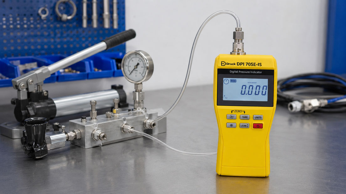
During pressure calibration, the reference instrument and the device under test must be exposed to the same stable test pressure at the same time. If the pressure falls during the reading or continues to rise after adjustment, measurement deviation, repeatability and hysteresis can hardly be assessed reliably.
However, the cause is not always a leaking connection. Particularly during pneumatic testing, heating caused by pressure generation, subsequent cooling, large hose volumes and elastic deformation can produce an apparent pressure loss. In hydraulic systems, trapped air, hose expansion and the settling of seals play an important role.
A reliable leak-rate measurement therefore requires a defined test setup, sufficient stabilisation time and a clear distinction between the pressure-change rate and the actual escaping volumetric or mass flow.
Table of Contents
- Distinguishing pressure drop from leak rate
- Why a test pressure does not remain stable
- Temperature equalisation during pneumatic testing
- Influence of hose and test volume
- Comparing pneumatic and hydraulic systems
- Designing a low-leakage test setup
- Carrying out a leak test systematically
- Defining stabilisation and test time
- Locating a leak in the test setup
- Reference instrument and pressure stability
- Evaluating limits and results
- Documenting the leak test traceably
- Typical errors during rapid calibrations
- Practical example: Pneumatic calibration up to 10 bar
- Selecting the correct test equipment
- Which products are suitable?
- Conclusion
- Frequently asked questions
Distinguishing pressure drop from leak rate
During a simple leak test, a test volume is pressurised to a specified value, isolated from the pressure source and observed over a defined period.
The pressure-change rate can be calculated as follows:
Pressure-change rate = (final pressure − initial pressure) / test time
Example:
- Initial pressure: 10.000 bar,
- Final pressure after five minutes: 9.975 bar,
- Pressure change: −0.025 bar,
- Pressure-change rate: −0.005 bar/min or −5 mbar/min.
This value initially describes only how quickly the pressure changes within the specific test setup. It is not yet a universally comparable volumetric leak rate.
For an enclosed gas volume, assuming constant temperature and constant volume, a change in the amount of substance can be derived from the pressure change:
|dn/dt| = V / (R × T) × |dp/dt|
At least the following must be known:
- total enclosed test volume,
- absolute temperature of the gas,
- absolute pressure change,
- test duration,
- the required reference conditions where applicable.
A value stated in mbar/min is therefore useful for repeated tests using the same setup. If different test benches are to be compared or actual gas losses are to be stated, the leak rate must, for example, be determined in mol/s, sccm or as a defined standard volumetric flow rate.
Why a test pressure does not remain stable
A falling or rising pressure can have several causes:
| Observation | Possible cause |
|---|---|
| Pressure falls sharply immediately | Open vent valve, loose connection, damaged seal or incompletely closed valve |
| Pressure initially falls quickly and then more slowly | Cooling of the previously compressed gas, material settling or a combination of temperature equalisation and a small leak |
| Pressure rises after isolation | Heating of the enclosed medium, regulator creep or medium flowing through a valve |
| Pressure fluctuates periodically | Ambient-temperature changes, unstable pressure source, mechanical movement or a pulsating system |
| Hydraulic pressure falls despite dry connections | Trapped air, hose expansion, deformation of the device under test or settling of seals |
| Drift occurs only at high pressure | Pressure-dependent leakage, increasing elastic deformation or an unsuitable connection |
Before calibration, it must therefore be clarified whether medium is actually escaping or whether the pressure is changing due to thermal and mechanical equalisation effects.
Temperature equalisation during pneumatic testing
When gas is compressed quickly, its temperature rises. After isolation, the gas transfers heat to the hoses, adapters and surroundings. The temperature falls and so does the pressure, even in a completely leak-tight system.
Conversely, a cold test setup may show an increasing pressure after being moved into a warmer environment.
The effect is particularly pronounced with:
- rapid pumping,
- large pressure changes,
- large enclosed gas volumes,
- long plastic hoses,
- low pressure ranges with high resolution,
- changing ambient conditions.
A stabilisation phase should therefore be allowed after approaching the test point. During this period, the pressure may be readjusted. Only afterwards is the source isolated and the actual leak-test period started.
For demanding tests, it is advisable to record the pressure and ambient temperature or the temperature of the test system simultaneously. A steady pressure drop occurring in parallel with a falling temperature does not automatically indicate a leak.
Influence of hose and test volume
The enclosed volume influences how strongly a specific quantity of escaping gas appears as a pressure drop.
For the same physical leak:
- small volume: faster and more clearly visible pressure drop,
- large volume: slower pressure drop, but a greater total quantity of gas escapes for the same pressure change.
Two test benches can therefore indicate different values in mbar/min despite having the same leak.
For reproducible results, the test volume should remain as constant as possible. It includes:
- the reference sensor,
- the device under test,
- manifolds and valves,
- hoses and adapters,
- internal volumes of the hand pump or pressure regulator if they are not isolated.
Short hoses and small dead volumes also improve controllability and reduce stabilisation time.
Comparing pneumatic and hydraulic systems
| Criterion | Pneumatic testing | Hydraulic testing |
|---|---|---|
| Test medium | Air or inert gas | Water or suitable oil |
| Compressibility | High | Low |
| Temperature influence | Very significant | Usually lower but not negligible |
| Leak detection | Small leaks can be detected effectively through pressure decay | Very small quantities of liquid can already cause significant pressure changes |
| Typical disturbance | Thermal pressure decay and large gas volume | Trapped air and elastic volume changes |
| Safety consideration | High stored energy in the compressed gas | Less expansion energy but possible liquid discharge |
Hydraulic systems often appear more stable when they have been completely vented. However, even a small trapped air bubble can act like a spring and considerably impair pressure adjustment and stability.
During hydraulic testing, the lines and device under test should therefore be filled and vented carefully. The system can then be preloaded several times so that hoses, seals and mechanical components can settle.
Designing a low-leakage test setup
A typical comparison setup consists of:
Pressure source → fine regulator → isolation valve → manifold → reference instrument and device under test
The following points are important for a stable setup:
- hoses that are as short and pressure-resistant as possible,
- few adapters and transitions,
- clean, undamaged sealing surfaces,
- a sealing method suitable for the thread,
- O-rings and seals suitable for the medium and pressure,
- separate isolation and vent valves,
- installation without mechanical stress,
- sufficient distance from heat sources.
Parallel G threads are normally sealed using a defined sealing face or sealing ring. Tapered threads such as NPT seal through the thread. An unsuitable combination of thread, adapter and sealing material can cause both leakage and damaged connections.
Hoses must not be twisted or installed under tensile stress. Hose movement can change the enclosed volume and therefore influence the pressure.
Carrying out a leak test systematically
- Check the test setup: Verify the connections, seals, pressure limits and medium.
- Condition the system: Apply the intended pressure at least once and then release it again.
- Generate the test pressure: Approach the target value slowly without excessive overshoot.
- Allow the system to stabilise: Wait for thermal and material equalisation and readjust if necessary.
- Isolate the pressure source: Close the isolation valve without generating an additional pressure impulse.
- Record the initial value: Document the initial pressure only after the specified stabilisation period.
- Wait for the test period: Record pressure and, where possible, temperature continuously.
- Record the final value: Calculate the pressure change and pressure-change rate.
- Evaluate the result: Compare it with the specified limit and ambient conditions.
- Depressurise safely: Completely release the system pressure before loosening any connections.
A leak test should be repeated under the same conditions wherever possible. Only then can results be compared over longer periods.
Defining stabilisation and test time
There is no universal stabilisation or test time for all pressure ranges and test volumes. The duration must match the dynamics of the setup.
| Test situation | Typical behaviour | Suitable approach |
|---|---|---|
| Small hydraulic volume | Rapid stabilisation and very high sensitivity to small volume changes | Vent carefully and verify a short holding period after preloading |
| Pneumatic test with a short hose | Moderate temperature equalisation | Use a defined stabilisation period before measurement |
| Large device under test or long hose | Slow thermal equalisation | Allow longer stabilisation and test times |
| Very low pressure range | The smallest temperature and volume changes are visible | Use a thermally stable environment and sensitive pressure control |
| High hydraulic pressure | Settling and elastic deformation | Preload several times before evaluation |
A short test duration reveals large leaks quickly but may be insufficiently sensitive to small leak rates. A very long test duration increases sensitivity but also makes the result more susceptible to temperature changes.
The selected stabilisation and test times should therefore form part of the work instruction and should not be changed spontaneously for each measurement.
Locating a leak in the test setup
If the complete setup shows an impermissible pressure change, the source should be isolated systematically:
- Check the pressure source: Seal the outlet of the pump or regulator using a suitable blanking plug.
- Check the reference branch: Pressurise only the reference instrument, manifold and short connecting line.
- Add the device-under-test branch: Connect the hose and adapter for the device under test, but initially replace or isolate the device itself.
- Connect the device under test: Test the actual measuring instrument only after the test setup itself has proven stable.
- Compare pressure levels: Repeat the test at low, medium and high pressure.
This makes it possible to determine whether the leak originates from the pump, vent valve, manifold, reference instrument, hose, adapter or device under test.
A valve may appear satisfactory when open but leak across its seat only when isolated. A pressure regulator may also continue to supply medium slowly and partly conceal an actual leak.
Reference instrument and pressure stability
The reference instrument must be sufficiently accurate, but it must also provide suitable resolution, repeatability and short-term stability.
A fluctuating indication may be caused by:
- actual pressure changes,
- excessive display resolution with unstable pressure,
- temperature drift of the reference sensor,
- electrical filtering or sampling functions,
- mechanical pulsations from the pressure source.
An averaging or filter function can make the reading steadier. However, it must not be used to conceal a real pressure drop.
The reference instrument and device under test should be connected to the same manifold and positioned at the same height wherever possible. In hydraulic systems, a height difference can cause an additional hydrostatic pressure difference.
Evaluating limits and results
A general limit such as “maximum 1 mbar/min” cannot be applied universally without further information. The permissible pressure change depends on:
- test pressure,
- test volume,
- medium,
- test duration,
- temperature stability,
- tolerance of the device under test,
- required measurement uncertainty,
- the company’s work instruction.
For calibration, the decisive point is that the pressure change during the actual reading period must be sufficiently small. It should be considerably lower than the measurement uncertainty or permissible deviation of the device under test.
Example: If a pressure gauge with a tolerance of ±0.10 bar is to be evaluated, a pressure drop of 0.05 bar during the reading would already be critical. During a high-accuracy reference test, even a change of only a few millibar may be unacceptable.
Documenting the leak test traceably
A leak-test report should include at least:
- identification of the reference instrument and device under test,
- test medium,
- test pressure and pressure reference,
- test setup and hoses or adapters used,
- stabilisation time,
- test duration,
- initial and final pressure,
- calculated pressure-change rate,
- ambient or system temperature,
- permissible limit,
- pass or fail assessment,
- date and person carrying out the test.
If an actual volumetric or molar leak rate is stated, the test volume, reference pressure, reference temperature and calculation method used must also be documented.
Typical errors during rapid calibrations
The measured value is read immediately after pumping
The compressed gas is still cooling. The resulting pressure drop is incorrectly interpreted as a leak or measurement deviation.
Stabilisation time and test time are mixed
The complete thermal equalisation period is included in the calculated leak rate.
The pressure source remains connected
The pump or regulator may continue supplying pressure and conceal an existing leak.
Different hose lengths are compared
The pressure-change rates are not directly comparable because the test volumes differ.
A hydraulic setup is not vented
Trapped air causes unstable fine adjustment and prolonged settling behaviour.
Only the device under test is suspected
The actual leak is located at the manifold, valve, reference instrument or adapter.
The test pressure is significantly exceeded
Subsequent downward adjustment changes the pressure direction and temperature state and may distort the calibration sequence.
The leak test is performed differently at every test point
The results cannot be compared with one another or with previous tests.
Practical example: Pneumatic calibration up to 10 bar
A pressure transmitter with a range from 0 to 10 bar is to be tested using a pneumatic hand pump and a digital reference instrument. After setting 10 bar, the pressure falls to 9.94 bar within two minutes.
A leak is initially suspected. However, examination of the test procedure shows:
- The pressure was generated using rapid pump strokes.
- The measurement began immediately after the valve was closed.
- The connecting hose is two metres long.
- The ambient temperature remains constant.
The test is repeated. After reaching 10 bar, the system is allowed to stabilise for five minutes and is readjusted several times. Only then is the pressure source isolated.
The pressure now falls from only 10.000 to 9.990 bar within five minutes. The pressure-change rate is:
−0.010 bar / 5 min = −0.002 bar/min
For an additional check, the device under test is replaced with a blanking plug. The pressure drop remains almost identical. The cause is therefore located in the test setup rather than in the transmitter.
After replacing a damaged flat seal and shortening the hose, the pressure change following stabilisation is less than 1 mbar within five minutes.
Only then is the actual calibration carried out using increasing and decreasing test points.
Selecting the correct test equipment
At least the following information is required when selecting a suitable calibration and leak-test system:
- pneumatic or hydraulic testing,
- vacuum and minimum and maximum test pressure,
- required pressure resolution and accuracy,
- size of the device under test and expected test volume,
- required pressure-change or leak-rate resolution,
- manual or automatic pressure generation,
- required stabilisation and fine adjustment,
- test duration and number of test points,
- mobile or stationary application,
- temperature measurement and data logging,
- process connections, hoses and adapters,
- calibration and documentation requirements.
For very low pressure ranges, a small dead volume, sensitive valves and thermal stability are particularly important. At high hydraulic pressures, complete venting, media-compatible components and safe depressurisation are the main priorities.
Which products are suitable?
Pressure calibration equipment
The pressure calibration equipment category includes calibration pumps, pressure regulators, reference instruments, portable calibrators, automatic pressure controllers, deadweight testers, hoses and adapters.
These products can be used to create both manual on-site test arrangements and automated calibration and leak-test procedures.
Manual pressure regulators
The manual pressure regulators category includes fine-pressure regulators, volume adjusters, manifolds and other components for controlled test-pressure generation and stabilisation.
A manual regulator particularly influences:
- sensitivity of pressure adjustment,
- overshoot behaviour,
- stabilisation time,
- controlled isolation and venting,
- repeatability of the test points.
Measurement accuracy continues to be determined by the reference instrument. The regulator ensures that the reference pressure can be adjusted with sufficient stability.
Druck DPI705E precision pressure indicator
The Druck DPI705E is a portable precision instrument for maintenance, troubleshooting and pressure calibration.
Functions relevant to this application include:
- integrated leak test,
- minimum/maximum indication,
- filter and tare functions,
- internal and external pressure sensors,
- different pressure ranges up to 1,400 bar,
- optional intrinsically safe version.
The leak-test function can record the pressure change over a defined period. When evaluating the result, it must still be considered whether the pressure loss is caused by a leak or by temperature and volume effects.
Druck DPI610E portable pressure calibrator
The Druck DPI610E combines pressure generation, reference measurement and calibration functions in one portable instrument.
Among other features, it offers:
- integrated leak test,
- pneumatic pressure generation and vacuum,
- volume adjuster for fine pressure control,
- controlled venting for decreasing test points,
- recording of pressure decay and leak rate,
- optional temperature measurement using an RTD sensor.
The additional temperature recording helps distinguish actual leakage from thermally induced pressure drift.
Druck PV411A four-in-one hand pump
The Druck PV411A can generate pneumatic pressure up to 40 bar, hydraulic pressure up to 700 bar and vacuum down to approximately −960 mbar.
The integrated volume adjuster enables fine adjustment of the test pressure. During hydraulic operation, a vacuum priming function assists in removing trapped air that could otherwise impair pressure stability.
The PV411A is particularly suitable for mobile testing involving changing pneumatic and hydraulic tasks.
Conclusion: Stable test pressure is achieved only after controlled stabilisation
A pressure drop during calibration is a warning signal, but it is not unambiguous proof of a leak. Particularly with gases, temperature equalisation and test volume can significantly influence the pressure.
A leak-rate measurement must clearly separate the stabilisation period from the actual test period. Only after thermal and mechanical equalisation is the pressure source isolated and the pressure change recorded over a defined period.
Values in mbar/min or bar/min always apply to the specific test setup. To calculate an actual volumetric or molar leak rate, the volume, temperature, absolute pressure values and reference conditions must also be known.
Short hoses, few adapters, clean sealing surfaces and complete venting improve stability. Step-by-step isolation or the use of a blanking plug makes it possible to determine whether the leak is located in the test bench or in the device under test.
The calibration results are reliable and reproducible only when the pressure remains sufficiently stable during the reading period.
Frequently asked questions about leak-rate measurement during pressure calibration
Why does the pressure fall immediately after pumping?
During pneumatic testing, the gas heats up as it is compressed. When it subsequently cools, the pressure falls even without a leak. Hoses and seals may also settle.
Is a pressure drop in mbar/min an actual leak rate?
Initially, it is the pressure-change rate of the specific test setup. To calculate a volumetric or molar leak rate, the test volume, absolute temperature and reference conditions must also be considered.
How long must the test pressure be allowed to stabilise?
This depends on the medium, pressure change, hose volume, device under test and accuracy requirement. The stabilisation time should be established experimentally and then specified as mandatory in the work instruction.
Why is a hydraulic test pressure unstable?
Air bubbles are frequently present in the system. Other causes include hose expansion, elastic deformation of the device under test, temperature changes or a leaking valve or seal.
How can I determine whether the device under test is leaking?
The test setup is first tested using a blanking plug. The hose, adapter and device under test are then added step by step. This makes it possible to identify the faulty section.
Should the pressure pump remain connected during the leak test?
The test section should be isolated from the pressure source using a suitable valve. Otherwise, the pump may continue supplying pressure or lose pressure itself and distort the result.
Why does the hose length influence the result?
A longer hose increases the enclosed volume and can expand elastically under pressure. This affects both the pressure-change rate and the stabilisation behaviour.
Which leak-rate limit is permissible?
There is no universal limit. It must be derived from the test volume, test pressure, test duration, medium, temperature conditions and required calibration accuracy.
Which information does ICS Schneider require for selection?
The required information includes the pressure range, test medium, pneumatic or hydraulic application, required accuracy, expected test volume, required leak-test resolution, test duration, mobile or stationary design, and requirements for temperature recording and documentation.