


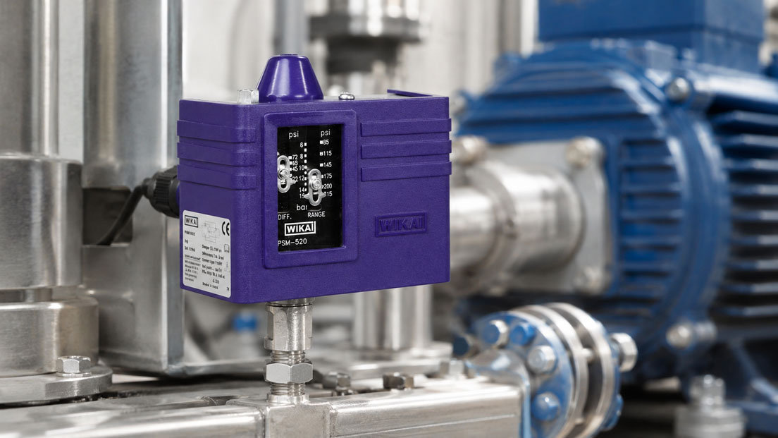
When a customer requests a pressure switch, the required switching point is often the only information initially provided. However, this is not sufficient for reliable selection. A mechanical pressure switch operates with a moving pressure element and an electrical contact. An electronic pressure switch measures the pressure using a sensor cell and processes the signal electronically.
Both versions can monitor pumps, compressors, hydraulic systems or process plants. However, they differ significantly in terms of display, configuration, switching frequency, diagnostics, power supply, electrical connection and cost.
The electronic version is not automatically better, and the mechanical solution is not fundamentally outdated. The decisive factor is the actual function that the pressure switch is intended to perform within the system.
Table of Contents
- What is the purpose of a pressure switch?
- How does a mechanical pressure switch work?
- How does an electronic pressure switch work?
- Comparison of mechanical and electronic pressure switches
- Switching point, reset point and hysteresis
- Distinguishing mechanical contacts, PNP, NPN and relays
- Supply voltage and behaviour during a power failure
- Assessing accuracy and repeatability
- Switching frequency and service life
- Pressure peaks, pulsation and overload
- Vibration, shock and installation conditions
- Display and configuration
- Diagnostics and troubleshooting
- IO-Link and PLC connection
- Combining a switching output and analogue signal
- Medium, materials and process connection
- Temperature, degree of protection and hazardous areas
- Limitations for safety functions
- Purchase costs and total expenditure
- Typical applications for both device types
- Decision guide for device selection
- Typical selection errors
- Practical example: Pressure monitoring on a hydraulic power unit
- Which products are suitable?
- Conclusion
- Frequently asked questions
What is the purpose of a pressure switch?
A pressure switch monitors a defined pressure value and changes the state of an electrical output when this value is reached.
Typical functions include:
- switching on a pump when the pressure is too low,
- stopping a compressor when the cut-off pressure is reached,
- releasing a machine only when sufficient clamping pressure is available,
- triggering an alarm in the event of pressure loss,
- monitoring the maximum pressure,
- detecting filter contamination using differential pressure,
- controlling a valve or coupling relay,
- transmitting the pressure status to a PLC.
The pressure switch does not necessarily measure a continuous pressure value for a control system. Its primary function is initially limit monitoring.
If the complete pressure profile must also be transmitted, stored or visualised, either an electronic pressure switch with an analogue output or digital interface, or a separate pressure transmitter, is required.
How does a mechanical pressure switch work?
In a mechanical pressure switch, the process pressure acts on a moving measuring element. Depending on the pressure range and design, this may be:
- a diaphragm,
- a piston,
- a bellows,
- a Bourdon tube.
The movement of the measuring element is transferred against a spring force. As soon as the set pressure is reached, the mechanism actuates a microswitch or another electrical contact.
Depending on the version, the switching point is changed using an adjusting screw, spring or adjustment mechanism inside the housing.
Typical characteristics of mechanical pressure switches include:
- no auxiliary power required for pressure measurement,
- direct electrical contact,
- frequently a potential-free normally closed, normally open or changeover contact,
- robust and straightforward design,
- mechanically defined or adjustable switching differential,
- usually no digital pressure display,
- no digital configuration or diagnostics.
The mechanical design is particularly suitable when a simple limit function is required independently of electronic signal processing.
How does an electronic pressure switch work?
An electronic pressure switch contains a pressure sensor cell. This first converts the applied pressure into an electrical sensor signal. The internal electronics process the signal and compare the measured value with the configured switching limits.
Depending on the device, ceramic, piezoresistive or metallic thin-film sensor cells may be used for pressure measurement.
The result is provided through one or more electronic outputs. Typical functions include:
- PNP or NPN switching output,
- one or two freely configurable switching points,
- adjustable hysteresis,
- window function,
- switching delay,
- digital display,
- Min./Max. memory,
- analogue output,
- IO-Link or another digital interface.
Electronic pressure switches require a supply voltage. They are frequently connected directly to a digital PLC input.
Comparison of mechanical and electronic pressure switches
| Criterion | Mechanical pressure switch | Electronic pressure switch |
|---|---|---|
| Measuring principle | A diaphragm, piston, bellows or Bourdon tube actuates a contact | Electronic pressure sensor cell with signal processing |
| Auxiliary power | Not required for pressure measurement | Required |
| Output | Usually mechanical normally closed, normally open or changeover contact | Usually PNP, NPN, push-pull, analogue signal or IO-Link |
| Display | Usually none | Integrated digital display depending on the version |
| Configuration | Mechanical adjustment on the device | Via buttons, display, software or IO-Link |
| Hysteresis | Fixed, mechanically determined or adjustable within limits | Usually freely adjustable within permissible limits |
| Multiple switching points | Only with a suitable contact or device version | Frequently two independently configurable outputs |
| Diagnostics | Limited to contact and pressure testing | Status, fault and process information depending on the device |
| Switching frequency | Contact wear must be considered | Electronic outputs suitable for frequent switching |
| Integration | Simple electrical circuit or relay logic | PLC, control system, IO-Link and automated configuration |
| Typical advantage | Simple, robust limit monitoring | Flexible adjustment, display and automation integration |
Switching point, reset point and hysteresis
Regardless of the device type, the switching point and reset point must be distinguished.
Example of maximum-pressure monitoring:
- switching point with increasing pressure: 8 bar,
- reset point with decreasing pressure: 7 bar,
- hysteresis or switching differential: 1 bar.
Hysteresis prevents the output from constantly switching on and off in response to small pressure fluctuations.
In mechanical pressure switches, the switching differential is produced by the mechanics of the measuring element, spring and microswitch. Depending on the version, it may be fixed, dependent on the configured switching point or adjustable within a defined range.
In electronic pressure switches, the switching and reset points can frequently be configured separately. This allows the hysteresis to be adapted specifically to the system.
Very small hysteresis enables narrow pressure control but may result in frequent switching in pulsating systems. Large hysteresis reduces the switching frequency but increases the pressure range between switching on and off.
Distinguishing mechanical contacts, PNP, NPN and relays
Mechanical contact
Mechanical pressure switches frequently contain a microswitch with a normally closed, normally open or changeover function. Depending on the version, the contact may be potential-free.
The permissible switching capacity must be suitable for the connected load. The following must be checked:
- switching voltage,
- switching current,
- AC or DC voltage,
- resistive or inductive load,
- inrush current,
- switching frequency.
A high contact current printed on the device frequently applies only to a resistive load. Solenoid valves, contactors and relays generate voltage peaks when switched off and may require protective circuitry or a coupling relay.
PNP output
A PNP output switches the positive supply voltage to the PLC input. This output type is widely used in European machine-control systems.
NPN output
An NPN output switches the current towards 0 V. The controller, reference potential and input circuit must be suitable for this arrangement.
Relay output
Some electronic pressure switches have a relay output. This can provide potential-free isolation but, like any mechanical contact, has a limited switching service life.
The terms PNP, NPN and relay describe the electrical output type. Normally closed, normally open and window function, by contrast, describe the required switching logic.
Supply voltage and behaviour during a power failure
A mechanical pressure switch does not require auxiliary power for mechanical pressure measurement. Its contact is actuated directly by the pressure mechanism.
However, the connected signalling or load circuit still requires an electrical power supply.
An electronic pressure switch, by contrast, requires a defined operating voltage, frequently from the machine’s 24 V DC network. Without this supply, neither the measured value nor the switching output is available.
During planning, it must therefore be defined how the controller recognises the following conditions:
- normal process pressure,
- pressure limit reached,
- pressure-switch supply failure,
- cable interruption,
- sensor fault,
- short circuit at the output.
Normally closed logic can make it easier to detect certain cable interruptions. However, it does not replace a complete assessment of the wiring and fault behaviour.
Assessing accuracy and repeatability
For pressure switches, the general measuring accuracy is not the only relevant factor. What matters is how accurately and repeatedly the actual switching point is reached.
The following must be distinguished:
- switching-point accuracy,
- repeatability,
- hysteresis,
- temperature influence,
- long-term drift,
- adjustment resolution,
- response time.
Mechanical pressure switches are sufficiently accurate for many operational monitoring tasks. However, their switching point can be influenced more strongly by the spring, mechanics, temperature and wear.
Depending on the device, electronic pressure switches frequently enable finer adjustment and better reproducibility. Nevertheless, the actual values must be checked against the respective data sheet.
An easily readable digital display does not prove that the switching accuracy is correspondingly high. Display resolution, measurement deviation and switching-point tolerance are different specifications.
Switching frequency and service life
Each mechanical switching operation places stress on the contacts and actuating mechanism. The electrical service life depends heavily on the connected load.
Particularly demanding conditions include:
- high switching currents,
- inductive loads,
- frequent switching cycles,
- contact bounce,
- inadequate spark suppression,
- strong vibration.
Electronic transistor outputs do not contain mechanically wearing switching contacts. They are therefore frequently advantageous for short machine cycles and high switching frequencies.
However, an electronic pressure switch is not infinitely loadable either. The maximum output current, short-circuit behaviour, ambient temperature and electrical protective measures must be observed.
If a pump or compressor switches unusually frequently, the pressure switch should not be the only component assessed. Possible causes also include:
- hysteresis that is too small,
- pressure accumulator that is too small,
- incorrect accumulator pre-charge pressure,
- leakage,
- strong pressure pulsation,
- unsuitable switching point.
Pressure peaks, pulsation and overload
The normal operating pressure is not necessarily the highest pressure applied to the pressure switch. Pumps, valves, rapid closing operations and hydraulic cylinders can generate short pressure peaks.
These peaks can:
- mechanically overload the measuring element,
- briefly exceed the switching point,
- trigger incorrect switching operations,
- reduce long-term stability,
- damage the diaphragm or sensor cell.
At least three pressure values are therefore required for selection:
- normal operating pressure,
- required switching point,
- maximum possible pressure, including peaks.
Depending on the system, a pressure snubber, restrictor, measuring line or damped connection point may be appropriate. However, any damping also slows the pressure switch’s response.
Vibration, shock and installation conditions
Pressure switches are frequently mounted directly on pumps, compressors or hydraulic power units. In addition to the pressure, they are therefore exposed to vibration, mechanical shock and temperature fluctuations.
Strong vibrations can cause the following problems in mechanical pressure switches:
- contact chatter,
- shifting of the switching point,
- fatigue of mechanical components,
- loosening of electrical connections.
Electronic devices can also be affected by vibration, damaged connectors or stress on circuit boards.
For critical installation conditions, the following should be checked:
- permissible vibration and shock load,
- permissible mounting position,
- support of the device,
- installation via a flexible measuring line,
- strain relief for the connection cable,
- distance from hot system components.
Display and configuration
A mechanical pressure switch normally has no display for the current process pressure. The switching point is set using a scale or must be checked using a reference instrument.
An electronic pressure switch with a display can, by contrast:
- display the current pressure,
- display the switching and reset points,
- display the selected pressure unit,
- store Min. and Max. values,
- indicate switching states using LEDs,
- display fault or overrange conditions.
The local display simplifies commissioning and troubleshooting. However, it does not replace documentation of the settings in the circuit diagram, PLC program or measuring-equipment management system.
For freely configurable devices, protection against accidental changes should also be provided, for example using a password, keypad lock or central configuration.
Diagnostics and troubleshooting
The function of a mechanical pressure switch is typically tested by generating a controlled pressure while simultaneously measuring the contact state.
The following are determined:
- actual switching point,
- actual reset point,
- hysteresis,
- contact state,
- repeatability.
With an electronic pressure switch, the following areas can additionally be tested separately:
- supply voltage,
- pressure display,
- switching output,
- analogue output,
- configuration,
- IO-Link communication,
- diagnostic messages.
A displayed pressure value does not automatically prove that the PLC is processing the switching output correctly. Conversely, a correct PLC signal may be present even though the sensor’s pressure value is incorrect.
IO-Link and PLC connection
IO-Link enables digital communication between the sensor or pressure switch and an IO-Link master.
Depending on the device, the following can be transmitted:
- current process pressure,
- switching states,
- device status,
- fault messages,
- Min. and Max. values,
- device identification,
- configuration values.
An important advantage is central configuration. When a device is replaced, stored parameters can be transferred to the replacement device, depending on the automation concept.
IO-Link is particularly appropriate when:
- many identical sensors are used,
- switching points are adjusted regularly,
- diagnostic information is required in the PLC,
- variants and settings must be documented,
- predictive maintenance is planned.
For a single, simple pump controller, IO-Link may cause unnecessary integration work. In this case, a conventional mechanical contact or simple PNP output may be more economical.
Combining a switching output and analogue signal
Some electronic pressure switches provide a continuous output such as 4–20 mA or 0–10 V in addition to the binary switching signal.
This allows two functions to be combined:
- switching output for enable, alarm or shutdown,
- analogue output for pressure indication, trend recording or control.
This combination is useful when the limit evaluation is to take place directly in the pressure switch, while the PLC also requires the complete pressure value.
A UPS4E current-loop calibrator can be used to test a 4–20 mA measuring chain. It can measure the output current and inject defined current values into the PLC input.
Simulating the analogue signal does not test the pressure sensor cell or the actual switching points. A defined pressure must be generated and compared with a suitable pressure reference for this purpose.
Medium, materials and process connection
The mechanical or electronic operating principle alone does not determine whether the device is suitable for the medium.
The following must be checked:
- liquid or gas,
- chemical resistance,
- viscosity,
- contamination and particles,
- process temperature,
- sealing material,
- material of the pressure connection,
- material of the measuring element,
- flush or recessed pressure channel.
A small pressure channel can become blocked by viscous or crystallising media. A flush connection or diaphragm seal may be required in such cases.
The process connection must also be compatible with the system. The thread type, sealing principle, mounting position and permissible tightening torque must be observed.
Temperature, degree of protection and hazardous areas
The pressure switch must be suitable not only for the process pressure but also for the environment.
Important information includes:
- ambient temperature,
- medium temperature,
- degree of protection,
- humidity and condensation,
- outdoor or indoor installation,
- cleaning processes,
- electromagnetic interference,
- hazardous area.
In hazardous areas, it must not be assumed that a device is suitable solely because it uses a mechanical operating principle. The housing, electrical contact, cable gland, temperature range and Ex marking must all be suitable for the zone and application.
For high medium temperatures, a measuring line, cooling element or another form of thermal isolation may be required.
Limitations for safety functions
A conventional pressure switch is not automatically a suitable pressure monitor or safety pressure limiter.
For safety-related functions, the following must be assessed, among other factors:
- intended safety function,
- required approval,
- automatic or manual reset,
- locking after tripping,
- failure behaviour,
- protection against manipulation,
- test interval,
- complete shutdown chain.
This applies, for example, to certain applications involving:
- steam and hot water,
- fuel gases,
- liquefied gas,
- liquid fuels,
- pressure vessels,
- legally or normatively regulated protective functions.
An electronic display, password or high measuring accuracy does not replace a required approval as a safety device.
Purchase costs and total expenditure
Mechanical pressure switches frequently involve lower equipment and integration costs. This can make them the most economical solution for a simple contact function.
However, the assessment should not consider the purchase costs alone.
| Cost factor | Mechanical pressure switch | Electronic pressure switch |
|---|---|---|
| Device price | Frequently lower for simple versions | Frequently higher because of the display and electronics |
| Configuration | Mechanical adjustment and pressure testing required | Simple via display or central system |
| PLC connection | Coupling relay may be required | Direct connection to digital inputs possible |
| Diagnostics | Additional measuring equipment and pressure testing required | Status and measured value frequently available directly |
| Variants | Switching range and contact must be selected precisely | One device can cover several configurations |
| Maintenance | Contact wear and mechanical adjustment must be considered | Electronics, power supply and configuration must be considered |
For many identical machines, an electronic pressure switch may be more economical despite its higher device price because of standardised configuration and a simplified spare-parts inventory.
Typical applications for both device types
When is a mechanical pressure switch appropriate?
- simple pump or compressor control,
- potential-free contact required,
- no local pressure display required,
- low switching frequency,
- simple operational limit monitoring,
- no digital communication required,
- switching function must operate without electronic pressure measurement.
When is an electronic pressure switch appropriate?
- clearly readable local display required,
- several freely adjustable switching points,
- narrow or flexibly adjustable hysteresis,
- frequent switching operations,
- direct PNP or NPN connection to a PLC,
- additional analogue output required,
- IO-Link or central configuration required,
- status and diagnostic information required,
- different machine variants must be covered using one device.
Decision guide for device selection
| Requirement | More likely mechanical | More likely electronic |
|---|---|---|
| Simple potential-free contact | Yes | Only with relay output |
| No auxiliary power for pressure measurement | Yes | No |
| Current pressure must be displayed | No | Yes |
| Two switching points required | Only with a suitable special version | Frequently possible |
| Freely configurable hysteresis | Only to a limited extent | Yes |
| Very high switching frequency | Check the contact service life | Electronic output frequently advantageous |
| IO-Link required | No | Depending on the device |
| Additional analogue signal required | No | Depending on the device |
| Diagnostics in the PLC | Very limited | Extensive depending on the interface |
| Safety-related limiting function | Select a specially approved version | Select a specially approved version |
At least the following information should be available before ordering:
- medium,
- minimum and maximum operating pressure,
- possible pressure peaks,
- required switching point,
- required reset point or hysteresis,
- maximum- or minimum-pressure monitoring,
- contact type or output signal,
- switching voltage, switching current and load type,
- supply voltage,
- number of switching points,
- whether a display is required,
- PLC or IO-Link connection,
- process connection,
- materials and seals,
- temperature, vibration and degree of protection,
- hazardous-area or safety requirements.
Typical selection errors
Only the switching point is specified
The reset point, hysteresis, operating pressure and pressure peaks remain unclear.
A mechanical contact is connected directly to an unsuitable load
An inductive load or high inrush current overloads the microswitch.
PNP and NPN are confused
The PLC input does not respond or the electrical circuit is unsuitable.
The electronic pressure switch is ordered without a suitable power supply
The device and switching outputs remain inoperative.
Display resolution is confused with accuracy
A large number of display digits does not guarantee a correspondingly accurate switching point.
Pressure peaks are not considered
The selected measuring range matches the operating pressure but not the actual overload.
The medium is incompatible with the material
The seal, diaphragm or pressure connection is chemically attacked.
Hysteresis is configured too narrowly
The switch responds to every small pressure fluctuation and switches too frequently.
A conventional pressure switch is used as a safety limiter
The required approval, locking mechanism or fault assessment is missing.
IO-Link is selected even though suitable infrastructure is unavailable
The master, IODD, PLC programming and service concept have not been considered.
Practical example: Pressure monitoring on a hydraulic power unit
A hydraulic power unit supplies several clamping devices on a machine tool. The machine may start only when at least 80 bar is available. A fault message must be triggered above 180 bar.
Maintenance personnel also want to see the current pressure directly at the power unit and to change the switching points for different machine variants.
Version with mechanical pressure switches
Two mechanical pressure switches are used:
- one minimum-pressure switch for machine enable,
- one maximum-pressure switch for the fault message.
The advantages of this solution are the separate contacts and straightforward design. However, both pressure switches must be tested using a pressure reference when they are adjusted. An additional local pressure indicator is also required.
If the switching points are changed, the devices must be mechanically readjusted and tested again.
Version with an electronic pressure switch
An electronic pressure switch with a display and two switching outputs monitors both limits:
- output 1 switches when sufficient minimum pressure is available,
- output 2 signals the maximum pressure,
- the hysteresis is configured separately for both outputs,
- the current pressure is visible on the device.
Optionally, the parameters can be transmitted via IO-Link for different machine recipes. Diagnostic information simplifies troubleshooting in the event of pressure loss or a sensor fault.
The electronic solution is selected for this application because a display, two switching points and variable configuration are required.
Independently of this, a mechanically acting pressure-relief valve remains installed in the hydraulic system. The electronic pressure switch performs operational monitoring but does not replace the hydraulic overpressure protection.
Which products are suitable?
Pressure switches and differential-pressure switches
The pressure switches / differential-pressure switches category includes mechanical and electronic solutions for positive pressure, vacuum and differential pressure.
Depending on the application, available products include:
- mechanical pressure switches for liquids and gases,
- pressure monitors and pressure limiters,
- differential-pressure switches,
- versions for hazardous areas,
- electronic pressure switches with displays,
- devices with PNP, NPN, analogue or IO-Link outputs.
WIKA PSM-520 mechanical pressure switch
The WIKA PSM-520 is a mechanical pressure switch for industrial control, monitoring and alarm applications.
It is particularly suitable for applications in which:
- a conventional electrical switching contact is required,
- the switching point must be adjusted on site,
- media such as air, water or oil are monitored,
- pumps or compressors are switched or monitored.
The switching range, contact load, medium and hysteresis must be selected to suit the application.
WIKA PSD-4 electronic pressure switch
The WIKA PSD-4 is an electronic pressure switch with a digital display.
It is particularly suitable when:
- switching points must be configured freely,
- a local display is required,
- electronic switching outputs are used,
- an additional continuous pressure value is required,
- integration via IO-Link is planned.
Electronic pressure switches
An overview of additional devices is available in the electronic pressure switches category.
The range includes compact devices for pneumatic and hydraulic applications as well as versions with displays, several switching outputs, analogue signals or digital interfaces.
Conclusion: Select the more suitable switching principle, not simply the more modern one
A mechanical pressure switch is a robust and economical solution when a simple electrical contact is required at a defined pressure. No auxiliary power is required for the pressure measurement itself.
An electronic pressure switch offers advantages when the current pressure must be displayed, several switching points must be freely configured, frequent switching is required or additional process and diagnostic data must be transmitted to a PLC.
Selection must not be based solely on the device price or required switching point. Hysteresis, contact or output type, switching frequency, pressure peaks, medium, temperature, vibration and automation requirements are equally important.
For safety-related pressure limits, it must be checked whether an expressly suitable pressure monitor or pressure limiter is required. A conventional mechanical or electronic pressure switch does not automatically replace a prescribed safety function.
The best solution is therefore the one whose measuring principle, electrical connection and diagnostic capabilities are precisely matched to the system’s task.
Frequently asked questions about mechanical and electronic pressure switches
What is the main difference between a mechanical and an electronic pressure switch?
A mechanical pressure switch actuates an electrical contact via a diaphragm, piston or another measuring element. An electronic pressure switch measures the pressure using a sensor cell and switches through electronic signal processing.
Does a mechanical pressure switch require a supply voltage?
Not for mechanical pressure measurement. However, the connected electrical switching circuit requires a suitable power supply.
Which pressure switch is more accurate?
Depending on the version, electronic pressure switches frequently enable finer adjustment and better repeatability. However, the specific accuracy and switching-point specifications are always decisive.
Which pressure switch is suitable for frequent switching?
Electronic transistor outputs are frequently advantageous for high switching frequencies because there is no mechanical contact to wear. Nevertheless, the output current and electrical load capacity must be observed.
Can a mechanical pressure switch control a pump directly?
Only if the voltage, current, inrush current and load type are within the permissible contact ratings. Control via a coupling relay or contactor is frequently advisable.
Can an electronic pressure switch monitor two limits?
Many versions have two freely configurable switching outputs. These can be used to monitor minimum and maximum pressure, for example.
What is the advantage of a digital display?
The current pressure, configured limits and switching states can be checked directly on the device. However, the display does not replace verification of the measuring and switching accuracy.
When is IO-Link useful?
IO-Link is useful when process values, diagnostic information and parameters must be read centrally or transferred automatically when the device is replaced.
What happens to an electronic pressure switch during a power failure?
The measurement, display and switching outputs fail. The controller must recognise this condition through suitable wiring and program logic.
Can an electronic pressure switch replace a 4–20 mA pressure transmitter?
This is possible if the device also has a suitable analogue output and the measuring range, accuracy and output signal are suitable for the application.
Which pressure switch is suitable for pressure peaks?
The permissible overload pressure, sensor-cell technology and, where applicable, suitable pressure damping are decisive. Both mechanical and electronic devices can be damaged by impermissible pressure peaks.
Is a mechanical pressure switch automatically suitable for hazardous areas?
No. A suitably approved version is required for hazardous areas. The marking, zone, temperature range, housing and electrical connections must be suitable for the application.
Can a conventional pressure switch be used as a safety pressure limiter?
Not automatically. Safety-related functions may require special pressure monitors or pressure limiters with suitable approvals, locking and defined fault behaviour.
Which information does ICS Schneider require for selection?
The required information includes the medium, pressure range, operating and maximum pressure, switching and reset points, hysteresis, contact or output type, electrical load, power supply, process connection, temperature, degree of protection, vibration, PLC or IO-Link connection and possible hazardous-area or safety requirements.