


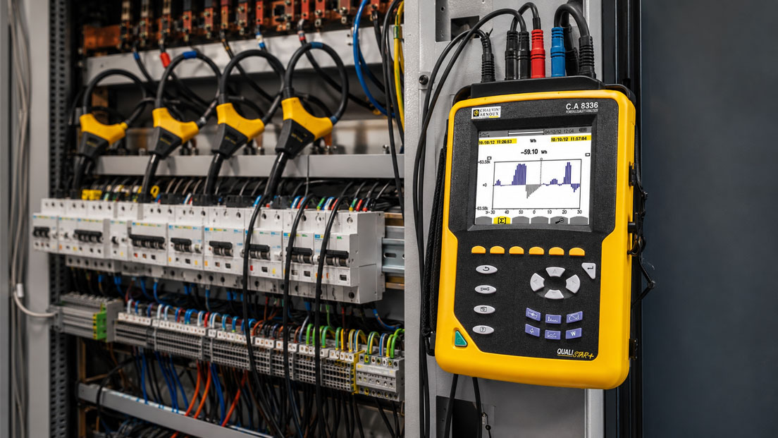
When machines fail sporadically, frequency converters display error messages, lighting flickers or control systems restart without an obvious reason, the cause is often first suspected in the machine itself. In many cases, however, the problem is not directly caused by the load, but by the electrical supply. Voltage dips, harmonics, flicker, unbalanced loads or short transients can disturb systems without being reliably detected with a simple multimeter.
Power quality describes how stable and disturbance-free the electrical energy supply is at a measuring point. It is not only a question of whether “230 V” or “400 V” are present. What matters is how voltage, current, frequency, harmonics, load distribution and events behave over time. Especially in industrial plants, building services, energy distribution systems, data centers, machine parks and production lines, power quality problems can have significant consequences.
This article explains which power quality parameters are important, how voltage dips, harmonics and flicker occur, why long-term measurement is often necessary and what to consider when selecting a power and energy analyzer.
Table of contents – measuring, analyzing and assessing power quality
- Why power quality is important in industry and building services
- What does power quality mean?
- Voltage dips: Short events with major impact
- Detecting overvoltages and transients
- Understanding harmonics and THD correctly
- Flicker: When voltage fluctuations become visible
- Unbalanced load in three-phase systems
- Assessing frequency, power factor and reactive power
- Measurement duration: Why instantaneous values are often not enough
- Connecting the power quality analyzer correctly
- Evaluation: Events, trends and reports
- Typical sources of interference in systems
- Practical example: Production system with sporadic faults
- Which measuring instruments / products are suitable?
- Conclusion: Power quality is a long-term issue, not an instantaneous value
- FAQ: Frequently asked questions about power quality measurement
Why power quality is important in industry and building services
Modern electrical systems contain more and more electronic loads. Frequency converters, switched-mode power supplies, LED lighting, UPS systems, chargers, machine controls, servers, photovoltaic inverters and power electronics change the current and voltage behavior in the grid. This creates loads and disturbances that are not always immediately visible with conventional measurement methods.
A system may appear stable during normal operation and still react sensitively to short events. A voltage dip of just a few milliseconds can cause a control system to restart. Harmonics can additionally heat transformers, cables or neutral conductors. Flicker can cause lighting to visibly fluctuate. Unbalanced loads can stress motors and unevenly load energy distribution systems.
For maintenance, energy management and plant planning, power quality is therefore an important diagnostic area. It helps clarify whether disturbances are caused by the load itself, by the internal distribution system, by other loads in operation or by the upstream supply.
Measurement becomes particularly relevant when disturbances occur only sporadically. A technician measuring on site with a multimeter may see completely normal voltage values. The actual voltage dip or harmonic load may only occur when a machine is switched on, when a compressor starts, when large loads are switched or at certain times of day. This is where power and energy analyzers with event recording are decisive.
| Symptom in the system | Possible power quality connection | Suitable measurement |
|---|---|---|
| Machine restarts sporadically | Voltage dip, interruption or transient | Event recording of voltage and supply. |
| Frequency converter reports an error | Grid feedback, voltage fluctuation or harmonics | Grid analysis with current, voltage, THD and events. |
| Lighting flickers | Flicker caused by load changes | Flicker and voltage fluctuation measurement. |
| Transformer becomes unusually warm | Harmonics or unbalanced load | Harmonic analysis and phase current comparison. |
| Neutral conductor is heavily loaded | Third harmonics or unbalanced loads | Current measurement per phase and neutral conductor analysis. |
What does power quality mean?
Power quality describes the properties of the electrical supply at a specific measuring point. It evaluates whether voltage, frequency and waveform remain within reasonable limits and whether disturbances occur that can affect loads. The term includes both slow changes and very short events.
A simple voltage value is not sufficient for this. A supply can have an average of 230 V or 400 V and still be problematic. If the voltage briefly dips during load changes, if the sinusoidal waveform is distorted by harmonics or if voltage fluctuations occur repeatedly, power quality may be insufficient for sensitive loads.
Power quality is also always location-specific. A measured value at the main connection can look different from a value at the end of a long feeder, directly at a machine or in a sub-distribution. The measuring point is therefore decisive. The closer the measurement is taken to the disturbed load, the better it can be assessed what this load actually sees.
For a complete assessment, voltage, current, frequency, power, power factor, harmonics, THD, flicker, transients, voltage dips, overvoltages and interruptions are typically recorded. Depending on the question, not all parameters are equally important.
| Power quality parameter | What is assessed? | Typical benefit |
|---|---|---|
| Voltage dip | Short-term reduction of the supply voltage | Cause of control system resets, drive errors or process interruptions. |
| Harmonics | Distortion of sinusoidal voltage or current | Assessment of grid feedback and additional heating. |
| THD | Total harmonic distortion | Compact key figure for assessing distortion. |
| Flicker | Recurring voltage fluctuations | Assessment of visible brightness fluctuations and load changes. |
| Unbalance | Uneven load or voltage between phases | Important for motors, distribution systems and transformers. |
| Transients | Very short voltage peaks | Indication of switching operations, lightning/overvoltage effects or EMC problems. |
Voltage dips: Short events with major impact
Voltage dips are short-term reductions of the supply voltage. They can be caused by large load starts, short circuits, switching operations, grid transfers, motor starts, compressors, welding systems or disturbances in the upstream grid. For many loads, not only the depth of the dip is decisive, but also its duration.
A voltage dip can be so short that it is not visible with a normal multimeter. Nevertheless, it can be enough to affect a PLC, frequency converter, control system or power supply unit. Particularly sensitive devices react even to short supply interruptions or significant voltage fluctuations.
During analysis, it is important to compare the time of the event with the system behavior. Does the voltage dip always occur when a large motor starts? Does it happen when a load is switched? Is there a connection with welding operations, compressors or elevators? Or does the event occur independently of internal switching operations and indicate the upstream supply instead?
A power quality analyzer with event recording can record voltage dips over time, document depth and duration and compare them with load profiles or current peaks. This turns an assumption into a reliable measurement.
| Possible cause | Typical characteristic | Test approach |
|---|---|---|
| Motor start | Short voltage dip with high inrush current | Record voltage and current during start-up. |
| Compressor or pump | Recurring events during load demand | Compare time stamps with system status. |
| Welding system | Voltage fluctuations in the rhythm of welding operations | Consider flicker and voltage dips together. |
| Grid transfer | Very short event with possible interruption | Use event recording with high time resolution. |
| Feeder too long or too weak | Voltage drop during load increase | Compare measurement at supply point and at load. |
Detecting overvoltages and transients
In addition to voltage dips, overvoltages and transients can also be problematic. Overvoltages are voltages above the normal range that can occur for longer or shorter periods. Transients are very short, fast voltage peaks caused, for example, by switching operations, inductive loads, grid transfers, lightning events or EMC influences.
Transients are difficult to detect with simple measuring instruments because they can be extremely short. Nevertheless, they can stress sensitive electronics, strain power supplies or cause communication problems. Especially in systems with large contactors, motors, solenoid valves, converters or long cables, fast voltage peaks can occur.
When assessing them, it is important to distinguish between one-off events and recurring patterns. A single transient can be caused by an exceptional event. Recurring transients often indicate switching operations or internal system causes.
A suitable power or power quality analyzer can record such events with time stamps. This is particularly helpful when disturbances occur sporadically and no conspicuous measured values are otherwise visible.
Understanding harmonics and THD correctly
Harmonics are frequency components that are multiples of the fundamental frequency. In a 50 Hz grid, for example, the 3rd harmonic is at 150 Hz, the 5th at 250 Hz and the 7th at 350 Hz. They are mainly caused by non-linear loads, i.e. loads that do not draw current sinusoidally.
Typical sources include frequency converters, switched-mode power supplies, LED drivers, UPS systems, rectifiers, chargers, electronic ballasts and power electronics. These devices are not fundamentally problematic, but if there are many of them or if the system structure is unfavorable, they can cause significant harmonic content.
Harmonics can additionally load cables, transformers, neutral conductors, capacitors and motors. They can cause heating, affect protective devices, trigger resonances or shorten the service life of components. It is particularly critical that a normal RMS value may still appear inconspicuous while the waveform is already significantly distorted.
THD stands for Total Harmonic Distortion and describes the total harmonic distortion. The THD value is a useful key figure, but it does not replace the individual assessment of the harmonics. For troubleshooting, it is often important to know which order is particularly strong. A dominant 5th or 7th harmonic indicates different relationships than a strong 3rd harmonic in the neutral conductor.
| Source | Typical effect | Measured variable |
|---|---|---|
| Frequency converter | Current harmonics, grid feedback, possible resonances | Current THD, voltage THD, individual harmonics. |
| Switched-mode power supplies | Non-sinusoidal current consumption | Current waveform and harmonic components. |
| LED lighting | Harmonics and possible flicker problems | Current harmonics and voltage fluctuations. |
| UPS systems | Interactions with grid and loads | Voltage, frequency, THD, events. |
| Many single-phase loads | Neutral conductor load and third harmonics | Neutral conductor current and 3rd harmonic. |
Flicker: When voltage fluctuations become visible
Flicker describes the effect of voltage fluctuations that can become noticeable particularly in lighting as brightness fluctuations. Common causes are loads that change their power consumption quickly or regularly. These include welding systems, large motors, elevators, presses, compressors, arc furnaces or other strongly fluctuating loads.
Flicker is not only a comfort issue. Visible flicker can indicate recurring voltage fluctuations that also stress other loads. In office buildings, production halls or public areas, flicker can also be disturbing and unpleasant for people.
The difficulty is that flicker often does not occur continuously. It is linked to specific operating states. A short measurement is therefore rarely sufficient. The measurement must cover the period in which the causing load is operating.
During analysis, flicker values should be considered together with load profiles and voltage fluctuations. If, for example, a welding system, a large drive or a machine operates cyclically, the relationship can often be traced via time stamps and trend curves.
Unbalanced load in three-phase systems
In an ideal three-phase system, the three phases are loaded evenly. In practice, this is rarely completely the case. Single-phase loads, unevenly distributed loads, different machine states or later system expansions can lead to unbalanced loading.
A certain degree of unbalance is normal in many systems. It becomes critical when individual phases are permanently loaded much more heavily or when the voltage between the phases becomes unequal. This can affect motors, transformers, cables and protective devices.
Especially in energy distribution systems with many single-phase loads, phase distribution should be checked. A high neutral conductor current can also indicate harmonic components, especially third harmonics. In that case, it is not enough to look only at the phase conductor currents.
A power quality analyzer enables simultaneous measurement of all phases. This allows current distribution, voltage level, phase angle, power and neutral conductor load to be evaluated together. Especially when troubleshooting in distribution systems, this overall view is much more meaningful than individual measurements.
Assessing frequency, power factor and reactive power
The grid frequency is normally very stable in public supply networks. In island grids, generator systems, emergency power systems or weak grids, however, it can fluctuate more strongly. Frequency deviations can be relevant for certain loads, drives or synchronization functions.
The power factor describes how effectively electrical power is used. A low power factor can be caused by reactive power, non-linear loads or an unfavorable system structure. This parameter is important for energy efficiency, transformer loading and grid planning.
Reactive power is not automatically a fault. Many inductive loads require reactive power. It becomes problematic when it leads to high currents, additional losses or unfavorable contractual and grid conditions. Compensation systems can help, but must be considered carefully when harmonics are present because resonances are possible.
A power and energy analyzer can record active power, apparent power, reactive power, power factor, energy consumption and load profiles. This makes it possible to assess not only power quality, but also the energetic use of a system.
Measurement duration: Why instantaneous values are often not enough
Power quality problems are often time-dependent. They occur when certain loads start, at the beginning of shifts, during high production load, during switching operations or at certain times of day. A measurement lasting only a few minutes can easily miss such events.
The suitable measurement duration depends on the question. If a fault occurs several times a day, a measurement over one or two days may be sufficient. If the problem is observed only once a week, recording must be correspondingly longer. For energy and load profile analyses, measurements over several days or a typical operating week are often useful.
It is important to link the measurement to the system operation. Time stamps alone are of limited help if it is not clear later which machine was running at that moment. Operating states, shift changes, production processes, fault messages and special events should therefore be documented in parallel.
For recurring disturbances, the measuring point should be chosen deliberately. A measurement at the main connection shows whether the entire system is affected. A measurement directly at the disturbed machine shows what voltage and current quality actually arrives there. In many cases, comparing several measuring points is particularly informative.
| Question | Suitable measurement duration | Important additional information |
|---|---|---|
| Sporadic machine fault | Until the fault occurs again | Document the time of the machine fault. |
| Load profile of a system | Typical operating week | Record shift times and production states. |
| Motor start or switch-on process | Targeted short-term measurement with event recording | Note start time and load state. |
| Flicker caused by cyclic loads | During typical load operation | Document the cycle of the causing load. |
| Harmonic analysis | During representative system load | Consider share of converters, power supplies and load states. |
Connecting the power quality analyzer correctly
A power quality measurement is only meaningful if the measuring instrument is connected and parameterized correctly. This includes voltage inputs, current clamps or current transformers, phase assignment, network type, measuring range, current transformer ratio and safety category.
For three-phase measurements, voltage and current of each phase must match. If the current transformer from L1 is accidentally assigned to the voltage path L2, power, power factor and phase angle can be calculated incorrectly. The current values themselves may still look plausible, while the power calculation is already wrong.
The direction of the current clamps is also important. Many current clamps have an arrow direction for power flow. If they are mounted the wrong way round, active power or power factor may appear implausible. With pure current measurement, this error is often not immediately noticeable.
Before starting a long-term measurement, a plausibility check should always be carried out. Are voltages and phase sequence correct? Are the currents realistic? Is active power positive? Does the power factor match the load? Are all channels displayed? This check prevents a multi-day measurement from becoming unusable due to a connection error.
| Connection point | Why important? | Typical error |
|---|---|---|
| Voltage inputs | Basis for events, power and grid assessment | Wrong phase or wrong network type connected. |
| Current clamps / transformers | Recording load, harmonics and power | Wrong direction or wrong transformer ratio. |
| Phase assignment | Required for correct power calculation | L1 voltage combined with L2 current. |
| Measurement category | Safety when working in distribution systems | Device or accessory not suitable for the place of use. |
| Measurement duration / memory | Recording rare events | Measurement ends before disturbance occurs. |
Evaluation: Events, trends and reports
The evaluation of a power quality measurement should not consist only of individual numerical values. The decisive factor is the combination of trends, events, time stamps, limit values and operating states. A diagram of voltage, current and power can quickly show whether a disturbance is related to a load change.
For voltage dips, depth, duration and time are important. For harmonics, THD and individual harmonics should be considered. For flicker, the timing relationship with changing loads is decisive. For unbalanced load, phase currents, phase voltages and neutral conductor must be evaluated together.
A good report should document the measurement conditions. This includes measuring location, network type, measurement period, connected current transformers, measuring device settings, load states, conspicuous events and a clear interpretation. Without this information, a measurement is difficult to trace later.
In practice, it is also important to distinguish between cause and effect. A power quality analyzer initially shows what happened electrically. Assessing why it happened requires knowledge of the system. The combination of measurement data, system diagram, operating log and experience is therefore decisive.
Typical sources of interference in systems
Many power quality problems are not caused by a single defect, but by the combination of several loads. A system is expanded, additional frequency converters are installed, LED lighting is retrofitted, machines start simultaneously or a new load is connected to an already heavily loaded sub-distribution. Only in combination do noticeable disturbances occur.
Frequency converters are a common part of modern systems and are technically very useful. Nevertheless, they can generate grid feedback if many devices work together or if filters, chokes or the grid structure do not match the application. Switched-mode power supplies and LED drivers can also contribute harmonics, especially when many of them are operated in one distribution system.
Large motors, compressors, pumps or transformers cause high inrush currents when switched on. These can lead to voltage dips. Welding systems, presses or arc processes can generate fast load changes that cause flicker or voltage fluctuations.
The infrastructure itself also plays a role. Long cables, cross-sections that are too small, loose terminals, uneven phase distribution, unsuitable compensation or aged components can intensify power quality problems.
| Source of interference | Typical power quality problem | Measurement approach |
|---|---|---|
| Frequency converter | Harmonics, grid feedback, EMC influences | Measure THD, individual harmonics, current and voltage profile. |
| Motor start | Voltage dip and high inrush current | Record inrush, voltage dip and start time. |
| Welding system | Flicker, voltage fluctuations, load jumps | Record flicker values and voltage trend. |
| LED lighting / switched-mode power supplies | Harmonics and non-linear current consumption | Check current harmonics and neutral conductor load. |
| Weak sub-distribution | Voltage drop during load changes | Compare measurement at supply point and at load. |
Practical example: Production system with sporadic faults
In a production hall, a packaging machine experiences faults several times per week. The control system reports supply voltage errors, but not regularly. During the first check with a multimeter, the voltages in the sub-distribution appear to be within the normal range. The machine itself also initially shows no abnormalities during operation.
Since the fault occurs sporadically, a power and power quality analyzer is connected directly to the sub-distribution of the affected machine for several days. Voltage and current of all three phases are recorded. In addition, event recording for voltage dips is activated. The operating times of the large loads in the hall are documented in parallel.
After evaluation, it becomes clear that the faults always occur when a large compressor starts and several machines in the production area start up at the same time. For a short time, the voltage at the affected sub-distribution drops significantly. The dip is too short to be reliably detected during a manual measurement, but it is sufficient to affect the control system of the packaging machine.
The measurement also shows that the voltage drop at the sub-distribution is greater than at the main supply point. This makes it clear that not only the compressor start, but also the internal distribution structure and cable length contribute to the disturbance. Based on the measurement data, targeted measures can be checked, such as adjusting load distribution, using a soft starter, providing a separate supply or improving cable routing.
The example shows why power quality measurements over time are so important. Without event recording, the fault would probably have continued to be attributed to the machine, although the cause was in the supply situation.
Which measuring instruments / products are suitable?
For measuring power quality, power, energy, harmonics, flicker and voltage dips, the category power and energy analyzers / energy recorders is the right starting point. It includes mobile measuring instruments and loggers for analyzing electrical systems, load profiles, grid parameters and power quality events.
For detailed power quality analyses, devices such as Qualistar power analyzers are of interest. Depending on the version, they can record voltage, current, power, energy, harmonics, flicker, transients, inrush currents and events. Such devices are particularly suitable for troubleshooting in industrial plants, energy distribution systems, building services and machine parks.
For long-term recording of load profiles and energy consumption, power and energy loggers can be useful. They are used when consumption, power, load peaks and operating states need to be documented over a longer period of time. For power quality questions, attention should be paid to which events, sampling rates and evaluation functions the respective device offers.
The main category electrical measuring and testing equipment is also relevant as a supplement. It includes other device areas such as current clamps, multimeters, VDE testers, voltage testers and accessories that can be used alongside power quality analysis depending on the measuring task.
The UPS4E loop calibrator is not the main instrument for this topic, but it can be useful as a supplement when 4–20 mA measuring chains need to be checked after a power quality analysis. In practice, a system fault may initially appear to be a grid problem, but may actually be caused by a faulty analog measuring chain, incorrect PLC scaling or a disturbed 4–20 mA signal. In that case, the UPS4E helps with loop checks, mA signal simulation and testing of transmitter, display and PLC input.
| Product / area | Typical use | Particularly relevant for |
|---|---|---|
| Power and energy analyzers / energy recorders | Analysis of voltage, current, power, energy and power quality | Harmonics, flicker, voltage dips, load profiles and energy analyses |
| Qualistar power analyzers | Detailed power quality and power analysis | Industrial plants, distribution systems, machine faults and event recording |
| Power and energy loggers | Long-term recording of load profiles and energy consumption | Energy audits, load peaks, consumption allocation and operating analysis |
| Electrical measuring and testing equipment | Supplementary electrical measurements and tests | Current measurement, voltage testing, system testing and troubleshooting |
| UPS4E loop calibrator | Testing and simulation of 4–20 mA signals | Supplementary loop check when process signals or PLC inputs may be a possible fault source |
Conclusion: Power quality is a long-term issue, not an instantaneous value
Power quality problems are often difficult to detect because they do not occur continuously. A multimeter can show normal values at the right moment, while shortly before a voltage dip, transient or load peak disturbed the system. This is why power and energy analyzers with long-term recording, event capture and evaluation software are so important for troubleshooting.
Voltage dips, harmonics, flicker, unbalanced load and transients can have different causes. The problem often results from the interaction of loads, distribution system, cable lengths and load states. A clean measurement helps replace assumptions with data.
For meaningful results, measuring point, measurement duration, connection, current transformers, network type and documentation must be correct. Only then can it be assessed whether the cause lies in the machine, in the internal distribution system, in a specific load or in the upstream supply. Anyone who measures power quality correctly creates the basis for targeted technical measures instead of unnecessary replacement of components.
FAQ: Frequently asked questions about power quality measurement
What does power quality mean?
Power quality describes how stable and disturbance-free the electrical supply is at a measuring point. Among other things, voltage, frequency, waveform, harmonics, flicker, voltage dips and transients are assessed.
Why is a multimeter not sufficient for power quality measurement?
A multimeter usually shows instantaneous values or slowly averaged values. Very short voltage dips, transients, harmonics or time-dependent events are often not reliably detected with it.
What is a voltage dip?
A voltage dip is a short-term reduction of the supply voltage. It can be caused by motor starts, large load changes, short circuits or switching operations and can disturb sensitive loads.
Why are voltage dips problematic?
They can affect control systems, power supplies, frequency converters or machines. Even short events can lead to restarts, error messages or process interruptions.
What are harmonics?
Harmonics are frequency components that are multiples of the fundamental frequency. They are mainly caused by non-linear loads such as frequency converters, switched-mode power supplies, LED drivers or rectifiers.
What does THD mean?
THD stands for Total Harmonic Distortion and describes the total harmonic distortion of voltage or current. The value helps to assess waveform distortion in a compact way.
Is a high current THD always critical?
Not automatically. The decisive factor is how strongly the current harmonics affect voltage, cables, transformers, neutral conductors and other loads. The entire system must be assessed.
What is flicker?
Flicker describes the effect of recurring voltage fluctuations, which can be visible as flickering lighting, for example. Common causes are strongly fluctuating loads.
Which devices frequently cause power quality problems?
Typical sources include frequency converters, switched-mode power supplies, large motors, compressors, welding systems, LED lighting, UPS systems, chargers and other power electronic loads.
How long should a power quality measurement last?
The measurement duration depends on the disturbance. If it occurs daily, a few days are often sufficient. For rare events, the measurement must be longer. It is important that the relevant operating state is captured.
Where should power quality be measured?
The measuring point depends on the question. Directly at the disturbed machine, you can see what arrives there. At the main supply point, you can identify whether the entire system is affected. Comparing several measuring points is often useful.
What is important for three-phase measurements?
Voltage and current paths must be assigned phase-correctly. In addition, current clamp direction, network type, current transformer ratio and measuring range must be set correctly.
Why is the current clamp direction important?
If the direction is wrong, active power, power factor or energy flow may be displayed incorrectly. The current values alone may still appear plausible.
What is a transient?
A transient is a very short voltage peak. It can be caused by switching operations, inductive loads, lightning events or EMC influences and can stress sensitive electronics.
What does unbalanced load mean?
Unbalanced load means that the three phases of a three-phase system are loaded to different degrees. This can lead to uneven heating, higher losses and problems with motors or distribution systems.
Why can the neutral conductor be heavily loaded?
A high neutral conductor current can be caused by unbalanced single-phase loads or certain harmonics. Especially many non-linear loads can additionally load the neutral conductor.
What role does the power factor play?
The power factor describes the ratio of active power to apparent power. It helps assess how electrical power is used and whether reactive power or distortion plays a role.
What should a power quality report include?
Important elements include measuring location, measurement period, network type, measuring instrument, current transformers, connection type, load states, events, diagrams, limit value assessment and a clear interpretation.
Can a power analyzer also measure energy consumption?
Yes. Many power and energy analyzers record not only power quality, but also power, energy consumption, load profiles and power factor. This makes them suitable for energy audits and load analysis as well.
When is the UPS4E useful for power quality problems?
The UPS4E is not the main instrument for power quality. It is useful as a supplement when 4–20 mA process signals, transmitters, displays or PLC inputs need to be checked as possible fault sources after the power quality measurement.