


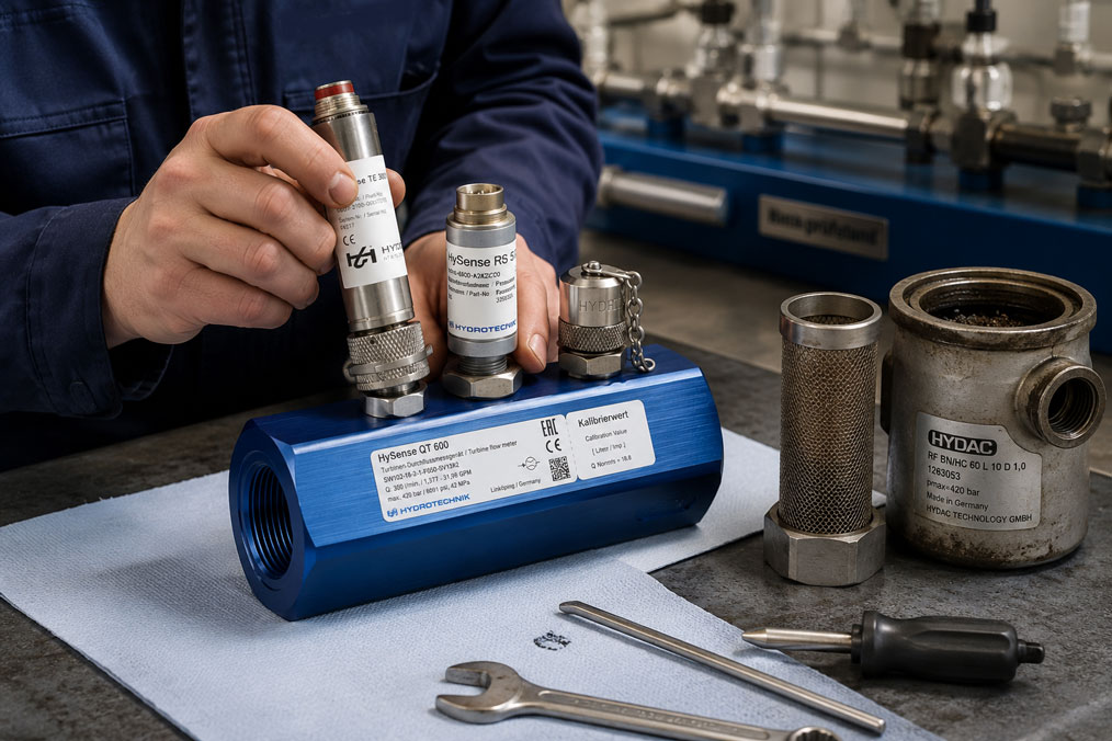
Turbine flow meters are precise mechanical flow meters. They measure volumetric flow via a freely rotating turbine wheel in the flow channel. Depending on the design, the rotational movement is processed as a pulse, frequency or analog output signal. To ensure reliable measurement, rotor, bearings, medium, installation situation and signal processing must work together properly.
Precisely because turbine flow meters operate with fine mechanical components, they are sensitive to particles, deposits, resinification, air bubbles, incorrect flushing procedures or unsuitable cleaning. A small particle in the bearing area, a deposit on the turbine wheel or changed friction can already cause the turbine flow meter to indicate values that are too low, respond sluggishly or, in the worst case, become blocked.
This article explains why cleaning and maintenance are so important for turbine flow meters, which symptoms indicate contamination, how particles and deposits affect the measurement and why filtration, flushing and a meaningful follow-up check are essential.
Table of contents
- Why turbine flow meters should be checked regularly
- How contamination affects the measuring principle
- Typical symptoms of contaminated or blocked turbine flow meters
- Particles in the medium: Why filtration is so important
- Bearings and turbine wheel: sensitive precision areas
- Deposits, resinification and sticky media
- Flushing before and after operation
- Cleaning the turbine flow meter: gentle rather than aggressive
- Why compressed-air cleaning can be critical
- Correctly designing filters, strainers and protective measures
- After cleaning: functional check and calibration
- Signal testing for pulse, frequency and 4–20 mA outputs
- Typical mistakes during maintenance and cleaning
- Practical example: Turbine flow meter in a hydraulic test bench indicates too little flow
- Which measuring instruments / products are suitable?
- Conclusion: Clean media are the best protection for turbine flow meters
- FAQ: Frequently asked questions about cleaning and maintaining turbine flow meters
Why turbine flow meters should be checked regularly
A turbine flow meter is not a purely electronic sensor, but a mechanical precision measuring instrument. The medium flows through the measuring channel and sets a turbine wheel in rotation. The rotational speed is related to the volumetric flow. If the mechanical conditions in the measuring channel change, the measuring behavior also changes.
In clean, suitable media, turbine flow meters can operate with very high precision and repeatability. In practice, however, media are not always ideal. Hydraulic oil may contain abrasion particles, flushing water may carry dirt, cooling lubricants may form residues, process liquids may crystallize, and particles may enter the line during installation or service work.
Regular maintenance therefore does not mean constantly dismantling the turbine flow meter. Much more important is targeted condition checking: Does the turbine rotate freely? Are the measured values plausible? Has the K-factor changed? Is there pressure loss, unusual noise, fluctuating signals or failure? Are filtration and medium still suitable for the application?
Well-planned maintenance protects not only the measuring instrument, but also process quality. When a turbine flow meter is contaminated, it often does not suddenly stop measuring altogether. The problem often starts gradually: the measured value drifts, the starting range worsens or low flows are no longer detected reliably.
| Maintenance objective | Why it is important | Typical benefit |
|---|---|---|
| Check free movement | Rotor and bearings must operate without increased friction | Prevention of low readings and blockages. |
| Avoid particles | Foreign bodies can damage bearings and turbine wheel | Longer service life and stable measured values. |
| Detect deposits | Coatings change flow behavior and rotor behavior | Early cleaning before significant measurement deviation occurs. |
| Plausibility-check the signal | Mechanics and evaluation must match | Faster distinction between mechanical and electrical faults. |
| Secure calibration status | Cleaning or wear can influence measuring behavior | Traceable measurement quality and documented accuracy. |
How contamination affects the measuring principle
In a turbine flow meter, the volumetric flow is linked to the rotational speed of the turbine wheel. This means that anything that affects the rotational movement can affect the measured value. This includes particles in the bearing area, deposits on the blades, viscous residues, mechanical damage, changed viscosity, air bubbles or disturbed flow.
If the rotor becomes more difficult to move, it rotates more slowly at the same flow rate. The output signal may then provide too few pulses or too low a frequency. The system interprets this as too low a flow, even though enough medium is actually flowing. Increased friction is particularly noticeable at low flow rates.
Deposits on the turbine wheel can also change the geometry. The rotor becomes heavier, more unbalanced or less favorable from a flow perspective. As a result, linearity can deteriorate. The turbine flow meter then does not indicate equally incorrectly across the entire measuring range, but behaves differently depending on the flow rate.
Particles that do not remain permanently in the sensor can also cause problems. They can briefly slow down the turbine wheel, damage bearings or make the signal unstable. For this reason, media cleanliness is a central issue with turbine flow meters.
Typical symptoms of contaminated or blocked turbine flow meters
A contaminated turbine flow meter often shows typical fault patterns. The measured value is too low, the sensor responds with a delay, the signal jumps, low flows are no longer detected or the turbine only starts at a higher minimum flow. In severe cases, the turbine wheel stops completely.
A common symptom is a gradual measuring error. At first, the system appears to operate normally, but the flow value increasingly deviates from reference values, pump curves or comparative measurements. This can be particularly problematic if the measured value is used for dosing, filling, test bench evaluation or process approvals.
With pulse or frequency outputs, irregular signals may occur. If the rotor does not rotate evenly, the pulse spacing can fluctuate. The evaluation then shows an unstable flow, even though the pump or process is actually operating steadily.
A complete blockage is usually easier to detect, but it is often already a late-stage fault pattern. In that case, the turbine flow meter shows no value or only a very low value despite flow being present. In this case, the evaluation should not simply be re-parameterized. First, it must be checked whether the turbine is mechanically free and whether medium, filtration and installation condition are suitable.
| Symptom | Possible cause | Test approach |
|---|---|---|
| Measured value too low | Rotor runs stiffly, bearing contaminated or deposits present | Check mechanical free movement and reference measurement. |
| No signal despite flow | Rotor blocked or signal pickup disturbed | Check mechanics and electrical output signal separately. |
| Strongly fluctuating display | Particles, air bubbles, pulsation or uneven rotor movement | Assess medium, filtration, venting and flow conditions. |
| Increased starting flow | Friction in bearings or contamination on rotor | Check especially in the lower measuring range. |
| Values no longer correct after cleaning | Mechanical damage, changed bearing behavior or incorrect assembly | Perform functional check and calibration if necessary. |
Particles in the medium: Why filtration is so important
Particles are among the most common causes of problems in turbine flow meters. They can originate from the medium itself, be generated by wear in pumps or valves, enter during installation work or be released from pipelines after modifications. Hard particles, metal abrasion, seal residues, chips, rust, sand or fibers are particularly critical.
In a turbine flow meter, the medium flows directly through the measuring channel and past the turbine wheel. Particles can enter the space between rotor and housing, the bearing area or the blades. Even small foreign bodies can increase friction or briefly block the turbine wheel.
Filtration is therefore not just a general cleanliness issue, but part of measuring point planning. A suitable filter or strainer upstream of the turbine flow meter can significantly reduce the risk. The filter fineness must match the turbine flow meter, medium and application. Filters that are too coarse do not provide enough protection, while filters that are too fine can quickly clog and generate pressure loss.
It is also important to monitor and regularly maintain the filter itself. A clogged filter can limit flow, increase pressure loss and indirectly affect the measurement. The turbine flow meter is then protected, but the system no longer operates in the intended condition.
Bearings and turbine wheel: sensitive precision areas
The turbine wheel and its bearings are the most sensitive areas of a turbine flow meter. They must operate smoothly while remaining mechanically stable. Any additional friction changes starting behavior and measuring accuracy. For this reason, rough mechanical work should never be carried out on these components.
Special care is required during cleaning. Scraping, brushing with hard tools, turning with screwdrivers or levering out particles can damage the turbine wheel. Even apparently minor damage can affect balance, geometry or bearings.
If the rotor does not move freely, the cause should be investigated systematically. Is there a foreign body in the measuring channel? Are there resinified residues? Is a bearing damaged? Was the turbine flow meter operated with excessive pressure or unsuitable medium? Are there signs of corrosion or chemical attack?
Depending on the design and manufacturer’s instructions, turbine flow meters may be opened or cleaned to different extents. Without clear service instructions, a turbine flow meter should not be dismantled arbitrarily. With precision measuring instruments, improper disassembly can make subsequent calibration or even replacement necessary.
Deposits, resinification and sticky media
Not only solid particles can impair turbine flow meters. Deposits and resinification are also critical. They can be caused, for example, by ageing oils, sticky process media, residues from additives, crystallization, precipitation, drying of media residues or incomplete flushing after operation.
Deposits often have a gradual effect. The turbine wheel may still rotate initially, but with increased friction. The measured value becomes worse in the lower range, repeatability decreases and the signal becomes more unstable. If the medium hardens or sticks after standstill, the turbine flow meter can be completely blocked at the next start.
Applications in which media remain in the turbine flow meter after the process are particularly critical. If the medium cools down, thickens, crystallizes or dries, residues form on the rotor, bearings or measuring channel. For such applications, a suitable flushing and draining concept should therefore be provided.
The cleaning method must match the medium and the material of the turbine flow meter. A solvent that removes deposits effectively may attack seals, bearing materials or housing material. Media compatibility should therefore always be checked. In case of doubt, consulting the manufacturer or supplier is more sensible than attempting aggressive cleaning.
Flushing before and after operation
Flushing is one of the most important measures for keeping turbine flow meters clean. Before commissioning, a line may contain particles, installation contamination, seal residues or metal chips. If these are flushed directly through the turbine flow meter, the measuring instrument can already be damaged during its first use.
For this reason, a new or modified line should ideally be flushed before the turbine flow meter is installed. Alternatively, a bypass solution or temporary protection can be provided. Only when the line is clean should the turbine flow meter be put into measuring operation.
After operation, flushing is especially important if the medium tends to form deposits. Suitable flushing media can remove residues before they dry, crystallize or resinify. The flushing medium must be compatible with the turbine flow meter, the seals and the subsequent process.
The flushing direction and flushing pressure should also be considered. A turbine flow meter is designed for defined flow conditions. Very high flow velocities, pressure surges or unsuitable reverse flushing can cause mechanical stress. If reverse flushing is required, it should be checked whether the particular turbine flow meter is suitable for it.
| Situation | Sensible measure | Important to consider |
|---|---|---|
| New pipeline or hose section | Flush thoroughly before installing the turbine flow meter | Installation residues must not pass through the turbine. |
| Medium prone to deposits | Flush with suitable medium after operation | Flushing medium must be compatible with materials and process media. |
| Long standstill | Drain or preserve turbine flow meter | Residues can harden or cause corrosion. |
| Restarting operation | Check free movement and signal plausibility | Do not immediately trust measured values after long standstill. |
Cleaning the turbine flow meter: gentle rather than aggressive
Cleaning a turbine flow meter should always be carried out carefully and traceably. The aim is not to work on the device as aggressively as possible, but to remove residues without damaging rotor, bearings, seals or signal pickup. The first step is therefore a visual inspection, insofar as the design allows it.
If the turbine flow meter is removed, it should be placed on a clean surface and protected against impacts. Connection openings should not lie unprotected in a dirty environment. Foreign bodies introduced during cleaning can later be just as problematic as the original contamination.
Suitable cleaning media depend on the process medium. For water-based media, flushing with water or a suitable cleaning medium may be useful. For oil or hydraulic media, a compatible flushing oil or suitable cleaning medium may be required. For chemical media, material compatibility must be checked particularly carefully.
Mechanical cleaning should only be carried out with great restraint. Gentle flushing, soaking or careful removal of loose residues is usually better than aggressive scraping. If particles are firmly lodged in the bearing area or the rotor cannot be freed, professional service inspection is more sensible than risky in-house repair.
Why compressed-air cleaning can be critical
Compressed air is often used spontaneously for cleaning in workshops. With turbine flow meters, this can be problematic. If the turbine wheel is driven very quickly by compressed air, it can rotate much faster than during normal measuring operation. This can mechanically stress or damage bearings and rotor.
In addition, compressed air can push particles deeper into bearing areas instead of flushing them out. If the compressed air is not clean and dry, oil, water or new particles can also be introduced. A blow gun is therefore not a substitute for proper cleaning.
“Blowing free” a blocked turbine flow meter with high pressure is especially critical. If the rotor suddenly starts moving or a foreign body is shot through the measuring channel, sensitive components can be damaged. The signal behavior after such stress can also change without the damage being visible from the outside.
If compressed air is used at all, it should only be used very carefully, with reduced pressure and according to the manufacturer’s instructions. In many cases, flushing with a suitable medium is the better and more controlled method.
Correctly designing filters, strainers and protective measures
The best cleaning is cleaning that is never needed in the first place. This is why filtration upstream of the turbine flow meter is a central protective factor. A filter or strainer before the measuring instrument can retain particles before they reach the rotor or bearings.
Filter fineness should not be selected generically. It must match the turbine flow meter, medium, flow rate, viscosity and permissible differential pressure. Hydraulic oil has different requirements than water, fuel, coolant or process liquids. Temperature also influences viscosity and pressure loss.
A filter only provides reliable protection if it is maintained. A clogged filter can reduce flow, promote cavitation, stress pumps or influence process pressure. For critical applications, differential pressure across the filter or a defined maintenance interval should therefore also be provided.
In addition to filtration, further protective measures may be useful. These include clean installation, flushed lines, bypass during flushing, venting, avoidance of pressure surges, suitable installation position, protection against vibration and clean media routing without unnecessary dead spaces.
| Protective measure | Benefit | Limit of the measure |
|---|---|---|
| Filter upstream of turbine flow meter | Reduces particles in the measuring channel | Must match the application and be maintained regularly. |
| Strainer | Retains coarse particles and installation contamination | Does not necessarily protect against fine particles. |
| Flush line before commissioning | Removes installation and pipeline residues | Should preferably be done before installing the turbine. |
| Venting | Reduces air bubbles and unstable signals | Does not replace clean media routing. |
| Pressure surge prevention | Protects rotor, bearings and connections | Requires suitable valve and pump control. |
After cleaning: functional check and calibration
After cleaning, the turbine flow meter should not simply be reinstalled and put back into operation without checking. First, it should be checked whether the rotor runs freely, whether there is no visible damage, whether sealing surfaces are clean and whether the electrical connection has been restored correctly.
A functional check is then recommended. The turbine flow meter is operated with a suitable medium and a known or plausible flow rate. The output signal should be stable and match the expected flow. With pulse or frequency outputs, it should be checked whether the signal sequence is uniform.
If the turbine flow meter is used for quality-relevant measurements, test benches, dosing or filling, calibration or at least a comparative measurement against a suitable reference should be carried out after cleaning. Cleaning can remove residues, but it can also reveal that bearings or rotor are already worn.
Documentation is particularly important. If a turbine flow meter has been cleaned, it should be recorded why the cleaning was performed, which residues were found, which cleaning medium was used, whether the rotor ran freely and whether a follow-up check or calibration was carried out.
Signal testing for pulse, frequency and 4–20 mA outputs
After cleaning, a distinction must be made between mechanical and electrical testing. A mechanically clean turbine flow meter only delivers correct values if signal pickup, cable, evaluation unit and parameterization are also correct. Conversely, an electrical fault can look like a turbine problem.
With classic turbine flow meters with pulse or frequency output, it must be checked whether the pulses are detected cleanly, whether the K-factor is stored correctly and whether the frequency matches the flow. If an evaluation shows incorrect values after cleaning, the cause is not automatically mechanical. Scaling, input card, cable break, shielding or parameterization can also play a role.
For turbine flow meters or transmitters with an analog 4–20 mA output, the current loop must also be checked. In such cases, the UPS4E loop calibrator can be useful. It can measure or simulate mA signals and helps evaluate transmitter, wiring, display and PLC input separately.
For pure pulse or frequency signals, however, the UPS4E is not the main instrument. Suitable frequency counters, pulse counters, process calibrators or the respective evaluation device are relevant here. The decisive factor is to test the signal in accordance with the output type of the turbine flow meter.
Typical mistakes during maintenance and cleaning
Many turbine flow meter damages do not occur during normal measuring operation, but during installation, cleaning or recommissioning. Particularly critical are improper mechanical interventions on the turbine wheel, excessive pressure during cleaning, unsuitable solvents or missing filtration after reinstallation.
A common mistake is trying to make a blocked turbine flow meter “move freely” with a tool. This can damage rotor, bearings or measuring channel. Even if the turbine wheel rotates again afterwards, it is not certain that the turbine flow meter still measures correctly.
Another mistake is cleaning without root-cause analysis. If the turbine flow meter is contaminated, it must be asked where the contamination comes from. Is it due to installation particles, the medium, missing filtration, residues after standstill or an unsuitable process? Without this clarification, the problem will usually occur again.
Calibration is also often forgotten. A cleaned turbine flow meter is not automatically back within specification. Especially in precision applications, it should be checked after cleaning, repair or abnormal behavior whether the measurement deviation remains acceptable.
| Mistake | Possible consequence | Better approach |
|---|---|---|
| Moving the rotor with a tool | Damage to bearings or turbine wheel | Clean only according to manufacturer instructions and do not use hard tools. |
| Blowing free with high-pressure compressed air | Overspeed, bearing stress or particle displacement | Flush gently and use compressed air only in a controlled manner. |
| Using the wrong solvent | Seals, bearings or housing are attacked | Check material compatibility before cleaning. |
| Filter not maintained | Renewed contamination or pressure loss | Define filter condition checks and maintenance interval. |
| No check after cleaning | Incorrect measured values remain undetected | Perform functional check and calibration if required. |
Practical example: Turbine flow meter in a hydraulic test bench indicates too little flow
In a hydraulic test bench, the volumetric flow is monitored using a turbine flow meter. After several months of operation, it becomes noticeable that the displayed flow at identical pump settings is lower than before. The pump appears to operate normally, and pressure and temperature are within the usual range. Initially, an error in the evaluation is suspected.
During the check, however, it becomes clear that the frequency signal of the turbine flow meter is stable but too low. After removal, slight contamination is found in the measuring channel. In addition, fine particles are present in the area of the upstream filter. The rotor is not completely blocked, but no longer runs as freely as expected.
The turbine flow meter is carefully flushed with a suitable medium. Aggressive mechanical cleaning and high-pressure compressed air are avoided. The filter is replaced and the line is flushed before recommissioning. The turbine flow meter is then reinstalled and compared with a known flow range.
The follow-up check shows that the measured value is much more plausible again. At the same time, it is decided to shorten the filter maintenance interval and to always flush upstream of the turbine flow meter after service work on the hydraulic system. It is also documented that the turbine flow meter should be calibrated at the next regular maintenance after cleaning.
The example shows that a contaminated turbine flow meter does not necessarily fail immediately. Often, a gradual measurement deviation occurs first. Anyone who only checks the electronics will then overlook the mechanical cause.
Which measuring instruments / products are suitable?
For applications with precise volumetric flow measurement, the turbine flow meters category is the right starting point. Turbine flow meters are particularly suitable for defined media and applications where a mechanical measuring principle with pulse, frequency or analog evaluation is useful.
The main category flow measurement technology is helpful when checking whether a turbine flow meter is still the right measuring principle or whether another method is better suited to the application. With heavily contaminated, viscous, abrasive, crystallizing or strongly varying media, another flow measurement principle may sometimes be more robust.
When maintaining turbine flow meters, suitable filters, strainers, flushing options and, if necessary, reference measurements should also be considered. The decisive factor is not only the measuring instrument itself, but the complete measuring point consisting of medium, line, filtration, installation situation, evaluation and maintenance concept.
If a turbine flow meter or downstream transmitter outputs a 4–20 mA signal, the UPS4E loop calibrator can help with electrical testing. It is particularly useful when it needs to be clarified after cleaning or maintenance whether the fault lies in the transmitter, wiring, display or PLC input. For pure pulse or frequency outputs, however, a suitable test instrument for frequency or pulse signals should be used.
| Product / area | Typical use | Particularly relevant for |
|---|---|---|
| Turbine flow meters | Mechanical volumetric flow measurement via turbine wheel | Test benches, hydraulics, dosing, filling and process measurement |
| Flow measurement technology | Selection of suitable flow measurement principles | Comparison of turbine, MID, ultrasonic, Coriolis, vortex and other methods |
| Filters / strainers | Protection of turbine wheel and bearings | Particle-loaded media, hydraulic systems and after installation work |
| Reference measurement / calibration | Checking measurement deviation after cleaning or maintenance | Quality-relevant measuring points, test benches and dosing applications |
| UPS4E loop calibrator | Testing of 4–20 mA signals | Turbine flow meters with analog output or downstream transmitters |
Conclusion: Clean media are the best protection for turbine flow meters
Turbine flow meters can operate very precisely and reliably when medium, installation, filtration and maintenance match the application. At the same time, they react sensitively to particles, deposits, resinified media, incorrect cleaning and mechanical damage. Cleaning should therefore not be understood as an occasional emergency measure, but as part of a clean maintenance concept.
The most important protective measure is suitable media conditioning. Filters, strainers, flushed lines and a well-thought-out standstill and flushing concept prevent many problems in advance. If a turbine flow meter is contaminated, it should not only be cleaned, but the cause of the contamination should also be identified.
After cleaning or abnormal behavior, a functional check is important. For precise or quality-relevant measuring points, additional calibration or comparative measurement should be carried out. Only then can it be ensured that the turbine flow meter not only rotates again, but also measures correctly again.
FAQ: Frequently asked questions about cleaning and maintaining turbine flow meters
Why are turbine flow meters sensitive to particles?
Turbine flow meters have a freely rotating turbine wheel and precision bearings. Particles can slow down the movement, damage bearings or block the turbine wheel. This directly changes the measuring signal.
How do you recognize a contaminated turbine flow meter?
Typical indications are measured values that are too low, fluctuating signals, delayed response, increased starting flow or no signal despite flow being present.
Can a turbine flow meter be partially blocked?
Yes. The rotor may still rotate, but be stiff due to deposits or particles. The turbine flow meter then often shows values that are too low or unstable.
Is it allowed to move the turbine wheel with a tool?
This is not recommended. Hard tools can damage rotor, bearings or measuring channel. A turbine flow meter should only be cleaned according to the manufacturer’s instructions and very carefully.
Can a turbine flow meter be cleaned with compressed air?
Compressed air can be critical because the turbine wheel can rotate uncontrollably at very high speed. This can stress bearings and rotor. If compressed air is used, it should only be used in a controlled manner, with reduced pressure and according to the manufacturer’s instructions.
What role does the filter upstream of a turbine flow meter play?
A suitable filter protects turbine wheel and bearings from particles. It is one of the most important measures for preventing contamination and mechanical damage.
How fine does the filter need to be?
Filter fineness depends on the turbine flow meter, medium, flow rate, viscosity and permissible pressure loss. It should not be selected generically, but adapted to the specific application.
Can a filter that is too fine cause problems?
Yes. A filter that is too fine or clogged can generate pressure loss, limit flow or affect the system. For this reason, the filter must be checked and maintained regularly.
Should a line be flushed before installing a turbine flow meter?
Yes. New or modified lines can contain chips, seal residues, rust or installation contamination. These particles should not be flushed through the turbine flow meter.
When is flushing after operation useful?
Flushing is especially useful for media that can resinify, crystallize, dry, stick or form deposits. This removes residues before they can impair the rotor.
Which cleaning medium should be used?
This depends on the process medium and the materials of the turbine flow meter. The cleaning medium must dissolve deposits, but must not attack seals, bearings or housing.
Can cleaning influence calibration?
Yes. Cleaning can remove residues, but it can also show that rotor or bearings are already worn. In quality-relevant applications, calibration or comparative measurement should be carried out after cleaning.
Why does the turbine flow meter still show incorrect values after cleaning?
Possible causes include remaining contamination, mechanical damage, worn bearings, incorrect installation, wrong K-factor or an electrical fault in the evaluation.
What is the K-factor of a turbine flow meter?
The K-factor describes how many pulses correspond to a specific volume unit. If the K-factor is stored incorrectly in the evaluation, flow and quantity are calculated incorrectly.
How do you test a turbine flow meter after cleaning?
First, the mechanical free movement should be checked. The turbine flow meter should then be operated with a suitable medium and the output signal compared with a plausible or known flow.
What should be done if the turbine flow meter is blocked?
The turbine flow meter should be taken out of service and checked carefully. Do not loosen it by force. Determine the cause of the blockage, perform suitable cleaning and arrange service or calibration if required.
Which media are critical for turbine flow meters?
Media with particles, abrasive components, crystallization, resinification, high viscosity, sticky residues or chemical attack on materials can be critical.
Are turbine flow meters suitable for heavily contaminated media?
In many cases, heavily contaminated media are unfavorable for turbine flow meters. It should then be checked whether filtration is sufficient or whether another flow measurement principle is more suitable.
When is the UPS4E useful with turbine flow meters?
The UPS4E is useful when a turbine flow meter or downstream transmitter provides a 4–20 mA signal. The current loop can then be tested or simulated. For pure pulse or frequency outputs, another test instrument is required.
When should a turbine flow meter be replaced?
Replacement can be useful if rotor or bearings are damaged, repeated blockages occur, calibration is no longer maintained or the medium is permanently unsuitable for the turbine flow meter.