


A precision pressure controller is to automatically calibrate pressure sensors up to 20 bar. Both a nitrogen cylinder and the plant compressed-air network are available in the laboratory. Both sources can provide the required pressure. Does this mean that both are equally suitable for calibration?
Not necessarily. For pneumatic pressure calibration, the maximum supply pressure is not the only relevant factor. The pressure medium flows through regulators, valves, manifolds, the reference sensor and the device under test. Water, oil, particles or corrosive components can therefore impair the function of the calibration system and, over time, lead to drift, unstable control or damage.
The supply itself must also be suitable for the calibration task. A pressure controller requires sufficient pressure reserve and gas flow to bring the connected device under test quickly to the setpoint. A supply line that is too small or a pressure regulator that excessively restricts flow can cause an otherwise highly accurate controller to operate slowly or unstably.
Nitrogen is therefore not automatically more accurate than compressed air. The decisive factor is the quality of the pressure medium. Dry, oil-free and adequately filtered compressed air can be very suitable for many calibration tasks. Cylinder nitrogen, however, often offers the advantage of a particularly clean, dry and reproducible supply.
What is the function of the pressure medium in pneumatic calibration?
In pneumatic calibration, a gas is used to transfer the required test pressure from the pressure generator or pressure controller to the device under test.
A typical setup is:
Gas supply → pressure regulator → pressure controller → device under test
The pressure controller regulates the gas pressure to defined setpoints.
An internal or external reference sensor measures the actual applied pressure.
At each calibration point, the value of the device under test is then compared with the reference.
The supply gas comes into contact with numerous components:
- supply lines,
- pressure regulators,
- filters,
- control valves,
- manifolds,
- reference sensor,
- test hoses,
- device under test.
The quality of the gas therefore affects not only the device under test but the entire pneumatic calibration system.
Nitrogen or compressed air – which is generally better?
For many pneumatic pressure calibrations, both:
dry compressed air
and:
nitrogen N₂
can be used.
The decisive factor is that the measuring or pressure medium used is within the specifications of both the calibration instrument and the device under test.
From a metrological point of view, a pressure of:
10.000 bar
initially exerts the same mechanical pressure on the sensor diaphragm, regardless of whether it is generated using dry air or nitrogen.
The main differences are:
- cleanliness,
- residual moisture,
- possible oil contamination,
- particle contamination,
- availability,
- cost,
- supply stability.
The question is therefore less:
Which gas is more accurate?
and more:
Which gas supply can continuously provide the required quality for this measuring point?
What are the advantages of nitrogen?
Cylinder nitrogen is frequently used for high-quality pneumatic calibration systems.
A key advantage is that suitable cylinder nitrogen normally provides a defined and very clean gas supply.
Typical advantages include:
- low moisture content,
- no compressor oil from a plant compressed-air network,
- low particle contamination,
- consistent gas quality,
- independent supply from the plant compressed-air network.
This makes nitrogen particularly attractive for:
- calibration laboratories,
- high-quality pressure controllers,
- low measurement uncertainties,
- test benches used only occasionally,
- contamination-critical applications.
However, nitrogen also has disadvantages.
Cylinders must be:
- provided,
- secured safely,
- replaced regularly,
- operated with a suitable pressure regulator
.
With high gas consumption, a cylinder supply can also be less economical than a central dry compressed-air supply.
When is compressed air suitable?
A central compressed-air supply can be a very economical solution for pneumatic calibrations.
This applies particularly in cases of:
- regular operation,
- high gas consumption,
- large test volumes,
- automated production test benches.
However, not every existing plant compressed-air supply is automatically suitable as calibration gas.
An industrial compressed-air system may contain, for example:
- residual moisture,
- oil aerosols,
- compressor wear particles,
- corrosion particles from pipework,
- condensate,
- contamination from the distribution network.
Even with an oil-free compressor, the quality should be assessed at the actual connection point of the calibration station.
There may be many metres of pipework, filters, vessels and fittings between the compressor and the test bench.
Suitability is not determined by the description “compressed air” or “oil-free compressor”, but by the gas quality actually available at the test bench.
Why is the cleanliness of the supply gas so important?
Modern automatic pressure controllers contain very precisely operating control valves.
These valves must continuously meter small quantities of gas in order to maintain the required pressure at a stable level.
Contamination can:
- damage valve seats,
- contaminate sealing surfaces,
- block small flow passages,
- increase leakage,
- impair control performance.
A controller may then, for example, require more time to reach a setpoint.
In an unfavourable case, the pressure value may appear unstable even though the actual reference measurement system is still operating correctly.
Clean supply gas is therefore a prerequisite for reproducible control and a long service life of the pneumatic components.
Why is oil particularly problematic?
Oil can enter the gas supply through compressors, lubricants or a contaminated compressed-air network.
It may be present as:
- liquid oil,
- oil aerosol or
- oil vapour
.
Deposits on precision control valves and sealing surfaces are particularly problematic.
This can permanently change the control performance of a pressure controller.
Oil can also be transported from the calibrator to the connected device under test.
On a test bench used to calibrate different devices, this can result in undesirable cross-contamination.
For high-quality pneumatic pressure controllers, a dry and oil-free gas supply should therefore generally be used unless the instrument manufacturer explicitly approves otherwise.
What effects do particles have?
Particles can originate from various sources.
Examples include:
- compressor wear,
- corrosion in the pipework network,
- sealing material,
- installation residues,
- PTFE tape,
- dust from open connections.
Small particles that reach control valves and sensor connections are particularly critical.
Even a single foreign particle on a valve seat can prevent the valve from closing completely.
Possible consequences include:
- slow pressure drift,
- increased gas consumption,
- unstable control,
- extended stabilization times.
The pneumatic installation should therefore be handled with the same degree of cleanliness during assembly as the measurement equipment itself.
Why must moisture be considered?
Water is also an undesirable contaminant in a pneumatic calibration supply.
It may be present as water vapour or liquid condensate.
Moisture becomes particularly problematic in connection with:
- pressure changes,
- temperature changes,
- cold pipework,
- significant pressure reduction.
Under unfavourable conditions, water vapour can condense.
Liquid water should not enter the pneumatic components of a pressure controller intended for use with dry gases.
Moisture can also promote corrosion in lines and connections.
Controlled drying of the compressed air is therefore considerably more important than merely installing a water separator directly at the compressor.
What does the pressure dew point indicate?
The pressure dew point is commonly used to assess the residual moisture content of compressed air.
In simplified terms, it describes the temperature at which moisture contained in the compressed gas begins to condense under the specified pressure conditions.
The lower the pressure dew point, the drier the gas.
For precision pressure controllers, the specific requirements of the instrument manufacturer should be used.
A general statement such as:
workshop compressed air is dry enough
is therefore not sufficient.
Instead, the following should be checked:
- type of dryer,
- achieved pressure dew point,
- condition of the filters,
- actual quality at the calibration station.
Can condensation occur during pressure reduction?
When a gas is controlled and expanded, both pressure and temperature change.
Rapid pressure changes in particular can cause local temperature changes.
If the supply gas already contains a high moisture level, this can increase the risk of condensation.
Condensate can accumulate, for example, in:
- low points in supply lines,
- filters,
- pressure regulators,
- hoses.
A calibration supply should therefore not attempt to condition heavily moisture-laden compressed air only immediately before the controller.
Suitable central or local drying is preferable.
What type of filtration is appropriate?
The required air treatment depends on the available gas supply.
For compressed air, treatment may consist of several stages, for example:
Compressed-air network → water separation → particle filter → coalescing filter → drying → fine filter → pressure controller
The specific filter combination must be appropriate for the quality of the available compressed air and the manufacturer’s requirements for the controller.
It is also important to remember:
Every filter creates a pressure drop.
Very fine filtration using filter elements that are too small can therefore restrict the available gas flow.
Filters should be selected with regard to both:
- separation performance and
- flow capacity
.
How high must the supply pressure be?
An automatic pressure controller can only generate pressure if its positive supply pressure is higher than the required output pressure.
For a required test pressure of:
20 bar
a supply of exactly:
20 bar
is therefore normally insufficient.
The controller requires a pressure differential across its internal control valves.
The necessary reserve is specified by the instrument manufacturer.
For the PACE series, for example, the supply gas pressure is intended to be approximately:
10% above the maximum required output pressure
.
Different requirements may apply to other pressure controllers.
Why does a pressure controller require pressure reserve?
A control valve adjusts gas flow by means of a pressure differential.
The smaller the difference between supply pressure and required output pressure, the less gas can flow through the valve.
This can result in:
- slower pressure generation,
- longer time to reach the setpoint,
- poorer dynamic control behaviour.
This becomes particularly noticeable with:
- large device-under-test volumes,
- long hoses,
- large pressure steps.
However, the supply pressure should not be increased arbitrarily.
The maximum permissible supply and operating pressures of all components must be observed.
Why is the available gas flow important?
A stable static supply pressure alone does not fully describe the performance of the gas supply.
When a large device under test is pressurized, the controller temporarily requires a significant gas flow.
If, for example:
- the supply line is too small,
- the pressure regulator is too small,
- a filter is blocked or
- a quick coupling causes excessive restriction,
the supply pressure directly at the controller may drop during the control process.
Once the test pressure has been reached, it may rise again.
Such a supply can appear completely normal while the system is at rest.
It should therefore be assessed under actual gas-flow conditions.
When does an additional reservoir help?
For large test volumes or a limited central compressed-air supply, a local compressed-air reservoir can improve dynamic supply performance.
The reservoir is installed as close as possible to the pressure controller and serves as a pneumatic energy store.
During a rapid pressure increase, the controller can initially draw gas from this local volume.
The more remote supply then refills the reservoir.
Such a buffer can be particularly useful when long supply lines limit the available peak flow rate.
However, it does not replace an adequately sized and clean basic supply.
What is the function of the cylinder pressure regulator?
A full nitrogen cylinder has a considerably higher pressure than a typical calibration controller requires.
A suitable pressure regulator is therefore required between the cylinder and the controller.
It must:
- be suitable for the cylinder pressure,
- provide the required outlet pressure,
- allow sufficient gas flow,
- be compatible with nitrogen.
A pressure regulator that is too small can become the limiting factor even when the cylinder itself is sufficiently full.
As the cylinder pressure decreases, it should also be checked whether sufficient pressure reserve remains available for the highest calibration point.
What influence does gas temperature have?
A gas also changes temperature when its pressure changes.
During rapid compression, the gas may initially heat up.
During expansion, it may cool down.
After a rapid pressure step, the:
- gas,
- device under test,
- hoses,
- adapters
are therefore not immediately in thermal equilibrium again.
During the subsequent temperature equalization, the pressure can change even though the system is completely leak-tight.
This effect is particularly important in pneumatic calibration.
Why is stabilization required after a pressure change?
After every new pressure point, the measuring setup requires time to reach a stable condition.
During stabilization, several processes can occur simultaneously:
- control to the setpoint,
- temperature equalization of the gas,
- mechanical settling effects in the device under test,
- electronic filtering of the measurement signal.
A measured value should therefore not automatically be recorded the moment the controller first reaches the setpoint.
A suitable acceptance criterion can, for example, be based on a maximum permissible pressure change within a defined time window.
The specific criterion must be appropriate for the required measurement uncertainty and the device under test.
Longer stabilization cannot correct a poor test setup, but it prevents normal thermodynamic equalization processes from being incorrectly interpreted as measurement deviations.
Can the device under test contaminate the calibrator?
Contamination can enter the pressure controller not only from the gas supply.
The device under test itself can also be a source.
A pressure transmitter that has previously been in contact with:
- oil,
- water,
- hydraulic fluid,
- process medium
may contain residual medium in its pressure connection.
If this device is connected directly to a pneumatic controller, the medium may be transported back towards the calibration system during pressure changes.
This is particularly critical for sensitive precision valves.
Before connection, it should therefore be checked whether the device under test is suitable for clean pneumatic calibration and has been adequately cleaned or dried.
For contamination-critical devices under test, suitable separation or protective measures may be required depending on the application.
Does nitrogen influence measurement uncertainty?
Nitrogen does not inherently produce lower pressure measurement uncertainty than clean, dry compressed air.
The main contributions to the measurement uncertainty of a pressure calibration include, for example:
- accuracy or calibration uncertainty of the reference,
- long-term stability of the reference,
- resolution,
- repeatability,
- pressure stability,
- temperature conditions,
- height difference between the reference and the device under test.
The supply gas usually has an indirect influence.
Contaminated or moist gas can, for example, cause unstable pressure control or changes in valve behaviour.
This can reduce reproducibility.
Clean, dry gas therefore supports stable measurement but is not, by itself, the reason for low measurement uncertainty.
Practical example: automatic calibration up to 20 bar
A calibration laboratory wants to automatically test pressure transmitters with a measuring range of:
0 ... 16 bar
.
The maximum required calibration point is:
16 bar
.
The pressure controller is supplied with a suitable pressure reserve.
Two options are available in the laboratory:
Option A: plant compressed air
The compressed air provides sufficient pressure, but its exact residual moisture and oil content at the calibration station are not documented.
Option B: nitrogen cylinder
The cylinder is connected to the pressure controller via an adequately sized pressure regulator.
Nitrogen is initially used for the newly established precision test bench because it provides a defined, clean and dry supply.
At the same time, the plant compressed-air supply is investigated.
After suitable:
- drying,
- oil and aerosol separation,
- particle filtration
have been installed and the gas quality has been verified, the compressed-air supply can also be used for suitable calibration tasks.
The decision is therefore not fundamentally nitrogen versus compressed air, but defined gas quality versus unknown gas quality.
Systematically performing pneumatic calibration
- Determine the measuring range and maximum test pressure of the device under test.
- Select a suitable reference or control module.
- Check the permissible pressure medium for the controller and device under test.
- Assess the gas supply for dryness, oil and particles.
- Ensure sufficient supply pressure.
- Size the pressure regulator, filters and lines adequately.
- Check the device under test for possible residual process medium.
- Connect the reference and device under test at as similar a height as possible.
- Check the system for leaks.
- Check the zero point.
- Approach the calibration points in a controlled manner.
- Allow sufficient stabilization after each pressure change.
- Document the reference value and device-under-test value.
- If required, perform an ascending and descending measurement series.
- After completion, vent the system to atmospheric pressure in a controlled manner.
What information should be documented?
For reproducible calibration, more than just the actual measured values should be recorded.
Useful information includes, for example:
- pressure controller or reference used,
- serial number,
- calibration status of the reference,
- pressure range,
- pressure medium used,
- gas source,
- supply pressure,
- calibration points,
- stabilization time or stability criterion,
- ambient temperature,
- reference value,
- device-under-test value,
- measurement deviation,
- measurement uncertainty,
- if applicable, conformity decision.
When using a central compressed-air supply, the treatment system or quality class used can also be documented.
This makes it possible to determine later whether a change in the gas supply coincided with changes in calibration results.
Systematically diagnosing unstable pressure control
- Check the supply pressure at rest.
- Observe the supply pressure during a large pressure step.
- Check the pressure reserve relative to the required setpoint.
- Check the pressure regulator for sufficient flow capacity.
- Check the supply line for unnecessary restrictions.
- Check the condition of the filters.
- Check the gas supply for oil and moisture.
- Check test hoses and adapters for leaks.
- Take the device-under-test volume into account.
- Increase stabilization time and observe thermal effects.
- Check the device under test for residual media or contamination.
- Compare control behaviour using a small, clean test volume.
- Evaluate the diagnostic functions of the pressure controller.
Systematically planning the gas supply
- Define the maximum required test pressure.
- Check the maximum permissible supply pressure of the controller.
- Take the required pressure reserve into account.
- Select nitrogen or dry compressed air as the gas source.
- Consider the permissible pressure medium of the device under test.
- Determine the required gas cleanliness.
- Assess moisture or pressure dew point.
- Ensure freedom from oil and aerosols.
- Provide particle filtration.
- Size the pressure regulator for pressure and flow.
- Use sufficiently large and short supply lines.
- Avoid unnecessary quick couplings and restrictions.
- For large test volumes, consider a local gas reservoir.
- Assess the contamination risk from devices under test.
- Document gas quality and the test setup.
Common mistakes
- Automatically assuming nitrogen is more accurate: Actual pressure measurement accuracy primarily depends on the reference, stability and test setup.
- Using arbitrary plant compressed air: Residual moisture, oil and particles can impair control valves and devices under test.
- Checking only static supply pressure: Under high gas demand, the pressure directly at the controller can drop significantly.
- Setting the supply pressure exactly to the maximum test pressure: The controller requires sufficient pressure reserve for its control valves.
- Using an undersized pressure regulator: High cylinder pressure is of no benefit if the required gas flow cannot pass through the regulator.
- Selecting filters only according to filtration rating: A filter that is too small can significantly restrict gas flow.
- Equating an oil-free compressor with an oil-free measuring point: The entire distribution network must be considered.
- Considering moisture only as a corrosion issue: Condensate can also directly affect valves, lines and measuring points.
- Taking a reading immediately after a pressure step: Thermal stabilization can still cause significant pressure changes.
- Immediately interpreting a slow pressure change as leakage: Adiabatic heating or cooling can also cause pressure changes.
- Connecting a contaminated device under test directly: Residual medium can enter the clean pneumatic calibration system.
- Failing to document the gas source during calibration: Changes to the supply are then difficult to correlate with later comparative measurements.
PACE5000E and PACE6000E for pneumatic calibrations
Druck PACE5000E
The Druck PACE5000E is a modular single-channel pressure controller for precision calibration, test and production applications.
Interchangeable PACE control modules allow the system to be configured for different pressure ranges and accuracy requirements.
Typical applications include:
- calibration of pressure transmitters,
- testing of digital pressure gauges,
- pressure switch testing,
- automated test sequences,
- end-of-line test benches.
Clean and dry gases are intended for the pneumatic supply.
Suitable pressure media include in particular:
dry air or nitrogen
.
Oil, liquid water and particles should not enter the pneumatic control components.
Further information can be found for the Druck PACE5000E high-precision pressure controller.
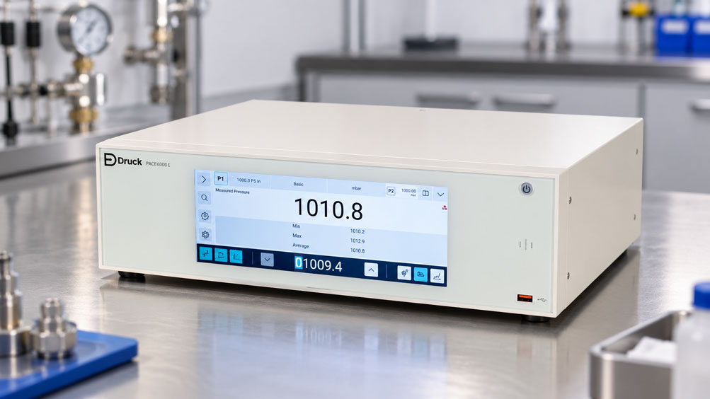
Druck PACE6000E
The Druck PACE6000E extends the modular concept to two pressure channels.
This makes it possible to implement, for example:
- two independent pressure ranges,
- auto-ranging configurations,
- more complex automated test benches
.
The Control Modules contain the pressure-related components such as sensors, valves and manifolds.
Particularly with such high-precision control components, a suitable gas supply is an important part of the overall system.
Further information can be found for the Druck PACE6000E dual-channel pressure controller.
PACE CM3 for the highest accuracy requirements
For particularly demanding calibration tasks, the PACE CM3 is available within the PACE series as a high-precision control and reference module.
The lower the required measurement uncertainty, the more important it becomes to consider more than just reference accuracy.
The following must also be appropriate for the measurement task:
- pressure stability,
- supply,
- temperature,
- test volume,
- stabilization time
.
Further information can be found for the PACE CM3 Control Module.
Further pressure controllers, hand pumps, reference instruments and calibration solutions can be found under calibration equipment at ICS Schneider.
Conclusion
Both nitrogen and appropriately treated compressed air can be very suitable for pneumatic calibration.
In calibration laboratories in particular, nitrogen offers the advantage of a clean, dry and easily defined supply.
For regular gas consumption, however, a professionally treated central compressed-air supply may be more economical.
The decisive factor is not the type of gas alone, but its quality at the actual connection of the pressure controller.
Water, oil and particles can impair precision control valves and reduce the stability and service life of the calibration system over time.
Correct sizing of the supply is equally important. Pressure regulators, filters and lines must allow sufficient gas flow, and the controller requires enough pressure reserve above the maximum required test pressure.
Thermal equalization processes must also be considered after every pressure change. A pressure value should only be recorded once the controller, gas volume and device under test have stabilized sufficiently.
For reproducible pneumatic calibrations, therefore: use clean, dry gas approved for the instrument, consistently avoid oil and particles, adequately size supply pressure and flow, allow thermal stabilization, and clearly document the gas source and test conditions.
FAQ: Pneumatic calibration with nitrogen or compressed air
Is nitrogen better than compressed air for pressure calibration?
Not inherently in terms of pressure accuracy. However, nitrogen often provides a particularly clean, dry and defined gas supply. Appropriately treated dry and oil-free compressed air can also be very suitable.
Why is nitrogen frequently recommended for precision pressure controllers?
Suitable cylinder nitrogen typically has a low moisture and contamination level. This makes it comparatively easy to establish a clean and reproducible pneumatic supply.
Can normal workshop compressed air be used?
Only if its quality meets the requirements of the pressure controller being used. Unknown residual moisture, oil content or particles mean that an existing plant compressed-air supply is not automatically suitable as a calibration medium.
Why must oil not enter a pressure controller?
Oil can deposit on control valves and sealing surfaces, alter their behaviour and also contaminate connected devices under test.
Why are particles problematic?
Small particles can impair valve seats, nozzles and pneumatic flow passages. Possible consequences include leakage, slow pressure control and pressure instability.
Why must compressed air be dry?
Moisture can condense under unfavourable pressure and temperature conditions. Liquid water can damage pneumatic components, promote corrosion and affect control performance.
What does pressure dew point mean?
The pressure dew point describes the temperature at which moisture contained in the compressed gas begins to condense under the specified pressure conditions. A lower pressure dew point means a drier gas.
How high must the supply pressure of a pressure controller be?
It must be higher than the maximum required output pressure and provide the control reserve specified by the manufacturer. For the PACE series, for example, a supply approximately 10% above the maximum required output pressure is intended.
Why is high supply pressure alone not sufficient?
The controller also requires sufficient gas flow. Lines, pressure regulators, filters or couplings that are too restrictive can cause the supply pressure to drop during a pressure step.
Why does the pressure continue to change after a rapid pressure step?
During compression or expansion, the gas temperature changes. As the gas, device under test and lines subsequently reach thermal equilibrium, the pressure can continue to change.
How long must a calibration point stabilize?
There is no universal time for all applications. Stabilization must be appropriate for the required test accuracy, device-under-test volume, pressure range and thermal behaviour of the system.
Can a contaminated device under test damage the pressure controller?
Yes. Residual oil, water or process medium in the pressure connection may be transported back into the pneumatic calibration system. Contaminated devices under test should therefore be assessed before connection.
Which pressure controller is suitable for automatic pneumatic calibrations?
Specific examples are the Druck PACE5000E for single-channel applications and the PACE6000E for dual-channel, auto-ranging and more complex test applications.
Which gases are intended for the PACE5000E and PACE6000E?
The instruments are designed for clean and dry pneumatic media such as dry air or nitrogen. The relevant instrument specification and permissible pressure ranges must be taken into account when designing the system.