


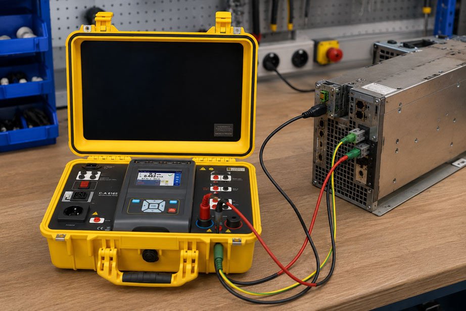
An electrical device is tested as part of a periodic inspection.
The protective conductor resistance is normal, and the visual inspection does not reveal any defects.
However, the next test step raises the question:
Protective conductor current, differential current or touch current?
All three measured quantities are related to unwanted or design-related currents outside the actual useful current path.
However, they do not describe the same thing.
Using the wrong measurement method can therefore result in:
- non-comparable measured values,
- incorrect assessment of a device under test,
- undetected leakage paths,
- unnecessary troubleshooting
.
It is particularly important to distinguish between:
protective conductor current
differential current
touch current
The protective conductor current describes the current that flows through the protective conductor while the device is operating.
The differential current, on the other hand, is determined from the current balance of the active conductors.
Touch current considers another possible current path:
accessible conductive part → human body or measuring network → earth
The appropriate measurement method should therefore not be selected solely on the basis of the available test instrument, but according to protection class, device design, possible leakage paths, operating condition and the test requirements applicable to the device under test.
Electrical test equipment can be found at ICS Schneider under Electrical Measurement and Test Equipment. Equipment for testing electrical appliances can also be found under VDE Test Equipment.
Table of Contents
- Why leakage currents occur in the first place
- Current standards framework for equipment testing
- Distinguishing protection classes I and II
- What is protective conductor current?
- What is differential current?
- What is touch current?
- Direct comparison of the three measured quantities
- Why mains filters can generate measurable leakage current
- Correctly understanding direct protective conductor current measurement
- Using the differential current method correctly
- Why touch current is measured through a measuring network
- Consider the operating condition of the device under test
- Consider mains plug orientation and polarity
- Consider parallel paths through data cables and enclosures
- Substitute leakage current as an alternative test method
- Typical testing of protection class I devices
- Typical testing of protection class II devices
- Permanently connected devices and three-phase loads
- Correctly interpreting measured values
- Consider trends instead of only pass/fail
- Typical errors in leakage current measurements
- Systematic procedure for selecting the measurement method
- Practical example: protection class I device with mains filter
- Suitable ICS products
- Conclusion
- FAQ
Why leakage currents occur in the first place
In an idealized electrical load, the entire current would flow through the intended active conductors.
For a single-phase device, for example:
L → load → N
In real electrical devices, however, additional current paths exist.
These may be caused by:
- capacitances between active conductors and the enclosure,
- EMC filters,
- interference suppression capacitors,
- cable capacitances,
- transformers,
- switch-mode power supplies,
- moisture,
- contamination,
- damaged insulation.
Not every leakage current indicates a defect
An important point:
A measurable leakage current does not automatically mean that there is an insulation fault.
In electronic devices, for example, EMC filters can cause design-related currents to flow to:
PE
or to another reference potential.
The decisive factors are therefore:
- which current path exists,
- how high the current is,
- which measurement method was used,
- which limits or manufacturer requirements apply to the device under test.
Current standards framework for equipment testing
The formerly frequently referenced combined standard:
DIN VDE 0701-0702
has since been divided into two areas of application.
Testing after repair
For the general verification of the effectiveness of protective measures of electrical equipment after repair:
DIN EN 50678 (VDE 0701)
is relevant.
Periodic testing
For periodic testing of electrical equipment:
DIN EN 50699 (VDE 0702)
is relevant.
Product-specific requirements may take precedence
Not every electrical device is tested exclusively according to these general procedures.
Specific test requirements exist for certain product groups.
Examples may include:
- medical electrical equipment,
- welding equipment,
- machinery,
- certain electrical installations,
- equipment for special applications.
Limits and test methods should therefore not be transferred indiscriminately from a general table to any arbitrary device under test.
Distinguishing protection classes I and II
The protection class has a significant influence on which current paths can exist at all.
Protection class I
In protection class I devices, accessible conductive parts that could become live in the event of a fault are connected to a protective conductor.
Typical current path:
active conductors → filter / parasitic capacitance / insulation → enclosure → PE
Protective conductor current is an important measured quantity here.
Protection class II
Protection class II devices use double or reinforced insulation and normally do not have a protective conductor connection for protection against electric shock.
A conventional protective conductor current measurement is therefore not possible.
Instead, the current between:
accessible conductive part → measuring network → earth
may be relevant.
Touch current can also be relevant for protection class I
Not every accessible conductive part of a protection class I device must necessarily be connected to the protective conductor.
For such parts, a touch current measurement may also be required.
What is protective conductor current?
Protective conductor current is the current that flows through the protective conductor of an electrical device while it is operating.
In simplified form:
device → PE conductor → earth
Typical cause
In an intact electronic device, part of this current may, for example, be caused by interference suppression capacitors.
A simplified model:
L → Y capacitor → PE
Other possible causes
- deterioration of insulation,
- moisture,
- contamination,
- damaged heating elements,
- damaged cables,
- defective filter components.
Measurement under operating conditions
In a direct protective conductor current measurement, the current actually flowing through the protective conductor is measured while the device is operating.
This gives the method an important advantage:
The device under test is in a real operating condition.
What is differential current?
With differential current measurement, the current in the protective conductor alone is not measured directly.
Instead, the current balance of all active conductors is considered.
Single-phase basic principle
Ideally:
IL = IN
or, as a vector sum of currents:
ΣIactive conductors = 0
When current flows through another path
For example:
L → device → PE
this portion of the current does not return via the neutral conductor.
A difference therefore arises between the currents in the active conductors.
Principle
In simplified form:
Idifferential = current that does not return through the jointly measured active conductors
Advantage of the differential current method
The protective conductor can remain connected during measurement.
This is particularly useful for:
- operational devices,
- larger loads,
- permanently connected equipment,
- measurements using a suitable differential current clamp.
Differential current and protective conductor current are not automatically identical
In a simple device without additional conductive connections, both values may be very similar.
However, if the device under test has additional leakage paths, differences may occur.
What is touch current?
Touch current describes a current that could flow through a person to earth when touching an accessible conductive part.
The test instrument replaces the person
During the measurement, a person is of course not used as the current path.
Instead, a defined:
measuring network
is connected between the accessible part and a reference potential.
Typical application
Touch current measurement is particularly relevant for:
- protection class II devices,
- accessible conductive parts without a PE connection,
- certain isolated connections,
- devices for which the applicable test specification requires such a measurement.
Example
A device has an accessible metal part that is not connected to PE by design.
A test lead is connected between:
metal part → measuring network → reference potential
.
The test instrument determines the relevant touch current from this.
Direct comparison of the three measured quantities
| Measured quantity | What is measured? | Typical application |
|---|---|---|
| Protective conductor current | Current actually flowing through the protective conductor of the device under test | Primarily protection class I devices |
| Differential current | Current balance or vector difference of the active conductors | Operational measurement on devices with PE and suitable test setups |
| Touch current | Current from an accessible conductive part through a defined measuring network | Protection class II and accessible conductive parts without a protective conductor connection |
Common objective – different perspectives
All methods help detect unwanted or safety-relevant current paths.
However, they consider these current paths at different points.
Why mains filters can generate measurable leakage current
Modern electrical devices often contain EMC filters.
These are intended to reduce high-frequency interference.
Typical filter structure
Among other things, safety capacitors may be present between:
L → PE
and:
N → PE
.
Capacitive current
With AC voltage, current flows through a capacitance.
In simplified form, it depends on:
- capacitance,
- frequency,
- voltage
.
Consequence
An intact device can therefore have a measurable protective conductor or differential current.
This is particularly relevant for:
- switch-mode power supplies,
- frequency converters,
- industrial PCs,
- IT equipment,
- power filters.
Multiple devices can add up
If many devices with such filters are operated together, their individual leakage currents can add up in the protective conductor system.
Correctly understanding direct protective conductor current measurement
In direct measurement, the current in the protective conductor path is measured.
Advantage
The exact electrical quantity measured is:
IPE
flowing through this protective conductor.
Disadvantage
The method requires a suitable test setup.
During the test, the device under test is energized with operating voltage.
Safety aspect
A leakage current measurement under mains voltage must therefore only be performed using:
- suitable test equipment,
- a correct test setup,
- appropriate protective measures
.
Using the differential current method correctly
The differential current method simultaneously considers all active conductors.
Single-phase
For example:
L + N
are measured together by a common summation current transformer.
Three-phase
Depending on the system:
L1 + L2 + L3 + N where applicable
must be measured together.
The protective conductor must not be included in the summation measurement
If the protective conductor were also routed through the same summation current transformer, the differential current being sought could be compensated again.
Suitable for larger loads
Using a suitable current transformer or differential current clamp, this method can be particularly useful for larger or permanently connected devices under test.
Why touch current is measured through a measuring network
The current through a person does not depend solely on a simple ohmic load.
In particular, the frequency of the current is important.
Therefore a defined measuring network is used
For touch current measurement, a standardized electrical network is used.
It reproduces the relevant electrical effect of a possible touch path for the respective test.
Weighted and unweighted measured values
Depending on the test instrument and test specification, different measuring networks or weighting methods may be specified.
Measured values obtained using different measurement methods should therefore not be compared without checking their basis.
Consider the operating condition of the device under test
Leakage currents can depend strongly on the current operating condition of the device.
Examples
A device may contain:
- a heater,
- a motor,
- a switch-mode power supply,
- relays,
- an electronic power stage.
In standby, only a small part of the circuitry may be active.
During normal operation, additional components are activated.
Measurement only in the wrong operating condition
If the device is merely switched on but not placed in the operating condition relevant to the test, a fault path may remain undetected.
Heater example
A heating element with developing insulation deterioration may only become noticeable when:
heater ON
.
Therefore
The relevant:
- switch positions,
- operating modes,
- load conditions
must be considered during testing.
Consider mains plug orientation and polarity
For devices without a clearly defined assignment of line and neutral conductors, plug orientation can influence the measured leakage current.
Why?
Internal switches, filters or single-pole switching elements may be positioned differently relative to earth depending on the mains connection.
Test instruments may therefore provide polarity reversal
With suitable test instruments, the assignment:
L ↔ N
can be reversed during the test sequence.
Which test positions are required depends on the applicable test specification and the device design.
Consider parallel paths through data cables and enclosures
In addition to the mains connection, a device under test may have further conductive connections.
Examples:
- Ethernet cable,
- USB connection,
- antenna cable,
- sensor cables,
- metal pipe,
- machine frame,
- shield connections.
This creates additional current paths
A leakage current can split across several connections.
Consequence for the measurement
A pure protective conductor current measurement in the mains cable can then produce a different value from a differential current measurement of the active supply conductors.
Example
Part of the leakage current flows through:
PE of the mains cable
and another part through:
shielded data cable → another earthed device
Document the test setup
For reproducible testing, it should therefore be clearly defined which external connections are:
- connected,
- disconnected
during measurement.
Substitute leakage current as an alternative test method
In addition to protective conductor, differential and touch current measurement, there is also:
substitute leakage current measurement
Basic principle
In this method, the device under test is not measured in exactly the same way as in normal mains operation.
Instead, an alternative measurement method is performed using a defined test voltage.
Advantage
The method can be performed without the device under test being in its normal operating state.
Limitation
Electronic or mechanical switching elements may be in different states when de-energized than during actual operation.
As a result, not all current paths may be detected.
Therefore not freely interchangeable
Substitute leakage current, differential current and direct leakage current measurement are different test methods and must not be interchanged solely according to personal preference.
Typical testing of protection class I devices
In a protection class I device, the enclosure or relevant accessible conductive parts are connected to the protective conductor.
Typical test sequence
Depending on the test specification, the following may be performed:
- visual inspection,
- protective conductor test,
- insulation test,
- leakage current test,
- functional test.
For the leakage current test
depending on the test method, the following may be relevant:
- protective conductor current,
- differential current,
- substitute leakage current
.
Accessible unearthed parts
If additional accessible conductive parts without protective conductor connection are present, they may also need to be assessed separately with regard to touch current.
Typical testing of protection class II devices
A protection class II device does not use a protective conductor as its normal protective path.
Therefore there is no
conventional measurement of:
protective conductor current in PE
Instead, the following may be relevant
- insulation resistance,
- touch current,
- substitute leakage current where applicable,
- visual and functional testing.
Measurement point
For touch current measurement, the relevant:
accessible conductive part
must actually be contacted.
If the probe is placed on an electrically insulated point, the result may be misleading.
Permanently connected devices and three-phase loads
Not every device under test has a protective contact plug.
For:
- machines,
- larger heating devices,
- pumps,
- three-phase loads,
- permanently connected electrical equipment
a conventional appliance tester using its internal test socket is not always the appropriate solution.
Differential current clamp
For suitable test methods, a sensitive current clamp can be used.
All active conductors must be routed together through the clamp.
Three-phase example
L1 + L2 + L3 + N
are measured together.
The protective conductor:
PE
is not included.
Important
The current clamp must be suitable for the required:
- sensitivity,
- frequency bandwidth,
- measurement task
.
Correctly interpreting measured values
The measured value alone does not answer the question:
device safe or unsafe?
Assessment must include
- the applied standard or test specification,
- device type,
- protection class,
- measurement method,
- operating condition,
- manufacturer information,
- measurement uncertainty.
Do not use a universal limit value
Different device types and test methods may have different limits.
A single value found on the internet should therefore not be applied to an arbitrary device under test without verification.
Consider trends instead of only pass/fail
For periodic tests, it is not only the current limit value that is of interest.
Example
A device produces the following values over several inspections:
| Inspection | Leakage current |
|---|---|
| Year 1 | 0.28 mA |
| Year 2 | 0.31 mA |
| Year 3 | 0.34 mA |
| Year 4 | 0.71 mA |
The final value may deserve additional attention
Even if a measured value is still within the permissible range for the application, a significant change compared with previous inspections can indicate:
- moisture,
- contamination,
- aging,
- developing insulation damage
.
The measurement method must remain comparable
A trend analysis is only meaningful if the following remain as consistent as possible:
- measurement method,
- operating condition,
- connection condition,
- test instrument or measurement conditions.
Typical errors in leakage current measurements
| Observation | Possible cause | Recommended check |
|---|---|---|
| Protective conductor current significantly higher than in the previous inspection | Insulation deterioration, moisture or changed filter condition | Check trend, insulation measurement and operating condition |
| Differential current and protective conductor current differ significantly | Additional parallel leakage path | Check data, shield and enclosure connections |
| Touch current practically zero | Incorrect measurement point or accessible part electrically insulated | Check measurement point and contact |
| Measured value changes with a different plug orientation | Internal filter or switching structure | Perform the specified polarity tests |
| Device passes substitute leakage current test but shows high current during operation | Current path is only activated in the operating state | Check direct or differential current measurement |
| Leakage current rises when the heater is switched on | Heating element or its insulation is abnormal | Compare cold/warm measurement and insulation condition |
| Measured value fluctuates during operation | Different operating conditions or electronic load control | Observe the operating cycle and document the measurement condition |
| Differential current clamp unexpectedly shows zero | PE was accidentally routed through the clamp as well | Check conductor routing |
| Differential current clamp shows an unrealistically high value | Not all active conductors were measured together | Measure L, N or all phases together |
| Measured values from two inspections are not comparable | Different measurement methods were used | Compare test reports and measurement methods |
| Device with mains filter shows leakage current despite intact insulation | Design-related capacitive current through the filter | Consider manufacturer information and overall assessment |
Systematic procedure for selecting the measurement method
- Determine the reason for testing: Distinguish between testing after repair, periodic testing and product-specific testing.
- Determine the applicable test specification: Consider general and, where applicable, product-specific standards.
- Determine the protection class: Identify protection class I, II or a special protective concept.
- Check the protective conductor connection: Identify relevant PE connections for protection class I.
- Identify accessible conductive parts: Include unearthed metal parts as well.
- Document additional connections: Consider data cables, shields and other earth paths.
- Select the appropriate leakage current method: Determine whether protective conductor, differential, touch or an approved substitute method is required.
- Configure the test instrument appropriately: Select measuring network, measurement range and test sequence.
- Connect the device under test safely: Ensure correct mains and protective conductor connection.
- Activate relevant operating conditions: Consider motors, heaters and other switching states.
- Reverse polarity where required: If specified for the device under test and the test method.
- Record a stable measured value: Distinguish short-term switch-on events from steady-state operating values.
- Test additional accessible parts: Place the probe on the actually accessible conductive parts.
- Compare the result with the permissible value: Use the applicable standard and manufacturer information.
- Compare previous values: Detect abnormal trends during periodic testing.
- Document the measurement method: Save not only the numerical value but also the method used.
- Assess the test result: Consider visual inspection, protective conductor, insulation, leakage current and functional test together.
Practical example: protection class I device with mains filter
An industrial electronic device has:
- a 230 V mains connection,
- a metal enclosure,
- a protective conductor connection,
- an internal switch-mode power supply,
- an EMC mains filter.
Step 1: Determine the protection class
The conductive enclosure is connected to PE.
For the area under consideration, this is therefore a device with a protective conductor.
Step 2: Check the protective conductor connection
Before leakage current measurement, the protective conductor connection is tested.
It is low-resistance and normal.
Step 3: Switch on the device
The device is put into operation under the safe conditions specified for the test.
Step 4: Measure protective conductor current
The test instrument measures a reproducible protective conductor current.
Because the device contains an EMC filter, a non-zero measured value does not automatically indicate a defect.
Step 5: Measure differential current
The differential current is then determined.
Both values are close to each other.
This indicates that most of the leakage current returns through:
PE
.
Step 6: Connect an additional data cable
A shielded communication cable is now connected to another earthed device.
The protective conductor current in the mains cable changes slightly.
The differential current changes more significantly.
Cause
Part of the current now also follows the path:
device enclosure → cable shield → second device → earth
Finding
The two measurement methods are not “better” or “worse”.
They observe different points in the current paths.
Step 7: Documentation
The test report therefore records:
- measurement method,
- operating condition,
- connected auxiliary cables,
- measured value,
- assessment.
Result
Only knowledge of the measurement principle turns a leakage current value into technically useful information.
Suitable ICS products for leakage current and equipment testing
C.A 6165 – Multifunction Tester
A particularly suitable device from the ICS portfolio is the:
C.A 6165 multifunction tester
ICS explicitly lists the following functions for the device:
- substitute leakage current measurement,
- protective conductor current measurement,
- differential leakage current measurement,
- touch current measurement.
Additional test functions
The C.A 6165 also provides, among other things:
- continuity testing at 200 mA, 4 A, 10 A and 25 A,
- insulation resistance measurement with different test voltages up to 1,000 V,
- AC and DC dielectric withstand testing,
- discharge time measurement,
- functional testing,
- power measurement,
- automatic test sequences.
Why the C.A 6165 is particularly well suited to this topic
For this article, the decisive point is that several leakage current methods are available in one instrument.
Depending on the test task, the user can therefore distinguish between:
protective conductor current
differential current
touch current
and:
substitute leakage current
.
Further information can be found under C.A 6165 Multifunction Tester at ICS Schneider.
CA 6163 – Multitester / Machine Tester
Another solution listed by ICS is the:
CA 6163 Multitester / Machine Tester
ICS specifies, among other things:
- direct leakage current measurement,
- differential leakage current measurement,
- substitute leakage current measurement,
- touch leakage current measurement,
- weighted and unweighted measuring networks.
Additional functions include automatic test sequences, continuity, insulation and dielectric strength testing as well as extensive documentation options.
Further information can be found under CA 6163 Multitester / Machine Tester at ICS Schneider.
Which ICS device is suitable?
| Application | Suitable ICS solution |
|---|---|
| Protective conductor, differential, touch and substitute leakage current with one instrument | C.A 6165 |
| Comprehensive electrical safety testing with several leakage current methods | CA 6163 |
| Automated test sequences and test reports | C.A 6165 or CA 6163 |
| Testing electrical equipment, machines and switchboards | C.A 6165, depending on the specific test specification |
Further devices can be found under Equipment Testing at ICS Schneider.
Conclusion
Protective conductor current, differential current and touch current all belong to the field of electrical safety, but they describe different measured quantities.
The:
protective conductor current
is the current actually flowing through the protective conductor.
The:
differential current
results from the current balance of the active conductors and detects the portion of current returning through other paths.
The:
touch current
considers the possible current from an accessible conductive part through a defined measuring network to earth.
This results in different typical areas of application.
For protection class I devices:
- protective conductor current,
- differential current
are often the main focus.
For protection class II devices or unearthed accessible metal parts, however:
touch current
is particularly relevant.
In addition, depending on the test specification and device:
substitute leakage current
may be specified as an alternative test method.
Particular attention is required for modern electronic devices.
EMC filters can generate design-related leakage currents even when the insulation is completely intact.
The following can also affect the measured value:
- operating condition,
- mains polarity,
- external data cables,
- cable shields,
- additional earth connections
.
A single numerical value without specifying the measurement method therefore has only limited meaning.
For practical applications:
Determine the reason for testing → clarify the applicable test specification → determine the protection class → identify accessible conductive parts → identify additional earth paths → select the appropriate leakage current method → configure the test instrument correctly → establish the relevant operating condition → consider polarity where applicable → measure protective conductor, differential or touch current → assess the measured value against the limit applicable to the application → compare previous values → document measurement method and operating condition in the test report.
FAQ: Protective Conductor Current, Differential Current and Touch Current
What is protective conductor current?
Protective conductor current is the current that flows through the protective conductor of a device while it is operating.
What is differential current?
Differential current results from the vector sum of the currents in the active conductors. If part of the current returns via another path, a measurable difference occurs.
What is touch current?
Touch current is the current that could flow from an accessible conductive part through a possible touch path to earth. During testing, this path is reproduced using a defined measuring network.
Are protective conductor current and differential current the same?
No. In simple circuits, the values may be similar, but the measurement methods observe different current paths.
When is protective conductor current measured?
Typically for protection class I devices when the actual current through the protective conductor is to be determined under operating conditions.
When is differential current measured?
The differential current method is suitable, among other things, for operational tests in which the sum of all active conductors can be measured together.
When is touch current measured?
Particularly for protection class II devices and accessible conductive parts that are not connected to the protective conductor.
Does a protection class II device have protective conductor current?
Under the normal protective concept, a protection class II device does not have a protective conductor and therefore does not have protective conductor current in the conventional sense.
Can touch current also be measured on a protection class I device?
Yes. If accessible conductive parts are present that are not connected to PE, a corresponding test may be required.
Why do intact devices have leakage current at all?
Among other things, mains filters, interference suppression capacitors and parasitic capacitances can cause current to flow to earth or PE even in a fault-free device.
Is every leakage current a fault?
No. The decisive factors are the magnitude, measurement method, device type and the requirements applicable to the device under test.
Why do switch-mode power supplies often have leakage current?
EMC filters often contain capacitive coupling between the mains side and the protective conductor or other reference potentials.
Can the leakage currents of several devices add up?
Yes. If several devices are operated together, their design-related leakage currents can add up in the protective conductor system.
Why must the device be switched on during a leakage current measurement?
Direct operating-current methods are intended to detect the real current paths of the energized device.
Does every operating mode have to be tested?
The relevant operating conditions must be considered in accordance with the applicable test specification. A fault path may, for example, only become active when a heater is switched on or a motor is running.
Can plug orientation affect the leakage current?
For certain devices, yes. Internal filter and switching structures can produce different measured values depending on the assignment of line and neutral.
What is a differential current clamp?
A sensitive current clamp that measures all active conductors of a circuit together. The remaining summation current corresponds to the current flowing through other paths.
Must the protective conductor be routed through the differential current clamp?
No. For conventional differential current measurement, the active conductors are measured together, not the protective conductor.
Which conductors must be routed through the differential current clamp in a three-phase system?
All current-carrying active conductors of the circuit under consideration, typically L1, L2, L3 and – if present and relevant – N.
Why can data cables influence leakage current measurement?
Shielded or earthed data cables can create additional current paths between the device under test and other earthed devices.
What is substitute leakage current?
Substitute leakage current is determined using an alternative test method in which the device under test does not have to be operated under normal mains conditions.
Is substitute leakage current the same as protective conductor current?
No. They are different measurement methods.
Can a substitute leakage current measurement miss an operating fault?
This is possible if a relevant current path is only activated by a relay, electronic switch or specific operating condition.
Why is a measuring network used for touch current?
So that the electrical touch path can be reproducibly simulated and evaluated in accordance with the applicable test specification.
What does weighted touch current mean?
The measured quantity is evaluated using a defined frequency-dependent measuring network. The exact implementation depends on the applicable test specification.
Which standard applies after a repair?
For general electrical equipment in Germany, DIN EN 50678 (VDE 0701) is the corresponding general standard for verification after repair. Product-specific requirements must also be considered.
Which standard applies to periodic testing?
For general periodic testing of electrical equipment, DIN EN 50699 (VDE 0702) is relevant, provided that no other product-specific regulation takes precedence.
Does the combined DIN VDE 0701-0702 still exist?
The former combined standard has been split for current test procedures into DIN EN 50678 (VDE 0701) and DIN EN 50699 (VDE 0702).
Can I use one universal limit for every leakage current?
No. The permissible value depends, among other things, on device type, measurement method and the applicable test specification.
Why should the measurement method be stated in the test report?
Because protective conductor, differential, touch and substitute leakage current do not represent exactly the same measured quantity. Without specifying the method, later comparisons are only of limited value.
Why are previous values useful during periodic testing?
A significant increase compared with earlier measurements can indicate aging, moisture, contamination or developing insulation problems.
Which ICS device measures protective conductor current, differential current and touch current?
The C.A 6165 is explicitly listed by ICS with protective conductor current, differential leakage current, touch current and substitute leakage current measurement.
What is the C.A 6165?
The C.A 6165 is a multifunction tester for electrical safety testing of electrical equipment, machines and switchboards.
Which additional tests can the C.A 6165 perform?
ICS lists, among other things, continuity testing, insulation resistance measurement, dielectric withstand testing, discharge time measurement and functional testing.
What is the CA 6163?
The CA 6163 is a multitester or machine tester listed by ICS with direct, differential, substitute and touch leakage current measurements.
Where can I find the C.A 6165 at ICS Schneider?
Further information can be found under C.A 6165 Multifunction Tester at ICS Schneider.
Where can I find the CA 6163 at ICS Schneider?
Further information can be found under CA 6163 Multitester / Machine Tester at ICS Schneider.
Where can I find additional VDE test equipment at ICS Schneider?
An overview can be found under VDE Test Equipment at ICS Schneider.