


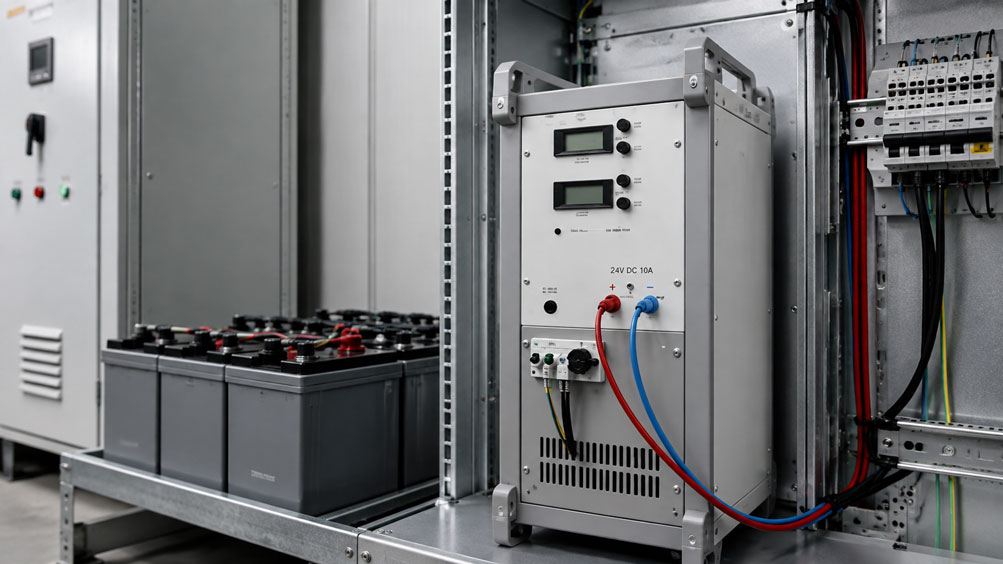
The laboratory power supply is set to:
24.0 V DC
.
The connected device under test requires under load:
30 A
.
The voltage directly at the output terminals of the power supply is correct.
However, only:
22.9 V
is measured at the load located several meters away.
If the load current is reduced, the voltage at the load rises again.
This does not necessarily mean that the power supply is defective.
The cause is often found in the electrical connection between the power supply and the load.
Every cable, terminal, connector, fuse and switching contact has an electrical resistance. At high DC currents, even a small total resistance can cause a significant voltage drop and high power loss.
The fundamental relationship is:
ΔU = I · R
and for the power loss:
Ploss = I² · R
The second relationship in particular is critical for high-current power supplies.
If the current doubles while the resistance remains the same, the voltage drop also doubles – but the power loss increases by a factor of four.
With laboratory power supplies providing output currents of:
- 20 A,
- 30 A,
- 40 A,
- 60 A
a wiring arrangement that works perfectly at lower currents can therefore quickly become unsuitable.
A specific example from the ICS portfolio is the:
2257.1 high-power DC voltage regulator
with:
0 … 30 V DC / 0 … 40 A / 1,200 W
With a possible output current of up to 40 A, cable cross-section, contact resistances, protection and thermal loading become essential elements of the complete power supply system.
The quality of a DC power supply therefore does not end at the output terminals of the power supply. What matters is the voltage that actually reaches the load under real operating conditions.
Power supplies and laboratory power supplies can be found at ICS Schneider under Power Supplies / Laboratory Power Supplies. Further products can be found under Power Supply.
Table of Contents
- Why the voltage at the load can be lower
- Calculate voltage drop using Ohm’s law
- Consider supply and return conductors together
- Influence of cable cross-section
- Why high currents are particularly critical
- Calculate power loss and heating
- Do not underestimate contact resistances
- Select connectors correctly for high DC currents
- Consider fuses and fuse holders
- Understand CV operation correctly
- Understand CC operation and current limiting correctly
- Distinguish between voltage drop and current limiting
- Consider dynamic loads and inrush currents
- Measure voltage directly at the load
- Four-wire measurement for diagnosing contact resistances
- Supply multiple loads correctly
- Correctly size long DC cables
- Consider temperature and cable resistance
- Typical fault patterns
- Systematic sizing procedure
- Practical example: 24 V device under test at 30 A
- Suitable ICS product
- Conclusion
- FAQ
Why the voltage at the load can be lower
An ideal electrical conductor would have:
R = 0 Ω
In reality, however, every conductor has a finite resistance.
This also applies to:
- terminals,
- connectors,
- fuses,
- relay contacts,
- switches,
- PCB traces.
The complete electrical connection between the power supply and the load can therefore be regarded in simplified form as a series resistance.
The following applies:
Upower supply = Uload + ΔU
or:
Uload = Upower supply − ΔU
No significant voltage drop without current
Under no-load conditions, almost no load current flows.
Therefore, approximately:
ΔU ≈ 0 V
This is why a power supply may appear completely normal under no-load conditions.
Only under higher load does it become apparent that:
Uload < Upower supply
Typical diagnostic indication
If the voltage difference between the power supply and the load increases as the load current rises, the current-carrying connection should be checked first.
Calculate voltage drop using Ohm’s law
For an ohmic resistance:
ΔU = I · R
where:
ΔU= voltage drop in V,I= current in A,R= resistance in Ω.
Example
The total resistance of a connection path is:
0.04 Ω
At:
5 A
the voltage drop is:
ΔU = 5 A · 0.04 Ω = 0.20 V
At:
20 A
this becomes:
ΔU = 20 A · 0.04 Ω = 0.80 V
and at:
40 A
already:
ΔU = 40 A · 0.04 Ω = 1.60 V
Relative error
With a 24 V supply, 1.6 V corresponds to approximately:
6.7 %
of the nominal voltage.
This can already make a significant difference for sensitive devices under test.
Consider supply and return conductors together
A common calculation error is to use only the physical distance between the power supply and the load.
In a DC connection, however, the current flows via:
positive conductor → load → negative conductor
back to the source.
Example
Distance between power supply and load:
5 m
With equal supply and return conductor lengths, the total current-carrying conductor length is:
5 m + 5 m = 10 m
Conductor resistance
In simplified form:
R = ρ · l / A
where:
ρ= resistivity of the conductor material,l= total conductor length,A= conductor cross-section.
Influence of cable cross-section
The conductor resistance is inversely proportional to the conductor cross-section.
This means:
larger cross-section → lower resistance → lower voltage drop
Example with the same cable length
A larger copper conductor cross-section reduces:
- voltage drop,
- power loss,
- heating.
Do not select the cable cross-section based solely on current-carrying capacity
A cable may be thermally capable of carrying a certain current and still produce too much voltage drop for a precise low-voltage supply.
For test systems, at least two conditions should therefore be checked separately:
- Is the cable thermally suitable for the current?
- Is the resulting voltage drop acceptable for the application?
Especially at low DC voltages, the permissible voltage drop is often the more restrictive sizing criterion.
Why high currents are particularly critical
For voltage drop:
ΔU ∝ I
For power loss, however:
Ploss ∝ I²
Example
Total resistance:
R = 0.03 Ω
| Current | Voltage drop | Power loss |
|---|---|---|
| 5 A | 0.15 V | 0.75 W |
| 10 A | 0.30 V | 3.0 W |
| 20 A | 0.60 V | 12.0 W |
| 40 A | 1.20 V | 48.0 W |
From 10 A to 40 A, the current has increased by a factor of four.
The power loss increases from:
3 W
to:
48 W
and therefore by a factor of:
16
Consequence
In high-current test systems, small resistances are not automatically insignificant.
Calculate power loss and heating
Electrical power loss is converted into heat.
The following applies:
Ploss = I² · R
It is not only cables that heat up
Power loss can also occur locally in:
- a connector,
- a screw terminal,
- a fuse holder,
- a relay contact
.
Local resistances are particularly critical
A long conductor distributes its power loss over several meters.
A high contact resistance in a single terminal, on the other hand, dissipates the power loss over a very small area.
This can result in significantly higher local temperatures.
Heat accelerates further deterioration
Depending on the contact, elevated temperatures can in turn:
- accelerate oxidation,
- stress plastics,
- reduce spring forces,
- further increase contact resistance.
This can create a self-reinforcing fault mechanism.
Do not underestimate contact resistances
A test setup does not normally consist of one continuous copper cable.
There are typically several transition points between the power supply and the device under test.
Example
Power supply → terminal → cable → fuse → relay → connector → device under test
Every transition contributes to the total resistance
In simplified form:
Rtotal = Rcable + Rterminal + Rfuse + Rrelay + Rconnector + ...
Even milliohms become significant at high currents
An additional contact resistance of:
10 mΩ = 0.010 Ω
at:
40 A
already causes:
ΔU = 40 A · 0.010 Ω = 0.40 V
and a power loss of:
P = 40² · 0.010 = 16 W
at this resistance point.
At 40 A, a single poor contact can therefore be responsible for significant voltage loss and considerable heating.
Select connectors correctly for high DC currents
In test systems, loads are frequently connected via detachable connectors.
The connector must not only be suitable for the voltage.
The following should be checked, among other things
- permissible continuous current,
- contact resistance,
- permissible ambient temperature,
- connection cross-section,
- number of mating cycles,
- suitability for DC.
Consider aging
A connector that works perfectly when new may develop a higher contact resistance after many mating cycles.
For recurring tests, the mechanical function alone should therefore not be assessed.
Typical warning sign
If a single connector is significantly warmer than the connected cable, its contact resistance should be checked.
Consider fuses and fuse holders
A high-current supply must be appropriately protected.
However, the fuse itself also has a resistance.
The fuse holder is part of the measurement chain
During troubleshooting, the following should therefore be considered:
- fuse,
- fuse holder,
- connection points
.
Do not select a fuse based solely on nominal current
The following are also relevant:
- trip characteristic,
- inrush current,
- cable cross-section,
- possible short-circuit current,
- breaking capacity.
Understand CV operation correctly
Laboratory power supplies typically operate with voltage and current regulation.
One important operating mode is:
CV = Constant Voltage
or:
constant-voltage operation
In CV operation
the power supply attempts to keep the set output voltage constant.
Within the permissible limits, the load determines the required current.
Example
Setting:
24 V / current limit 35 A
If the load requires:
10 A
the power supply operates in CV mode.
Understand CC operation and current limiting correctly
The second important operating mode is:
CC = Constant Current
or:
constant-current operation
The current limit is reached
If the load attempts to draw more current than is set or permitted, the power supply limits the current.
The voltage then decreases as required to maintain the current limit.
Example
Power supply:
24 V
Current limit:
20 A
The load attempts to draw:
28 A
.
The power supply can then switch to CC mode.
The voltage is subsequently lower than:
24 V
Distinguish between voltage drop and current limiting
A low voltage at the device under test can have two fundamentally different causes.
Case A: Voltage drop in the connection cable
Directly at the power supply:
24.0 V
At the load:
22.8 V
The power supply continues to operate in CV mode.
In this case, the difference is most likely caused by the connection path.
Case B: Power supply is operating in current limiting mode
Directly at the power supply:
21.5 V
At the load:
20.8 V
At the same time, the power supply indicates CC operation.
In this case, it must first be determined why the current limit has been reached.
Both faults can occur simultaneously
At high currents, both:
- current limiting,
- cable losses
may occur.
Consider dynamic loads and inrush currents
Not every load draws a constant current.
Typical dynamic loads
- motor controllers,
- DC/DC converters,
- power electronics,
- heaters,
- solenoid valves,
- capacitive inputs,
- industrial PCs.
Inrush current
A device with, for example:
15 A continuous current
may briefly draw significantly more current during switch-on.
Possible consequences
- current limiting is activated,
- the voltage briefly drops,
- the device under test restarts,
- relays drop out,
- communication is reset.
A static multimeter measurement is not always sufficient
Short voltage dips can be investigated more effectively using:
- an oscilloscope,
- a fast data logger
.
Measure voltage directly at the load
For diagnosis, at least two voltages should be distinguished:
Usource
directly at the output terminals of the power supply
and:
Uload
directly at the supply terminals of the load.
Difference
ΔU = Usource − Uload
Estimate total resistance
If the load current is also known:
Rtotal = ΔU / I
Example
Measured:
Usource = 24.05 V
Uload = 23.15 V
I = 30 A
This gives:
ΔU = 0.90 V
and:
Rtotal = 0.90 V / 30 A = 0.030 Ω
or:
30 mΩ
Four-wire measurement for diagnosing contact resistances
For very small resistances, a conventional two-wire resistance measurement can become inaccurate.
The reason:
The resistance of the test leads and their contact points is included in the measurement.
Four-wire or Kelvin measurement
With four-wire measurement:
- the current path,
- the voltage measurement
are routed separately.
This allows very small resistances to be determined much more reliably.
Suitable, for example, for
- high-current cables,
- bolted connections,
- fuse holders,
- connector contacts,
- relay and contactor contacts.
This makes it possible to locate an abnormal voltage drop more precisely.
Supply multiple loads correctly
When several loads are supplied, an unfavorable daisy-chain arrangement should be avoided.
Unfavorable
Power supply → load A → load B → load C
when high currents are routed through shared cable sections.
Voltage distribution
The most distant load may then experience the highest voltage drop.
Star-shaped supply
Depending on the application, a star-shaped distribution may be useful:
Power supply → central distribution point
and from there separately to:
- load A,
- load B,
- load C.
Advantage
The voltage drops in the individual load branches influence each other less.
Correctly size long DC cables
The resistance increases proportionally with cable length.
In simplified form:
R ∝ l
Double the length
With the same cross-section:
double the cable length → approximately double the resistance → approximately double the voltage drop
Therefore consider this at an early stage
When designing a test system, the power supply should not be selected first and then connected using any convenient cable.
Instead, the following should be considered together:
- voltage,
- current,
- cable length,
- cross-section,
- connectors,
- permissible voltage drop.
Consider temperature and cable resistance
The electrical resistance of copper increases with temperature.
Consequence under high continuous load
A cable heats up.
Its resistance therefore increases.
This in turn increases:
- voltage drop,
- power loss.
Practical test at operating temperature
In high-current test systems, the voltage drop should therefore not only be checked immediately after switch-on.
A measurement after an extended period under load can provide additional information.
Typical faults in high-current laboratory power supplies
| Observation | Possible cause | Recommended check |
|---|---|---|
| Power supply shows 24 V, but only 23 V is present at the device under test | Voltage drop in cables or contacts | Measure voltage simultaneously at source and load |
| Voltage difference increases with current | Ohmic resistance of the connection path | Calculate ΔU/I |
| Power supply indicates CC instead of CV | Current limit reached | Check load current and configured current limit |
| Device under test repeatedly restarts during switch-on | Inrush current causes voltage drop or current limiting | Measure voltage profile during switch-on |
| Connector becomes noticeably warm | Excessive contact resistance or insufficient current rating | Check contact and connector |
| Fuse holder becomes hot | High contact resistance | Measure voltage drop across fuse and holder |
| Voltage is correct when cold but drops later | Heating increases cable or contact resistance | Check temperature and voltage drop at operating temperature |
| Only the most distant load has undervoltage | Unfavorable distribution or branch cable too long | Compare voltages at all load points |
| Voltage drops only briefly | Dynamic load or inrush current | Perform oscilloscope measurement |
| Voltage drop increases over several weeks | Aging or loose contact | Check terminals and connectors |
| Cable is sufficiently thick but voltage still drops significantly | Contact or fuse resistance | Measure voltage drop section by section |
Systematic sizing procedure for a high-current DC supply
- Determine the required load voltage: Document the nominal voltage and permissible voltage range of the load.
- Determine continuous current: Establish the normal operating current.
- Determine peak current: Consider inrush currents and short-term load currents.
- Size the power supply: Select a suitable voltage, current and power range.
- Consider CV/CC behavior: Set the current limit so that both the device under test and the supply path are protected.
- Determine cable length: Consider both supply and return conductors.
- Calculate conductor cross-section: Check current-carrying capacity and permissible voltage drop.
- Select connectors: Consider continuous current, contact resistance and connection cross-section.
- Size the fuse: Protect the cable and device under test appropriately.
- Consider switching contacts: Check relays and contactors for sufficient DC current-carrying capability.
- Plan the distribution: Minimize shared high-current paths when supplying multiple loads.
- Measure voltage without load: Verify basic operation.
- Increase the load gradually: Compare voltage directly at the source and at the load.
- Determine voltage drop: ΔU = Usource − Uload.
- Estimate total resistance: R = ΔU / I.
- Calculate power loss: P = I² · R.
- Check contact points: Locate abnormal voltage drops section by section.
- Observe temperatures: Check cables, terminals, fuses and connectors after extended operation under load.
- Test dynamic loads: Investigate inrush currents and load steps.
- Document the results: Record cable cross-section, cable length, current limit and measured voltages.
Practical example: 24 V device under test at 30 A
An industrial device under test is to be operated at:
24.0 V DC
.
The continuous current is:
30 A
Step 1: Voltage directly at the power supply
The measured value is:
24.02 V
Step 2: Voltage at the device under test
Under a 30 A load, only:
22.91 V
is measured at the input of the device under test.
Step 3: Voltage drop
ΔU = 24.02 V − 22.91 V
ΔU = 1.11 V
Step 4: Total resistance
R = 1.11 V / 30 A
R = 0.037 Ω
or:
37 mΩ
Step 5: Power loss
P = 30² · 0.037
P ≈ 33.3 W
The complete connection path therefore dissipates more than:
33 W
as heat.
Step 6: Section-by-section voltage measurement
The individual sections are checked:
| Section | Voltage drop at 30 A |
|---|---|
| Positive cable | 0.31 V |
| Negative cable | 0.30 V |
| Fuse + fuse holder | 0.12 V |
| Connector | 0.33 V |
| Other transitions | 0.05 V |
Step 7: Identify the abnormal connector
The connector alone causes:
0.33 V
of voltage drop.
Its effective resistance is:
R = 0.33 V / 30 A
R = 0.011 Ω
or:
11 mΩ
Step 8: Power loss at the connector
P = 30² · 0.011
P ≈ 9.9 W
Almost 10 W is therefore converted into heat in the connector contact alone.
Step 9: Improve the connection
After replacing the connector and optimizing the cable cross-section, the total voltage drop is reduced to:
0.42 V
The voltage at the device under test is now:
23.60 V
.
Step 10: Assess target voltage and application
It is then checked whether the remaining difference is acceptable for the device under test or whether the cable cross-section should be increased further.
Result
The original undervoltage was not caused by a regulation fault in the power supply. The cause was the resistance of the connection path – particularly an unsuitable or abnormal connector contact.
Suitable ICS product for high-current DC testing
2257.1 – High-power DC voltage regulator
For applications with high DC currents, ICS Schneider offers the:
2257.1 high-power DC voltage regulator
as a benchtop unit.
The most important technical data specified by ICS are:
| Feature | 2257.1 |
|---|---|
| Output voltage | 0 … 30 V DC |
| Output current | 0 … 40 A |
| Output power | 1,200 W |
| Continuous power | 1,200 W |
| Input | 230 V AC / 50 Hz |
| Input/output isolation | galvanically isolated, floating |
| CV load stability at 0–100 % load | 50 mV |
| CV ripple voltage RMS | 1 mV |
| Settling time | 30 ms |
| Operating modes | automatic CV / CC changeover |
| Protection | overtemperature protection, short-circuit proof |
| Regulation | voltage and current regulation |
| Output connection | 4 mm binding posts, screw and plug connection |
| Cooling | fan |
| Housing | benchtop unit |
Why the 2257.1 is well suited to this topic
With a maximum output current of:
40 A
the voltage drop of the external connection path becomes particularly relevant.
Even:
10 mΩ
of total resistance causes at 40 A:
0.4 V
of voltage drop.
At:
30 mΩ
it would already be:
1.2 V
CV/CC regulation
The 2257.1 provides automatic changeover between:
CV = Constant Voltage
and:
CC = Constant Current
This allows the output current to be limited and the device under test to be supplied in a controlled manner.
Do not confuse remote control with Remote Sense
For the 2257.1, ICS also specifies on request:
- remote control input,
- monitor output.
These functions must not be confused with:
Remote Sense / external voltage sensing
.
Remote Sense is not specified for the 2257.1 on the ICS product page and is therefore not part of this article.
Further variants
Within the high-power benchtop device product group, ICS offers additional DC voltage regulators with different combinations of output voltage and output current.
The selection should therefore be based on:
- required voltage,
- continuous current,
- peak current,
- power,
- regulation behavior
.
Further information can be found under 2257.1 High-Power DC Voltage Regulator at ICS Schneider.
An overview of further devices can be found under High-Power Benchtop Devices at ICS Schneider.
Conclusion
With a DC laboratory power supply, the set output voltage alone does not determine the actual supply voltage at the device under test.
Real electrical resistances exist between the power supply and the load.
The fundamental relationship is:
ΔU = I · R
At high currents, the power loss becomes particularly important:
Ploss = I² · R
This is why even a few milliohms can have a significant effect at 30 or 40 A.
The total resistance does not consist only of the cables.
The following must also be taken into account:
- terminals,
- connectors,
- fuses,
- fuse holders,
- relays,
- contactors,
- distribution points.
A voltage problem should therefore always be investigated by measuring at two points:
voltage directly at the power supply
and:
voltage directly at the load
Using the difference and the load current, the effective total resistance of the connection path can be estimated.
It must also be determined whether the power supply is:
operating in CV mode
with voltage being lost only along the cable path, or whether:
CC mode
is active and current limiting is already taking effect.
With dynamic loads, inrush currents and short voltage dips must also be considered.
For high-current applications, the 2257.1 high-power DC voltage regulator with 0 … 30 V DC, 0 … 40 A and 1,200 W listed by ICS is a practical example of why the external current path must be treated as part of the complete system design.
For practical applications:
Define load voltage → determine continuous and peak current → size the power supply → determine cable length for supply and return paths → size the cross-section according to current-carrying capacity and voltage drop → consider connectors and fuses → set CV/CC limits → measure voltage directly at source and load → determine ΔU → estimate total resistance with R = ΔU/I → assess power loss with P = I²R → locate abnormal contact points → check temperature under continuous load → test dynamic load changes → document the setup.
FAQ: Voltage Drop in DC Laboratory Power Supplies
Why is the voltage at the load lower than at the laboratory power supply?
Cables, terminals, connectors and other components have electrical resistance. When current flows, a voltage drop occurs across them.
How is voltage drop calculated?
In simplified form using ΔU = I · R.
Why does voltage drop increase at higher current?
Because voltage drop is directly proportional to current.
Why are high-current power supplies particularly critical?
In addition to voltage drop, power loss increases with the square of the current. P = I² · R applies.
What do 10 mΩ mean at 40 A?
At 10 mΩ and 40 A, the voltage drop is 0.4 V and the power loss is 16 W.
Do I have to include both supply and return conductors in the calculation?
Yes. In a two-pole DC supply, current flows through both the supply and return conductors.
Why is a load located 5 m away electrically connected by 10 m of cable?
Because with equal cable lengths, 5 m of supply conductor and 5 m of return conductor carry the current.
How can I reduce cable resistance?
Primarily by using a larger conductor cross-section, shorter cables and minimizing contact resistances.
Is it sufficient to select the cable cross-section based on current-carrying capacity?
No. Especially at low DC voltages, the permissible voltage drop should also be considered.
Can terminals cause a significant voltage drop?
Yes. Loose, oxidized or thermally damaged terminals in particular can have increased contact resistance.
Can connectors cause a voltage drop?
Yes. Contact resistance, current rating and connector aging must be considered.
Why does a poor connector contact become warm?
Its increased resistance causes power loss under load according to P = I² · R.
Can fuses cause a voltage drop?
Yes. Both the fuse itself and the fuse holder and connection points have electrical resistance.
What does CV mean on a power supply?
CV stands for Constant Voltage. The power supply maintains the output voltage at the set value as long as the current limit is not reached.
What does CC mean?
CC stands for Constant Current. Once the current limit is reached, the power supply limits the current and the output voltage may decrease.
Why does my power supply suddenly indicate CC?
The connected load is attempting to draw more current than the configured current limit permits, or the load has a very low resistance or behaves almost like a short circuit.
How do I distinguish between cable loss and current limiting?
Measure the voltage directly at the power supply and directly at the load while also checking whether the power supply is operating in CV or CC mode.
Can both occur at the same time?
Yes. The power supply can be operating in current limiting mode while additional voltage losses occur in the connection cable.
How do I determine the total resistance of the connection path?
Under a known load, R = ΔU / I can be used as an approximation.
Why should I not simply use an ohmmeter?
Very small resistances are affected by the resistance of the test leads and contact points in a conventional two-wire measurement.
What is a four-wire resistance measurement?
In a four-wire or Kelvin measurement, the current path and voltage measurement are routed separately. This allows very small resistances to be measured more accurately.
Why does the voltage only drop under high load?
Under no-load conditions, the current is very low and so is the voltage drop. The resistance of the connection path only becomes noticeable as the load increases.
Why does the voltage drop more after extended operation?
One possible cause is heating of the cables or contacts. The resistance of copper increases with temperature.
How can I identify a poor contact?
Indications include an unusually high local voltage drop, heating, discoloration or an overall voltage loss that increases over time.
Why does my device under test repeatedly restart during switch-on?
A high inrush current can activate the power supply’s current limit or cause a strong voltage drop in the connection path.
How do I measure short voltage dips?
For fast events, an oscilloscope or suitably fast data logger is more appropriate than a purely static multimeter measurement.
Should I measure the voltage directly at the device under test?
Yes. The voltage that is relevant for operation is the voltage at the supply terminals of the device under test.
What is the benefit of a larger cable cross-section?
It reduces conductor resistance and therefore voltage drop, power loss and heating.
Can I supply several loads via one common cable?
In principle yes, but the shared cable sections must be sized for the sum of the currents. At high currents, a star-shaped distribution can be advantageous.
What is the ICS 2257.1?
The 2257.1 is a high-power DC voltage regulator listed by ICS for 0 … 30 V DC and 0 … 40 A.
What power rating does the 2257.1 have?
ICS specifies an output and continuous power rating of 1,200 W.
Does the 2257.1 have current limiting?
Yes. The device provides voltage and current regulation as well as automatic changeover between CV and CC operation.
Is the 2257.1 short-circuit proof?
Yes. ICS specifies the device as short-circuit proof.
What ripple voltage does ICS specify for the 2257.1?
ICS specifies a CV ripple voltage RMS of 1 mV.
What load stability does the 2257.1 provide?
ICS specifies a CV stability of 50 mV for a load change from 0 to 100 %.
What settling time does ICS specify?
ICS specifies a settling time of 30 ms for the 2257.1.
Does the 2257.1 have Remote Sense?
Remote Sense is not specified as a function on the ICS product page for the 2257.1 and should therefore not be assumed for this device.
What does the optional remote control input on the 2257.1 mean?
ICS specifies a remote control input and monitor output on request. These functions are not the same as Remote Sense or external voltage sensing.
Where can I find the ICS 2257.1?
Further information can be found under 2257.1 High-Power DC Voltage Regulator at ICS Schneider.
Where can I find additional high-power laboratory power supplies?
An overview can be found under High-Power Benchtop Devices at ICS Schneider.
Where can I find additional laboratory power supplies at ICS Schneider?
Further devices can be found under Power Supplies / Laboratory Power Supplies at ICS Schneider.