


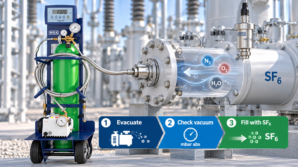
If an SF₆ gas compartment has been opened for installation, repair or maintenance work, ambient air will subsequently be present inside it. This air consists mainly of nitrogen and oxygen and also contains water vapor. If the equipment were then simply filled with SF₆ to the specified filling pressure, these foreign gases would not disappear. They would merely remain inside the closed gas compartment together with the added SF₆.
Proper refilling therefore first requires evacuation. The gas compartment is not flushed with SF₆, but evacuated to a defined absolute residual pressure using a suitable vacuum pump. This removes most of the air present. At the same time, the vacuum supports the removal of water vapor and the outgassing of moist surfaces.
However, the quality of this process step cannot be assessed solely from the nameplate specification of the vacuum pump. A pump may, for example, achieve a very low ultimate pressure while the pressure inside the actual gas compartment remains considerably higher because of long hoses, small cross-sections, leaking connections, closed valves or outgassing surfaces.
The decisive factor is therefore the actual condition reached throughout the entire connected gas volume.
A second important phase follows evacuation: The vacuum is isolated from the pump and observed over a defined period. A pressure rise may indicate a leak, but it can also be caused by moisture, outgassing, temperature changes or dead volumes that have not been fully evacuated. A vacuum hold test is therefore a valuable diagnostic tool, but it must not be confused with a later leak test of the system under operating pressure.
Only after the vacuum has been accepted in accordance with the equipment manufacturer’s specifications should the gas compartment be filled in a controlled manner. The filling condition and gas quality must then be assessed separately. Correct gas pressure does not automatically mean correct gas density – and correct gas density does not confirm that purity and moisture meet the required specifications.
The key point is: High-quality SF₆ filling does not begin at the gas cylinder, but with the vacuum. Actual gas-compartment pressure, vacuum hold testing, dry service lines, controlled filling and subsequent gas-quality testing form one continuous process chain.
Table of Contents
- When does an SF₆ gas compartment need to be evacuated?
- Correctly distinguish evacuation, recovery and filling
- Why residual air in the gas compartment is problematic
- What does vacuum level mean technically?
- Why vacuum should always be assessed as absolute pressure
- How the vacuum level determines the theoretical residual-air fraction
- Do not confuse pump ultimate pressure with gas-compartment pressure
- Why evacuation time alone is not a quality criterion
- Moisture and outgassing during evacuation
- What a vacuum hold test actually shows
- Evacuate service lines and fittings as well
- Fill SF₆ in a controlled manner after successful evacuation
- Distinguish filling pressure, temperature and gas density
- Assess gas quality after filling
- Distinguish new and reused SF₆
- Systematically diagnose typical evacuation errors
- Which standards are relevant to the process?
- Suitable SF₆ service and measurement equipment from ICS Schneider
- Conclusion
- Frequently asked questions about evacuating SF₆ gas compartments
1. When does an SF₆ gas compartment need to be evacuated?
Whether complete evacuation is required depends on what previously happened to the gas compartment.
If closed SF₆ equipment has merely been topped up and the actual gas compartment has not been opened, the existing gas content is not normally simply evacuated. In this case, the main task is to remove air and moisture from the newly connected filling hoses, adapters, valves and service fittings before the connection to the SF₆ gas compartment is opened.
The situation is different after the gas compartment has been opened. As soon as the equipment has been vented, ambient air and atmospheric moisture are present within the volume intended for the insulating gas. Before complete refilling, this gas compartment must be evacuated in accordance with the operating and service instructions of the equipment manufacturer.
The subsequent process history is therefore also decisive after SF₆ recovery. If the closed equipment has only been emptied and has not subsequently been opened, the starting condition is different from that after a repair during which the gas compartment was exposed to ambient air for an extended period.
The work instruction should therefore always clarify first whether only a service volume, a completely vented gas compartment or another defined system volume needs to be evacuated.
2. Correctly distinguish evacuation, recovery and filling
In everyday terminology, the terms extracting and evacuating are sometimes used interchangeably. For SF₆ service work, however, this distinction is important because different equipment and process objectives are involved.
| Process step | What is present in the gas compartment? | Objective |
|---|---|---|
| Recover SF₆ | SF₆ or used insulating gas | Transfer the gas from the equipment into a suitable storage vessel with the lowest possible emissions |
| Evacuate gas compartment | Air, nitrogen and/or residual moisture after opening or venting | Prepare the gas compartment for clean refilling |
| Fill SF₆ | Evacuated gas compartment | Establish the defined filling condition using suitable insulating gas |
An SF₆ vacuum compressor used for gas recovery therefore performs a different task from a vacuum pump used to prepare the compartment for filling.
The WIKA GVC-10, for example, is designed for SF₆ extraction and, in combination with the transfer unit, can evacuate SF₆ gas compartments to a residual pressure below 5 mbar abs. The WIKA GVP-10, on the other hand, is specifically intended for evacuating air or nitrogen in preparation for filling and achieves a significantly lower ultimate pressure.
The word “vacuum” in a device designation alone therefore does not indicate which process step the unit is designed for.
3. Why residual air in the gas compartment is problematic
If air remains in the gas compartment after maintenance and SF₆ is subsequently added, a gas mixture is created. The SF₆ fraction is then correspondingly lower than when a correctly evacuated volume is filled.
This changes the composition of the insulating medium. In addition, ambient air introduces water vapor into the gas compartment.
However, the electrical design of an SF₆ gas-insulated switchgear system is based on a defined gas composition and a defined gas condition. Foreign gases and moisture therefore cannot simply be ignored because the final pressure gauge reading appears correct.
This is where a common misunderstanding arises: The filling pressure initially describes the mechanical condition of the gas. It does not clearly indicate which gases are contributing to that pressure.
A gas compartment can therefore have the specified pressure while still containing an undesirable proportion of residual air or moisture.
4. What does vacuum level mean technically?
During evacuation, the pressure in the gas compartment is gradually reduced. The lower the remaining absolute pressure, the fewer gas molecules remain in the volume.
A perfect vacuum would correspond to an absolute pressure of 0 bar. This condition cannot be achieved technically and is not required for practical SF₆ filling.
Instead, the equipment manufacturer defines a permissible evacuation process or acceptance criterion.
The vacuum pump must be capable of reaching this level reliably under the actual conditions of the connected volume.
The WIKA GVP-10, for example, provides a pumping speed of up to 10 m³/h and an achievable ultimate pressure of ≤ 0.02 mbar abs. Larger filling carts can be equipped with more powerful or two-stage pumps capable of reaching even lower ultimate pressures.
However, these technical pump specifications must not be confused with a general requirement that every SF₆ gas compartment must be evacuated to exactly 0.02 mbar. The required acceptance criterion is specific to the equipment.
5. Why vacuum should always be assessed as absolute pressure
In normal pressure measurements, gauge pressure is often used. A pressure gauge can, for example, display −0.9 bar, indicating that its measured pressure is 0.9 bar below the current atmospheric pressure.
For assessing the quantity of gas remaining in an evacuated gas compartment, however, absolute pressure is decisive.
A value such as:
0.1 mbar abs.
is unambiguous and independent of the current atmospheric pressure.
A specification such as “99.9% vacuum” or a negative gauge-pressure reading is significantly less suitable for precise evaluation because, in the deep-vacuum range, large differences in the remaining gas fraction can be hidden behind apparently very similar percentage values.
For documentation and acceptance criteria, it should therefore be clearly stated whether a value is expressed in mbar abs., Pa abs. or another absolute pressure unit.
6. How the vacuum level determines the theoretical residual-air fraction
Under idealized conditions, the relationship between evacuation pressure and the later residual-air fraction can be illustrated very clearly.
If a gas compartment is evacuated to an absolute residual pressure pV and then filled with SF₆ to an absolute final pressure pF, the theoretical fraction of remaining air is approximately:
xair ≈ pV / pF
The following example uses a final total pressure of 6 bar abs. purely for illustration. It is not a general specification for switchgear.
| Residual pressure before filling | Theoretical residual-air fraction at 6 bar abs. | Approximate magnitude |
|---|---|---|
| 20 mbar abs. | 0.333% | approx. 3,330 ppm |
| 1 mbar abs. | 0.0167% | approx. 167 ppm |
| 0.1 mbar abs. | 0.00167% | approx. 16.7 ppm |
| 0.02 mbar abs. | 0.000333% | approx. 3.3 ppm |
| 0.002 mbar abs. | 0.000033% | approx. 0.33 ppm |
This calculation applies only to an ideal, homogeneous system at comparable temperatures. In real switchgear, outgassing, surface moisture, dead volumes, leaks and incompletely evacuated service volumes must also be considered.
The table is therefore not a substitute for the equipment manufacturer’s specifications. However, it clearly illustrates why a low absolute residual pressure effectively reduces the possible proportion of foreign gas.
7. Do not confuse pump ultimate pressure with gas-compartment pressure
A data sheet specifies the achievable ultimate pressure of a vacuum pump under defined conditions. In a real service setup, however, hoses, valves, couplings, adapters and sometimes long piping sections are located between the pump and the actual gas compartment.
Each of these components limits the effective pumping performance.
Especially at deep vacuum, a small line cross-section can significantly increase the evacuation time. At the same time, leaks or outgassing materials can prevent the theoretical pump ultimate pressure from being reached in the gas compartment at all.
A vacuum measuring instrument should therefore be positioned, or the measuring setup should be designed, so that the relevant condition of the gas compartment is assessed rather than only the pressure immediately at the pump inlet.
The statement “the pump reaches 0.02 mbar” alone is not proof that the entire equipment to be filled has also reached this pressure.
8. Why evacuation time alone is not a quality criterion
In practice, fixed times are often used: for example, evacuating for a specified number of minutes or hours and then filling.
Such a time specification may form part of a manufacturer’s procedure, but it should not be confused with physical verification of the vacuum.
The required time depends on the volume of the gas compartment, pump performance, line cross-sections, initial condition, temperature, surface moisture and many other factors.
A small, dry gas compartment can reach a stable vacuum considerably faster than a large item of equipment that has remained open for an extended period.
A reliable assessment therefore considers not only pump operating time, but also the actual absolute pressure reached and its behavior after the pump is isolated.
9. Moisture and outgassing during evacuation
Removing water vapor is one of the important reasons for evacuation.
However, moisture is not present exclusively as freely moving water vapor in the gas compartment. Water can be adsorbed on internal surfaces or stored within hygroscopic materials.
As the gas pressure decreases, some of this moisture can gradually return to the gas phase. This can cause the pressure to fall more slowly than expected even while the pump is operating.
After the pump has been switched off or isolated, the pressure may then rise again even though there is no significant external leak.
This effect is one reason why a stabilization and hold phase is valuable.
Particularly after extended opening times, high ambient humidity or work on internal components, it should therefore not be assumed that the gas compartment is sufficiently dry simply because a particular minimum value appeared briefly on the vacuum gauge.
10. What a vacuum hold test actually shows
During a vacuum hold test, the evacuated gas compartment is separated from the pump or isolated from it using a valve. The change in absolute pressure is then observed over a defined period.
If the vacuum remains largely stable, this indicates that the gas compartment and connected service volumes are sufficiently tight and have largely completed outgassing.
If the pressure rises significantly, several possible causes must be considered.
An external leak can allow ambient air to enter the gas compartment. Moist or porous surfaces can also continue to outgas. A section of the equipment that was accidentally isolated may release additional gas after a valve is opened. Temperature changes also influence pressure.
The pressure trend over time is therefore often more informative than a single reading.
A continuous pressure rise can more strongly indicate a permanent gas ingress, whereas an initially rapid increase that subsequently levels off may also be caused by outgassing. Reliable differentiation, however, requires knowledge of the specific equipment and, where necessary, further leak testing.
In particular, a vacuum hold test does not automatically replace a subsequent SF₆ leak test at the intended operating pressure.
11. Evacuate service lines and fittings as well
Even a perfectly evacuated gas compartment can be contaminated again during subsequent filling if the filling hose contains ambient air.
The relevant service volume therefore includes not only the visible hose, but also pressure regulators, manifolds, adapters, couplings and enclosed valve chambers.
The service setup should be designed so that this entire gas path can be evacuated before the connection to the equipment is opened.
Every unnecessary adapter increases the volume, adds potential leak points and makes valve operation less straightforward.
Hoses designed for SF₆ applications, such as the WIKA GCH-08 or GCH-20, are vacuum- and pressure-resistant and designed for high gas tightness. A conventional pneumatic or hydraulic hose should not be considered equivalent SF₆ service equipment solely because of its pressure rating.
12. Fill SF₆ in a controlled manner after successful evacuation
Once evacuation has been completed successfully, the actual gas-filling process begins.
Care must be taken not to unintentionally reintroduce ambient air into the previously evacuated gas compartment. The valve sequence, couplings and pressure regulators must therefore be operated according to the specified service procedure.
SF₆ is transferred in a controlled manner from a suitable gas container through the prepared gas path into the equipment.
The filling process should not be unnecessarily fast. Rapid expansion and pressure changes can cause considerable temperature differences between the gas cylinder, service line and gas compartment. As a result, the pressure visible during filling can differ from the later equilibrium value.
Depending on the equipment, the target filling condition can be controlled using a specified gas mass, a temperature-related filling pressure, a normalized gas density or a combination of these parameters.
The specifications of the respective switchgear manufacturer are decisive.
13. Distinguish filling pressure, temperature and gas density
SF₆ pressure depends on temperature. If a given gas mass in a closed volume is heated, the pressure increases. If the same gas cools, the pressure falls again.
A single current pressure-gauge reading can therefore not provide a complete assessment of the filling condition without reference to temperature.
Particularly after filling, the gas temperature may still differ from the temperature of the equipment. A more stable condition is only reached after sufficient temperature equalization.
Gas-density monitors and gas-density sensors therefore account for the influence of temperature. Modern electronic sensors measure pressure and temperature and use these values to determine a temperature-compensated density value.
Pressure and gas density therefore answer different questions: Current pressure describes the instantaneous thermodynamic state. Temperature-compensated gas density is much better suited to monitoring the amount of gas present, or the filling condition, within the closed gas compartment.
However, neither quantity provides information about whether undesirable moisture or foreign gases are present.
14. Assess gas quality after filling
Depending on the equipment, service specification and origin of the gas, additional quality checks may be required after filling.
The most important parameters include moisture and gas composition or SF₆ purity. In gas that has already been used or electrically stressed, decomposition products may also be relevant.
Purity measurement is particularly useful if an undesirable proportion of foreign gas is suspected. If the gas compartment was not sufficiently evacuated, for example, the remaining air reduces the SF₆ fraction in the final gas mixture.
Moisture measurement, on the other hand, determines how much water vapor or residual moisture is present in the gas. Depending on the test method, this parameter can be expressed as a dew or frost point or as a ppm value, among other formats.
The WIKA GA11 combines moisture and gas-composition or purity measurement and can, depending on its configuration, also determine decomposition products.
Gas analysis should be performed in such a way that the SF₆ extracted for measurement is not unnecessarily released into the environment. Modern analysis systems therefore allow, for example, the measured gas to be pumped back into the gas compartment being tested or collected in suitable external containers.
15. Distinguish new and reused SF₆
When assessing gas quality, the origin of the gas to be filled is decisive.
IEC 60376 contains the relevant specifications for technical-grade SF₆ intended for use in electrical equipment.
Recovered SF₆ from previously operated electrical equipment represents a different starting condition. During operation and handling, moisture, foreign gases and – following electrical stress – decomposition products can enter the gas.
IEC 60480 provides criteria and test methods for the reuse of recovered SF₆ and corresponding treated gas mixtures.
For recovered gas, the statement “SF₆ is present” is therefore not sufficient as proof of quality. Before reuse, it must be determined whether the gas meets the criteria required for the intended application or whether it first needs to be processed.
Careful evacuation of the equipment cannot improve poor-quality filling gas. Likewise, high-quality new gas cannot automatically compensate for insufficiently evacuated and moist equipment.
16. Systematically diagnose typical evacuation errors
| Observation | Possible cause | Recommended check |
|---|---|---|
| Vacuum does not reach the specified value | Leak, insufficient line cross-section, valve position or significant outgassing | Check service path, valves, connections and pressure trend |
| Pump indicates deep vacuum but the gas compartment does not | Pressure drop or low conductance in the vacuum path | Check measuring point and hose cross-section |
| Pressure initially rises after isolation and then stabilizes | Outgassing or residual moisture possible | Extend stabilization time and compare the trend with the manufacturer’s specification |
| Pressure continues to rise throughout the hold test | Leak or continuing gas ingress possible | Investigate tightness and non-evacuated partial volumes |
| Purity is too low after filling | Residual air in gas compartment or service volume, unsuitable filling gas | Check evacuation record and gas source |
| Moisture is too high after filling | Moist internal surfaces, insufficiently evacuated service lines or moist gas | Investigate evacuation, service lines and gas quality separately |
| Filling pressure is correct, but gas density is later incorrect | Temperature during filling was not sufficiently taken into account | Check temperature equalization and temperature-compensated filling condition |
17. Which standards are relevant to the process?
In Germany, DIN EN IEC 62271-4 (VDE 0671-4):2024-06 is particularly relevant to the handling of insulating and switching gases in high-voltage equipment. It is based on IEC 62271-4:2022 and covers gas-handling procedures during installation, commissioning, repair, maintenance, operation and end-of-life.
The standard specifies minimum requirements. The manufacturer of the specific equipment may define additional or more stringent requirements in its operating or service instructions.
For new technical-grade SF₆, DIN EN IEC 60376 (VDE 0373-1):2019-10 or IEC 60376:2018 is relevant.
For the reuse of recovered SF₆ and its treated mixtures, DIN EN IEC 60480 (VDE 0373-2):2020-06 or IEC 60480:2019 is relevant.
For practical work, this means that pump capacity, vacuum level, hold time and quality control should not be derived solely from general experience. The current manufacturer documentation for the specific equipment, the applicable standards and the defined service process are decisive.
18. Suitable SF₆ service and measurement equipment from ICS Schneider
ICS Schneider Messtechnik offers WIKA solutions for evacuation, filling, gas recovery, gas-quality analysis and permanent condition monitoring. An overview can be found under SF₆ Gas Solutions.
WIKA GVP-10 – vacuum pump for filling preparation
The WIKA GVP-10 is specifically designed for evacuating air or nitrogen from SF₆ gas compartments before filling.
It offers a pumping speed of up to 10 m³/h and an achievable ultimate pressure of ≤ 0.02 mbar abs. An optional precision vacuum measuring instrument can be used.
This makes it particularly suitable for mobile service work in which an opened gas compartment needs to be evacuated in a controlled manner before refilling.
The GVP-10 must not be confused with the GVC-10. The GVC-10 is an SF₆ vacuum compressor for recovering the existing insulating gas, whereas the GVP-10 is used to remove air or nitrogen in preparation for filling.
WIKA GFU08 – evacuation and filling in one mobile system
The WIKA GFU08 filling carts are available in modular versions for different service tasks.
The GFU08-E and GFU08-C versions feature a vacuum pump for preparing the gas compartment. The GFU08-C additionally incorporates a scale, enabling the transferred gas mass to be monitored as well as the evacuation process.
Versions with higher pumping capacity and lower achievable ultimate pressure are available for larger gas volumes.
WIKA GA11 – checking gas quality after filling
The WIKA GA11 is a portable analysis instrument for assessing the quality of SF₆ and alternative insulating gases.
Moisture and gas composition or purity are included in the standard measurement. Depending on the configuration, decomposition products can also be measured.
The GA11 is therefore suitable for final checks after maintenance and filling work when not only the filling condition but also the actual gas quality needs to be assessed.
The handling of the sample gas is designed for low-emission operation. Among other options, the analyzed gas can be pumped back into the gas compartment being tested.
WIKA GDHT-20 – permanent monitoring of gas density and moisture
The WIKA GDHT-20 measures pressure, temperature and moisture of the insulating gas.
A temperature-compensated gas-density value is determined from pressure and temperature. This makes it possible to distinguish changes in the actual filling condition from normal temperature-related pressure fluctuations.
The additional moisture information enables permanent condition monitoring even after the service work has been completed.
SF₆ hoses and filling sets
Suitable components for gas-tight service setups are available under SF₆ Hoses and Gas Refill Sets.
Especially during evacuation work, the entire gas path must be vacuum-resistant and sufficiently gas-tight. A high-performance service unit can only transfer its technical capabilities to the gas compartment if the hoses, couplings and adapters are suitable as well.
19. Conclusion
Evacuation before refilling with SF₆ is far more than a preparatory step. It directly determines how much ambient air and moisture can remain in the subsequently closed gas compartment.
The decisive factor is not the nominal ultimate pressure of the vacuum pump alone, but the actual absolute pressure reached throughout the complete connected gas compartment.
The lower this residual pressure, the smaller the remaining air fraction after filling under idealized conditions. In the real system, outgassing, moisture, dead volumes, line cross-sections and potential leaks also influence the result.
A controlled stabilization or vacuum-hold phase therefore forms part of the technical assessment after the actual evacuation. A pressure rise must be interpreted and must not automatically be attributed solely to a leak.
The entire service path is equally important. Air in a filling hose or valve manifold can contaminate a previously correctly evacuated gas compartment again as soon as the connection is opened.
After evacuation, controlled filling is carried out in accordance with the manufacturer’s instructions. The current filling pressure must be considered together with the gas temperature. For long-term evaluation, temperature-compensated gas density is more informative than a single uncompensated pressure value.
However, gas density does not replace gas-quality analysis. Residual air, moisture and, where applicable, decomposition products require their own measured variables.
A technically sound recommissioning process therefore follows a clear sequence:
Prepare gas compartment → fully evacuate → stabilize vacuum → hold and assess vacuum → check service path → fill to defined condition → allow temperature equalization → check gas density and, where required, gas quality → document.
Clearly separating these steps avoids the most common misconception in SF₆ service work: the assumption that a correct final pressure automatically means that the gas filling is also dry, pure and properly prepared.
20. Frequently asked questions about evacuating SF₆ gas compartments
Does an SF₆ system need to be completely evacuated before every top-up?
No. If SF₆ is still present in a closed gas compartment and the compartment has not been opened, it is not simply evacuated for a normal top-up. However, air-free service lines and fittings must be prepared accordingly before the connection to the equipment is opened.
When does the entire gas compartment need to be evacuated?
Typically after the gas compartment has been opened or vented and ambient air and moisture have entered the volume intended for the insulating gas. The specific procedure is determined by the equipment manufacturer.
Why can’t the air simply be displaced with SF₆?
In a closed gas compartment, part of the air would remain in the system or SF₆ would be released during flushing. Controlled evacuation reduces air and water vapor without such unnecessary flushing.
What vacuum level must be reached before filling?
There is no single value that can be applied without verification to every switchgear system. The required vacuum level and associated hold or stabilization times must be determined from the documentation of the respective equipment and the applicable procedures.
The GVP-10 reaches 0.02 mbar. Does that mean the system must always be evacuated to 0.02 mbar?
No. 0.02 mbar abs. is the specified achievable ultimate pressure of the vacuum pump. It is a device characteristic and not automatically the prescribed acceptance criterion for every switchgear system.
Why should vacuum be specified in mbar absolute?
Only absolute pressure clearly describes how much gas remains in the volume. Percentage vacuum or negative gauge-pressure values are less unambiguous, particularly in the deep-vacuum range.
How is the residual-air fraction related to evacuation pressure?
Under idealized conditions, the subsequent residual-air fraction approximately corresponds to the ratio of the residual pressure before filling to the final absolute total pressure. The lower the evacuation pressure, the smaller the theoretical remaining proportion of foreign gas.
Is the pump ultimate pressure the same as the pressure in the gas compartment?
Not necessarily. Hoses, valves, small cross-sections, leaks and outgassing can cause the gas compartment to remain at a higher pressure than the region immediately at the pump.
Why does the pressure rise again after the vacuum pump is switched off?
Possible causes include a leak, outgassing moisture or other substances, incompletely evacuated partial volumes or temperature changes. The pressure trend must therefore be assessed together with the history of the equipment.
Is a vacuum hold test also an SF₆ leak test?
No. A vacuum hold test provides valuable information about the evacuated condition but does not automatically replace a leak test of the equipment later filled with SF₆ and operating under pressure.
Why must the filling hose also be evacuated?
A non-evacuated hose contains ambient air and moisture. When the equipment valve is opened, this volume would be introduced into the previously prepared gas compartment.
What is the difference between the GVP-10 and GVC-10?
The GVP-10 is a vacuum pump for removing air or nitrogen in preparation for filling. The GVC-10 is a vacuum compressor for recovering SF₆ from gas-filled equipment.
Can the equipment be filled immediately after reaching the vacuum value?
This depends on the manufacturer’s specification. A stabilization or hold phase is often required to check whether the pressure remains stable after the pump has been isolated.
Why can moisture still be a problem despite a deep vacuum?
Moisture can be bound to surfaces or stored in materials and may only gradually outgas during evacuation. Briefly reaching a low pressure therefore does not automatically confirm that the gas compartment is completely dry.
Can gas quality be assessed from the filling pressure?
No. Pressure does not clearly indicate whether the gas is sufficiently pure and dry. Foreign gases or moisture may still be present despite an apparently correct filling pressure.
What is the difference between filling pressure and gas density?
Current pressure changes with gas temperature. Temperature-compensated gas density describes the filling condition of a closed gas compartment far more independently of normal temperature fluctuations.
Why should temperature equalization be allowed after filling?
During gas transfer, the gas cylinder, service line and gas compartment can heat up or cool down differently. The pressure measured immediately during filling can therefore differ from the later equilibrium condition.
Which gas-quality values are relevant after filling?
Depending on the application and service specification, moisture and gas composition or purity are particularly relevant. For SF₆ that has already been used or electrically stressed, decomposition products may also need to be checked.
Which standard applies to new SF₆?
IEC 60376, or the corresponding DIN EN IEC edition, is relevant for technical-grade SF₆ intended for use in electrical equipment.
Which standard applies to reused SF₆?
IEC 60480 or DIN EN IEC 60480 covers specifications and criteria for the reuse of recovered SF₆ and corresponding gas mixtures.
Which standard covers actual SF₆ gas handling?
For high-voltage switchgear, DIN EN IEC 62271-4 (VDE 0671-4):2024-06, based on IEC 62271-4:2022, is the current central standard covering handling procedures for gases used for insulation and/or switching. Additional requirements from the respective equipment manufacturer must also be observed.
What information does ICS Schneider require to select suitable evacuation and filling equipment?
Useful information includes gas-compartment volume, existing insulating gas, required evacuation pressure, desired evacuation time, equipment connection and coupling system, service hose length, specified filling pressure or target gas density, required mass-balance monitoring and requirements for gas-quality and moisture testing.