


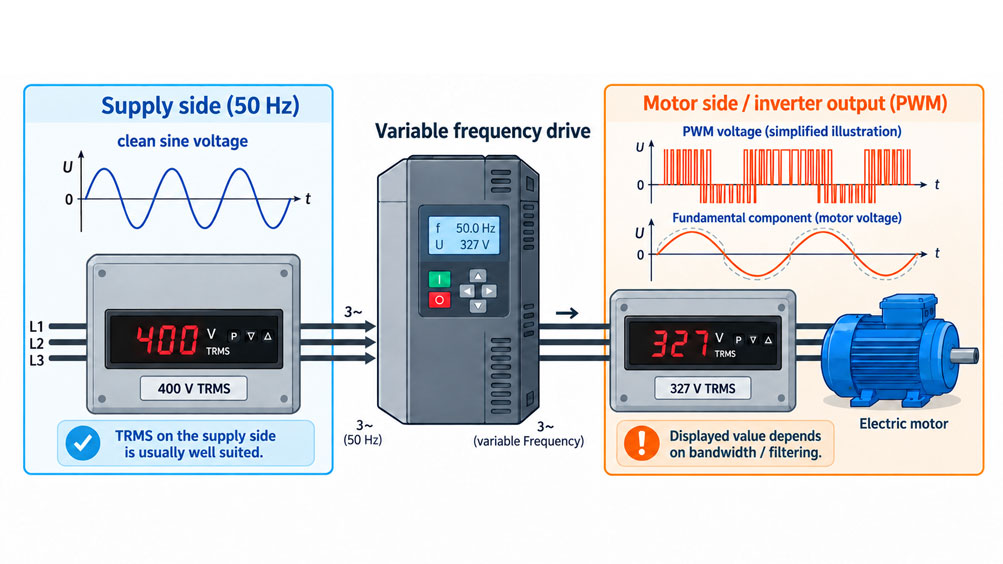
A digital panel meter in a control cabinet is often used to continuously display the voltage or current of a drive. With a motor operated directly from a sinusoidal mains supply, this task is relatively straightforward. If the motor is supplied by a frequency inverter, however, the electrical measurement task changes fundamentally.
On the mains side of the frequency inverter, the mains fundamental frequency is still present. However, the current drawn can deviate significantly from a sinusoidal waveform due to the rectifier, DC link and other power electronics. On the motor side, by contrast, a pulse-width-modulated output voltage is generated. Its fundamental component has the variable frequency required by the motor, while the voltage also contains fast switching transitions and high-frequency components.
A True-RMS measuring instrument is generally designed to determine the RMS value even for non-sinusoidal signals. However, this does not automatically mean that every panel meter labeled “TRMS” can correctly measure every frequency inverter output.
Additional decisive factors are the frequency bandwidth of the measuring input, filter behavior, permissible signal waveform, measuring range and the question of which RMS value is actually required. Should the complete PWM RMS value including relevant switching components be measured, or is the fundamental component that is primarily relevant to motor operation of greater interest?
Two technically faultless measuring instruments can therefore display different voltage values on the same frequency inverter if their bandwidths or filter concepts differ.
The key point is: True RMS describes the method used to calculate the RMS value – it does not automatically guarantee full suitability for PWM output signals. On a frequency inverter, measuring point, signal waveform, fundamental frequency, switching frequency and measurement bandwidth must be considered together.
Table of Contents
- 1. First determine: mains side or motor side?
- 2. What does True RMS actually mean?
- 3. Why the output voltage of a frequency inverter is special
- 4. Distinguishing the fundamental component from the total PWM RMS value
- 5. Why frequency bandwidth is decisive
- 6. Do not confuse output frequency with switching frequency
- 7. Why output current and output voltage look different
- 8. Also consider peak value and crest factor
- 9. What role does a low-pass or VFD filter play?
- 10. RMS measurement and frequency measurement are two different functions
- 11. Measuring time is not the same as input bandwidth
- 12. Correctly planning the connection of a panel meter
- 13. Do not use voltage and current transformers on PWM outputs without verification
- 14. Consider EMC in the control cabinet
- 15. Why the inverter display and panel meter can differ
- 16. Systematically diagnosing typical incorrect readings
- 17. Selection criteria for a True-RMS panel meter
- 18. Suitable panel meters from ICS Schneider
- 19. Conclusion
- 20. Frequently asked questions about True-RMS panel meters on frequency inverters
1. First determine: mains side or motor side?
The phrase “measurement on the frequency inverter” is technically too vague. A frequency inverter has several electrically very different sections.
When selecting the measuring instrument, at least the mains input and motor output must be distinguished.
| Measuring point | Typical signal waveform | Special characteristic |
|---|---|---|
| Mains input | Voltage predominantly sinusoidal at mains frequency | Current can be strongly distorted by the rectifier |
| DC link | DC voltage with superimposed ripple | Not a conventional AC TRMS measurement task |
| Motor output | PWM voltage with variable fundamental frequency | High switching components and steep voltage edges |
On the mains side, for example, a 50 Hz or 60 Hz voltage system is still present. For voltage indication, this measurement is therefore much closer to a conventional mains voltage measurement.
The input current, however, can be significantly distorted. This is precisely where True-RMS measurement offers a major advantage over a simple average-responding, RMS-calibrated measurement.
On the motor side, the situation is fundamentally different. The voltage is generated from the DC-link voltage by fast semiconductor switches. A directly connected panel meter therefore does not see a clean sinusoidal voltage, but a sequence of PWM pulses.
The question “Is the instrument True RMS?” is therefore only the starting point for selecting a device on the motor side.
2. What does True RMS actually mean?
The RMS value of a voltage describes the DC voltage that would produce the same heating power in a purely resistive load as the time-varying voltage being measured.
For a periodic voltage, the mathematical relationship is:
URMS = √[(1/T) · ∫ u²(t) dt]
For a pure sine wave, this results in the familiar relationship between peak value and RMS value.
For a distorted waveform, however, simple averaging with a sine-wave-related correction factor is not sufficient. A genuine True-RMS method evaluates the actual waveform within its permissible operating range.
The last part is crucial: within its operating range.
Every real measuring instrument has a finite bandwidth. Very high frequency components are attenuated by the input circuitry or are no longer processed completely.
The designation “True RMS” therefore does not mean that an instrument theoretically includes frequency components from 0 Hz to infinity.
3. Why the output voltage of a frequency inverter is special
A modern frequency inverter usually generates the motor voltage using pulse-width modulation.
The output semiconductors switch the DC-link voltage at high speed. The timing ratio of the individual pulses produces a fundamental component with the required voltage and frequency for the motor.
In simplified terms, one motor phase can therefore simultaneously contain:
- a fundamental frequency corresponding to the required motor speed,
- a PWM switching frequency,
- sidebands and other high-frequency components,
- steep voltage edges and
- additional overshoots depending on the cable and motor.
A panel meter must therefore not only withstand the signal amplitude. It must also be defined which frequency range its RMS measurement method evaluates.
4. Distinguishing the fundamental component from the total PWM RMS value
For a distorted periodic voltage, the total RMS value can be considered in simplified form as a combination of the fundamental component and additional frequency components.
Under the appropriate mathematical conditions:
URMS,total2 = U12 + U22 + U32 + …
Here, U1 is the fundamental component and the other terms represent additional frequency components.
For a PWM output, an important question therefore arises:
Should the complete RMS value including the detected switching components be displayed, or should the motor-related fundamental component be evaluated?
Both can be technically meaningful measurement tasks. However, they are not the same measured quantity.
During commissioning of a drive, the fundamental component acting on the motor is often of primary interest. When investigating electrical stress, losses or EMC, higher-frequency components may also be relevant.
This is why measuring instruments for frequency inverter applications are available with special low-pass or VFD functions. These suppress part of the high-frequency PWM components so that the fundamental component can be evaluated more effectively.
5. Why frequency bandwidth is decisive
The input bandwidth determines which frequency components of a signal the measuring circuit can process with sufficient accuracy.
A simple example illustrates the problem.
A frequency inverter provides a motor output fundamental frequency of:
50 Hz
and operates, for example, with a PWM switching frequency of:
4 kHz
These values are used here only for illustration.
A measuring instrument with a very low input bandwidth may essentially detect the fundamental component or other low-frequency signal components.
A significantly wider-band instrument may, on the other hand, include additional PWM components in its RMS calculation.
The two instruments may therefore display different RMS values even though neither is necessarily defective.
When selecting a product, the manufacturer should therefore specify a sufficiently clear permissible frequency range or input bandwidth if the instrument is to be connected directly to a PWM output.
6. Do not confuse output frequency with switching frequency
Several completely different frequencies are often specified simultaneously for a frequency inverter.
| Frequency | Meaning |
|---|---|
| Mains frequency | Typically 50 or 60 Hz at the inverter input |
| Output or fundamental frequency | Largely determines the electrical rotating-field frequency of the motor |
| PWM / switching frequency | Frequency at which the power semiconductors are switched |
| Additional frequency components | Harmonics, sidebands and interference |
If the data sheet of a panel meter only states “50/60 Hz” for its power supply, for example, this does not automatically describe the permissible frequency range of the measuring input.
Supply frequency and measurement bandwidth are two different technical specifications.
This distinction is particularly important when selecting a panel meter for use with a frequency inverter.
7. Why output current and output voltage look different
The motor inductance smooths a considerable proportion of the high-frequency current components. As a result, the motor current is typically much closer to a sinusoidal waveform than the directly switched PWM output voltage.
This does not mean, however, that the current is perfectly sinusoidal.
Depending on motor, load, control method and switching frequency, high-frequency components can also occur in the current.
A True-RMS current measuring instrument can therefore be very useful for output-current measurement, provided that its bandwidth, current range and input technology are suitable for the application.
Voltage and current should nevertheless not be assessed using the same general assumption.
A measuring method that provides good results for motor current does not automatically provide the same level of validity for PWM voltage.
8. Also consider peak value and crest factor
The RMS value alone does not describe all characteristics of a distorted signal.
An important additional parameter is the peak value.
The crest factor is defined as:
CF = Upeak / URMS
For an ideal sine wave, this value is approximately:
√2 ≈ 1.414
For strongly distorted signals, the ratio may differ.
A True-RMS instrument can only measure a waveform correctly if both the RMS value and the occurring signal peaks remain within its permissible input range.
When measuring directly at the frequency inverter output, it is therefore not sufficient to check only whether, for example, “600 VAC” is stated in the data sheet. Specifications relating to permissible signal waveforms, peak values and, where applicable, crest factor are equally important.
If such information is not specified by the manufacturer, PWM suitability should not simply be inferred from the TRMS marking.
9. What role does a low-pass or VFD filter play?
A low-pass filter allows lower frequencies to pass while attenuating higher-frequency components.
On a frequency inverter, this can be used deliberately to suppress high-frequency PWM switching components relative to the fundamental component.
This can produce a measured value that is more comparable with the motor-relevant fundamental voltage or with the value shown by the frequency inverter itself.
However, a low-pass filter changes the measured quantity.
The filtered value is no longer identical to the broadband total RMS value of the unfiltered PWM signal.
For this reason, the operationally required value must be defined before selecting the measuring instrument.
A permanently installed control-cabinet display for machine operation may pursue a different measurement objective from a power analyzer used during frequency inverter development.
10. RMS measurement and frequency measurement are two different functions
An AC True-RMS panel meter calculates an RMS value.
A frequency meter, by contrast, determines the repetition rate or period duration of a suitable input signal.
With a clean sinusoidal voltage, both functions can be combined relatively easily.
With a PWM output voltage, however, the frequency meter must be able to distinguish which signal structure is to be regarded as the relevant frequency.
Without suitable filtering, a simple frequency measurement can be influenced by switching edges even though the motor fundamental frequency is the quantity actually required.
A value such as:
Output frequency 37.5 Hz
is therefore a different measured quantity from:
TRMS output voltage 310 V
Different input requirements apply to these two quantities.
11. Measuring time is not the same as input bandwidth
The measuring time of a digital panel meter must also not be confused with its electrical input bandwidth.
An adjustable measuring time of, for example, 0.1 to 10 seconds influences how often a new displayed value is provided or how strongly the value is averaged.
However, it does not automatically indicate the maximum input-signal frequency that can be processed for the RMS calculation.
An instrument may update its display only once per second while internally processing a significantly higher-frequency signal.
Conversely, a very rapidly updated display may still have a limited analog input bandwidth.
For a frequency inverter, at least two different specifications therefore need to be checked:
- measuring or update time and
- frequency range or input bandwidth.
12. Correctly planning the connection of a panel meter
For permanent measurement in a control cabinet, the electrical quantity to be measured must first be clearly defined.
On the mains side of a three-phase frequency inverter, for example, a line-to-line voltage between two line conductors can be monitored.
On the motor side, it must likewise be defined whether a line-to-line voltage U-V, V-W or W-U is to be measured.
An arbitrary measurement from a motor phase to protective earth must not be treated as equivalent to a normal line-to-line voltage measurement. Frequency inverters generate common-mode voltages, so a measurement referenced to PE represents a different signal.
The measuring range, insulation concept and permissible input voltage must therefore match the intended connection method exactly.
It must also be checked whether the panel meter requires a separate auxiliary supply and whether this supply is electrically isolated from the measuring circuit, or how the potentials may be connected according to the manufacturer.
13. Do not use voltage and current transformers on PWM outputs without verification
If a measuring range is extended using a current or voltage transformer, another transmission element is added to the measuring chain.
This transformer also has a limited frequency range.
A conventional voltage transformer designed for 50 Hz mains applications is therefore not automatically suitable for accurately transforming a pulse-width-modulated inverter output voltage to a secondary value.
Magnetization, losses and transmission errors change with frequency.
The same basic principle applies to current transformers. The combination:
Frequency inverter → measuring transformer → panel meter
is only as accurate as the complete transmission chain.
If direct measurement is not possible, both the transformer and the panel meter must therefore be approved for the actual signal waveform present.
14. Consider EMC in the control cabinet
A frequency inverter is also a powerful source of electromagnetic interference.
High rates of voltage change and rapid current changes can couple into nearby measuring and signal cables.
As a result, even a fundamentally suitable panel meter can produce unstable or incorrect readings if the installation is poorly designed.
Measurement, supply and signal cables should therefore be routed in accordance with the equipment and installation requirements.
Unnecessary parallel routing of sensitive measuring signals directly alongside inverter-to-motor cables should be avoided in particular.
Depending on the signal type, twisted cables, suitable shielding and clear separation between power and measurement wiring may be useful or necessary.
Shielding and equipotential bonding must not be connected arbitrarily. The EMC concept of the machine and the manufacturers’ specifications for the installed equipment are decisive.
15. Why the inverter display and panel meter can differ
A common situation in practice is the following:
The frequency inverter displays an output voltage of, for example, 320 V, while an external True-RMS measuring instrument indicates a significantly different value.
This does not automatically mean that one of the devices is defective.
Possible causes include:
| Possible cause | Effect |
|---|---|
| Different measurement bandwidths | PWM components are included to different extents |
| Internal low-pass filter | Display is more strongly oriented toward the fundamental component |
| Inverter calculates rather than directly measures | Displayed value may be derived from modulation index and DC-link voltage |
| Different RMS definitions | Total RMS and fundamental RMS are being compared |
| Measuring instrument outside its bandwidth | Value no longer has the specified accuracy |
| EMC interference | Unstable or systematically shifted indication |
Before comparing values, it is therefore necessary to determine what both devices are actually displaying.
The best agreement between two numbers is not automatically the most important quality criterion. What matters is whether both instruments are measuring the same physical quantity.
16. Systematically diagnosing typical incorrect readings
| Observation | Possible cause | Recommended check |
|---|---|---|
| Panel meter indicates significantly more voltage at the inverter output than expected | High-frequency PWM components are included in the RMS calculation | Check measurement bandwidth and filter concept |
| Displayed value is significantly lower than the reference value | Bandwidth may be too low or input unsuitable | Compare with a suitable reference instrument |
| Value is correct on the mains side but not on the motor side | Panel meter not specified for PWM output | Verify suitability for inverter output with the manufacturer |
| Displayed value changes with PWM switching frequency | Switching components lie within or close to the measurement bandwidth | Compare measurements using different inverter settings |
| Display is very unstable despite constant speed | EMC, signal peaks or unsuitable input filtering | Check wiring and perform reference measurement |
| Frequency value jumps to unrealistic values | PWM edges are being evaluated instead of the fundamental frequency | Use suitable frequency filtering or a separate frequency source |
| Panel meter and frequency inverter show a constant difference | Different definitions of output voltage | Compare the documentation of both devices |
| Abnormal values only occur with long motor cables | Additional high-frequency cable effects | Investigate the waveform using suitable measurement technology |
Reference measurement before permanent installation
Especially for a permanently installed display, it is advisable to first examine the intended measuring point using a reference instrument suitable for frequency inverter applications.
This allows the following to be evaluated:
- fundamental frequency,
- signal waveform,
- RMS value,
- relevant frequency components and
- possible interference signals.
Only then can the requirements for the permanently installed panel meter be determined reliably.
17. Selection criteria for a True-RMS panel meter
The specification “True RMS, 0…600 V” alone is not sufficient for selection.
For an application in the environment of a frequency inverter, at least the following points should be defined:
| Criterion | Why it is relevant |
|---|---|
| Measuring point | Mains input and PWM motor output have different requirements |
| Measured quantity | Voltage, current and frequency require different inputs |
| Measuring range | RMS value must remain within the specified input range |
| Peak value / crest factor | Distorted signals can have significantly higher peaks |
| Fundamental frequency | Variable inverter output frequency must remain within the permissible range |
| Input bandwidth | Determines which PWM and harmonic components are included |
| Filter function | Helps determine whether total RMS or primarily the fundamental component is displayed |
| Measuring time | Influences response and display stabilization |
| Electrical isolation | Relevant for safe integration into the control cabinet and output circuits |
| EMC immunity | Frequency inverters generate high interference levels |
| Output interfaces | Analog output, relays or RS485 may be required for PLC and monitoring systems |
The most important point is that the permissible measurement bandwidth must be known for the specific application.
If it is not stated in the data sheet, it should be clarified with the manufacturer or supplier before direct use at the inverter output.
18. Suitable panel meters from ICS Schneider
ICS Schneider Messtechnik offers numerous analog and digital panel meters for plant and control cabinet applications. An overview can be found under Measuring Instruments for Plant and Control Cabinet Applications and under Digital Panel Meters / Digital Indicators.
IM3 96 × 48 mm – True-RMS panel meter
The IM3 in 96 × 48 mm processes AC voltage and AC current signals as true RMS values.
For the high-voltage version, measuring inputs up to 300 or 600 VAC as well as 1 and 5 AAC are available. The instrument offers a five-digit display, optional analog and relay outputs as well as RS232 or RS485.
For conventional AC monitoring in control cabinets, particularly on the mains side of a frequency inverter, this device class can be of interest.
For direct connection to the PWM motor output, however, the permissible input bandwidth or explicit suitability for the existing PWM waveform must additionally be clarified. The currently available technical documentation specifies TRMS measuring ranges, measurement error and measuring time, but does not state a clear measurement bandwidth for this input.
IM3 96 × 24 mm – compact design
The IM3 in 96 × 24 mm offers a more compact format for control cabinet applications.
This version also operates with True-RMS AC voltage and AC current inputs and is available, among other configurations, with 300 VAC and 5 AAC measuring inputs.
As with every TRMS display, the same principle applies: Suitability for direct connection to a PWM inverter output must not be inferred solely from the designation “True RMS”.
Additional TRMS panel meters
Additional versions can be found under High AC Voltage / AC Current.
Various front-panel formats, measuring ranges and functional configurations are available for permanent AC indication.
CA 8345 for reference and commissioning measurements
If the actual waveform or the power quality of the mains or drive system must first be investigated, a suitable power and power quality analyzer can be useful.
The CA 8345 is suitable for detailed electrical analysis and can, for example, be used during commissioning and for plausibility checks of a subsequently installed permanent display.
For demanding measurements directly on the PWM motor side, however, the analyzer itself must also be verified as suitable for the specific measurement task and required bandwidth.
19. Conclusion
True RMS is an important prerequisite for reliable RMS measurements of distorted electrical signals. However, when working with a frequency inverter, the term alone is not sufficient for selecting a suitable panel meter.
It must first be clearly determined whether the measurement is to be made on the mains side or the motor side.
On the mains side, the mains fundamental frequency is still present. The current in particular can nevertheless be significantly distorted, making true RMS measurement highly advantageous.
On the motor side, by contrast, the voltage is pulse-width modulated, with a variable fundamental frequency and additional high-frequency switching components.
The RMS value displayed by a panel meter therefore depends decisively on its input bandwidth and filtering.
A broadband total RMS value is not automatically identical to the RMS value of the fundamental component. Both can be meaningful depending on the measurement objective.
Output frequency, PWM switching frequency and measurement bandwidth must also not be confused with one another.
For technically reliable selection, at least the following must therefore be considered together:
measuring point → signal waveform → measured quantity → measuring range → frequency range → bandwidth → filtering → connection
If the input bandwidth of a True-RMS panel meter is not specified, direct use on the PWM output of a frequency inverter should not simply be assumed to be suitable.
A prior reference measurement under real operating conditions prevents a permanently installed panel meter from later displaying a stable value that is nevertheless physically defined differently from what was expected.
20. Frequently asked questions about True-RMS panel meters on frequency inverters
Can every True-RMS measuring instrument be used on a frequency inverter?
No. True RMS describes the calculation method used for the RMS value. In addition, measuring range, frequency bandwidth, permissible waveform and, where applicable, crest factor must be suitable for the application.
Why is frequency bandwidth so important?
A PWM output contains significantly higher-frequency components in addition to the motor fundamental frequency. Which of these are included in the RMS calculation depends on the bandwidth of the measuring instrument.
Is the 50/60 Hz frequency stated for the power supply also the measuring frequency range?
No. A 50/60 Hz specification for the device supply initially describes the permissible mains frequency of the auxiliary power supply. The frequency bandwidth of the measuring input is a separate technical parameter.
Why does the True-RMS instrument indicate a higher voltage than the frequency inverter?
One possible reason is that the external measuring instrument includes additional PWM switching components in its RMS value, while the inverter display represents a filtered or calculated fundamental quantity. The definitions of both displayed values must be compared.
Can a True-RMS instrument also indicate too little?
Yes. If relevant frequency components lie outside the input bandwidth, they may be attenuated and the displayed total RMS value may be lower.
What is the difference between fundamental RMS and total RMS?
Fundamental RMS considers only the fundamental frequency. Total RMS can additionally include harmonics and other frequency components, provided they lie within the instrument’s measurement bandwidth.
What does a VFD or low-pass filter do?
Such a filter suppresses high-frequency switching components of the PWM signal. This enables a measurement that is more strongly focused on the fundamental component or the motor-relevant voltage.
Is the output current of a frequency inverter also PWM-shaped?
The motor current also contains switching components, but it is significantly smoothed by the motor inductance. It is typically much closer to a sinusoidal waveform than the output voltage.
Can I connect a conventional AC panel meter to the inverter output?
Only if the manufacturer specifies the instrument for the existing voltage, waveform and frequency components. A simple 50/60 Hz mains measuring range is not automatically sufficient for a PWM application.
Can a 600 V TRMS input always measure a 400 V motor supplied by a frequency inverter?
Not automatically. The RMS range is only one selection criterion. Permissible peak values, input bandwidth, insulation and PWM suitability must also be considered.
What does crest factor mean?
The crest factor describes the ratio between the peak value and RMS value of a signal. Strongly distorted signals can have different peak-to-RMS ratios than an ideal sine wave.
Why is frequency measurement difficult at the PWM output?
In addition to the fundamental frequency, the signal contains numerous switching edges at much higher frequencies. Without suitable filtering or evaluation, a frequency meter can incorrectly interpret these signal components.
Can a conventional 50 Hz voltage transformer be used ahead of the panel meter?
Not without verification at the PWM output. A voltage transformer has a defined frequency range and may transmit high-frequency PWM signals differently from a sinusoidal mains voltage.
Why is the measuring point so important?
The mains input, DC link and motor output of a frequency inverter have completely different waveforms. An instrument that performs very well at one location does not necessarily have the same suitability at another.
Is a high measuring speed the same as high bandwidth?
No. Measuring time or display update rate and electrical input bandwidth are different characteristics. A rapidly updated display can still process only a limited signal frequency range.
Why should I compare the intended panel meter with a reference instrument beforehand?
This makes it possible to determine under real inverter operating conditions which value is actually displayed and whether filtering and measurement bandwidth match the desired measured quantity.
Is the ICS IM3 automatically suitable for direct connection to a frequency inverter output?
The IM3 is specified as a True-RMS panel meter for corresponding AC voltage and current ranges. However, the currently available technical specifications do not publish a clear frequency bandwidth for the TRMS measuring input. For direct use on a PWM motor output, suitability should therefore be technically confirmed in advance for the specific inverter application.
What information does ICS Schneider require to select a suitable panel meter?
Useful information includes the measuring point on the frequency inverter, measured quantity, maximum voltage or current, minimum and maximum output fundamental frequency, PWM switching frequency, required display quantity, whether total RMS or the fundamental component is required, necessary analog or switching outputs, interfaces, auxiliary supply, panel cutout dimensions and the existing EMC environment.