


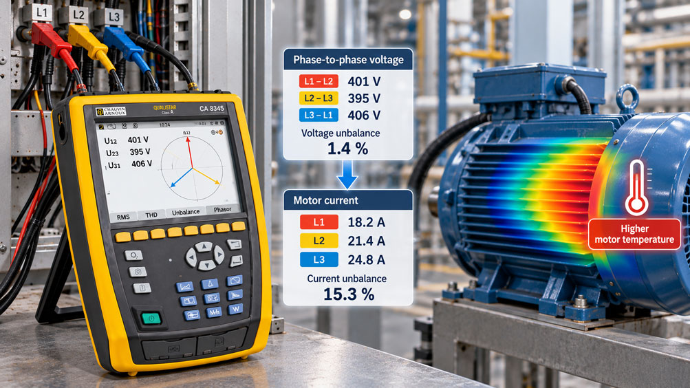
A three-phase motor is designed for a supply system that is as symmetrical as possible. Ideally, the three line-to-line voltages have the same RMS value and are electrically phase-shifted by 120° from one another. In a real industrial installation, however, this ideal condition is not always achieved.
Unevenly loaded phases, long cables, poor terminal connections, fuses and contactor contacts, transformers or faults in the power supply can cause the three voltages at the motor to become unbalanced. At first glance, the differences often appear small: One line-to-line voltage may be a few volts higher, while another is a few volts lower.
For a three-phase motor, even such a seemingly small voltage unbalance can have significantly greater consequences. The motor does not only react with unequal phase currents. The so-called negative-sequence component creates a magnetic field that rotates in the opposite direction to the normal rotating field. This increases electrical losses, particularly the thermal loading of the stator and rotor, and the motor can become significantly hotter.
An important practical finding is therefore: A small voltage unbalance does not automatically mean an equally small current unbalance. In induction motors, the current unbalance can be several times greater than the voltage unbalance.
For a reliable diagnosis, it is therefore not sufficient to measure only one voltage or only the total motor current. All three voltages, all three phase currents, the operating condition and, wherever possible, the time history must be considered together.
The key point is: If a significant current unbalance is detected, it must first be determined whether the cause is already present in the supplying three-phase system or only occurs in the motor or its connection path. Voltage unbalance, current unbalance and motor heating are closely related, but they are not identical.
Table of Contents
- 1. What is voltage unbalance in a three-phase system?
- 2. Why are there different calculation methods?
- 3. Calculating voltage unbalance using the NEMA method
- 4. VUF and negative sequence in power quality analysis
- 5. Why a three-phase motor reacts particularly sensitively
- 6. Why current unbalance can be significantly greater
- 7. How voltage unbalance causes additional heating
- 8. Which limits are appropriate?
- 9. Typical causes of voltage unbalance
- 10. Correctly measuring voltage unbalance at the motor
- 11. Correctly comparing motor currents
- 12. Locating faults between the supply, cable and motor
- 13. Using motor heating as an additional diagnostic parameter
- 14. Do not confuse unbalance with harmonics
- 15. Special considerations for motors operated from frequency converters
- 16. Why long-term recording is often useful
- 17. Systematically evaluating typical fault patterns
- 18. Safety when measuring in three-phase systems
- 19. Suitable measurement technology from ICS Schneider
- 20. Conclusion
- 21. Frequently asked questions about voltage unbalance
1. What is voltage unbalance in a three-phase system?
In an ideally balanced three-phase system, all three voltages have the same magnitude and are phase-shifted by 120° from one another.
An unbalance exists when this relationship is no longer fully maintained. Both the voltage magnitudes and the phase angles can differ.
For practical troubleshooting, the three line-to-line voltages are often measured first:
UL1-L2, UL2-L3 and UL3-L1
If these values differ, this already indicates a possible voltage unbalance.
However, the simple difference between the highest and lowest value does not fully describe the unbalance. Depending on the measuring method, it is evaluated mathematically in different ways.
This is important because a percentage value displayed by a power quality analyzer is not necessarily calculated using the same method as a manual percentage calculation based on three multimeter readings.
2. Why are there different calculation methods?
In practice, two approaches are particularly relevant.
A simple method commonly used in motor applications evaluates how far the three line-to-line voltages deviate from their common average. This method is known, among other things, from the NEMA environment.
In power quality analysis, on the other hand, unbalance is described using the symmetrical components of the three-phase system. These are divided into positive sequence, negative sequence and – depending on the system – zero sequence.
These two methods describe the same fundamental problem from different mathematical perspectives. The resulting percentage values should therefore not be treated as interchangeable without verification.
| Method | Basis | Typical application |
|---|---|---|
| Maximum deviation from the average | Three voltage magnitudes | Quick motor and field check, NEMA assessment |
| Voltage Unbalance Factor VUF | Negative-sequence to positive-sequence voltage | Power quality analysis |
| Comparison of individual phase currents | Current magnitudes L1, L2, L3 | Motor and load diagnostics |
For this reason, the test report should always state which method was used to determine the unbalance.
3. Calculating voltage unbalance using the NEMA method
For a quick assessment, the average of the three line-to-line voltages can first be calculated:
Uavg = (U12 + U23 + U31) / 3
The largest absolute deviation of an individual value from this average is then determined.
The percentage voltage unbalance is calculated as:
Unbalance [%] = maximum voltage deviation / Uavg × 100
Example
The measured values are:
U12 = 400 V
U23 = 394 V
U31 = 406 V
The average is:
Uavg = 400 V
The largest deviation is 6 V.
This gives:
Unbalance = 6 V / 400 V × 100 = 1.5%
The example illustrates an important point: The total difference between the highest and lowest voltage values is 12 V. However, for the unbalance formula used here, it is not this total difference that is divided by the average, but the largest individual deviation from the average.
This calculation is very useful for a quick field assessment. However, it is not identical to the Voltage Unbalance Factor derived from symmetrical components.
4. VUF and negative sequence in power quality analysis
An unbalanced three-phase system can be mathematically separated into symmetrical components.
For motor analysis, the positive-sequence and negative-sequence components are particularly relevant.
The positive-sequence voltage U1 represents the normal rotating voltage system. Its phase sequence corresponds to the intended direction of rotation.
The negative-sequence voltage U2, on the other hand, has the opposite phase sequence.
The Voltage Unbalance Factor can be described in simplified form as the ratio between these two components:
VUF = |U2| / |U1| × 100%
The main advantage of this approach is that it evaluates the unbalance of the complete three-phase system rather than only the deviation of individual voltage magnitudes.
Suitable power quality analyzers calculate these parameters automatically. This eliminates the need for manual evaluation of individual voltage readings and also allows changes over time to be recorded.
5. Why a three-phase motor reacts particularly sensitively
An induction motor uses a balanced three-phase system to generate a rotating magnetic field.
When voltage unbalance is present, a negative-sequence component is added to the normal positive-sequence component.
This negative-sequence component generates a magnetic field rotating in the opposite direction to the normal rotating field.
From the perspective of the already rotating rotor, this counter-rotating field has a high relative speed. As a result, additional currents are induced in the rotor.
Possible consequences include:
- increased stator currents,
- additional rotor losses,
- increased winding temperature,
- reduced usable torque,
- torque pulsations,
- additional vibration and
- shorter service life under continuously increased thermal loading.
This explains why a seemingly small voltage unbalance can be much more significant for a motor than the numerical value initially suggests.
6. Why current unbalance can be significantly greater
One of the most important characteristics of three-phase motors is the strong response of the phase currents to an unbalanced supply.
Even a small voltage unbalance can result in a significantly larger current unbalance.
As a typical order of magnitude, depending on the motor and operating condition, current unbalance in induction motors is often described as being several times greater than the underlying voltage unbalance.
However, this must not be converted into a fixed formula.
A voltage unbalance of, for example, 1% does not automatically mean that exactly 6%, 7% or 10% current unbalance will always occur.
The actual response depends, among other factors, on:
- motor design,
- load level,
- motor impedance,
- type of voltage unbalance,
- network impedance and
- operating condition.
For troubleshooting, an exact current unbalance should therefore never be calculated solely from the measured voltage unbalance. All three motor currents must actually be measured.
7. How voltage unbalance causes additional heating
The additional heating results from several mechanisms.
First, a higher phase current causes higher resistive losses in the stator winding. These losses increase approximately with the square of the current:
PCu ∝ I2
If the current in one phase increases, its power loss therefore rises disproportionately.
In addition, the negative-sequence component causes further losses. The counter-rotating field induces additional rotor currents and produces additional heating.
As a result, a motor can be more heavily thermally loaded than a simple assessment of the average phase current would suggest.
An example illustrates the diagnostic problem: If the three motor currents are 18 A, 21 A and 24 A, the average is 21 A. However, the average alone hides the fact that one phase is approximately 14% above this value and another is approximately 14% below it.
For thermal assessment, the individual phase currents are therefore significantly more informative than their average alone.
8. Which limits are appropriate?
No single percentage value for voltage unbalance should be applied to every installation without verification.
In the NEMA context, for example, certain polyphase AC motors are required to operate successfully at rated load when the voltage unbalance at the motor terminals does not exceed 1%. At higher values, derating and manufacturer specifications must be taken into account.
However, this value is a statement concerning motor operation and is not a universal limit for every European power system or every motor.
Different standards and measuring methods apply to power quality assessment.
In practice, a distinction should therefore be made between:
| Question | Relevant basis |
|---|---|
| Is the supply voltage quality abnormal? | Power quality measurement and applicable power quality standards |
| May the motor be operated continuously with this unbalance? | Motor manufacturer, motor standard and operating conditions |
| Is the motor already thermally overloaded? | Phase currents, motor protection, temperature and actual load |
| Where does the unbalance originate? | Comparative measurements along the supply path |
It is therefore particularly important to document the actual value at the motor terminals and under real load conditions.
9. Typical causes of voltage unbalance
Voltage unbalance can originate in the power supply itself or be caused within the plant.
A common cause is uneven distribution of single-phase loads across the three line conductors. This results in different voltage drops on the individual phases.
Increased contact resistance can also play a role. A loose terminal, a worn contactor contact, a fuse with abnormal contact resistance or a damaged cable can create an additional voltage drop on one phase under load.
Other possible causes include:
- unevenly loaded transformers,
- different cable impedances,
- contact problems at switches and circuit breakers,
- faults in power factor correction systems,
- large single-phase loads,
- problems in the upstream power supply or
- an emerging phase loss.
A complete phase loss is an extreme fault condition and must not simply be treated as a “slightly larger voltage unbalance”.
10. Correctly measuring voltage unbalance at the motor
If the effect on a motor is to be assessed, the most important measuring point is initially the motor connection or a point electrically as close to the motor as possible.
The voltages should be measured under the actual operating condition of the motor.
A measurement with the motor switched off can miss a fault that only becomes visible as a result of load current and the associated voltage drop.
For a basic check, the three line-to-line voltages are measured simultaneously or immediately one after another:
L1-L2
L2-L3
L3-L1
A suitable power quality analyzer can additionally determine the unbalance automatically, display phasor diagrams and record the trend over time.
For precise fault localization, it is particularly helpful to perform the same measurement at several points:
Supply → main distribution → motor feeder → contactor → motor terminals
If the unbalance increases significantly only after a particular point, the fault can be localized more precisely.
11. Correctly comparing motor currents
All three motor currents should be measured in parallel with the voltages.
The following are measured:
IL1, IL2 and IL3
A quick field assessment can be performed in a similar way to the voltage evaluation using the average and maximum deviation.
However, the pattern of the three currents is initially more important than a single percentage value.
If both voltages and currents are clearly unbalanced, a cause in the supply or connection path is likely.
If the voltages at the motor are very well balanced but the currents differ significantly, the investigation should focus more strongly on the motor, winding, connection, air gap or an internal motor fault.
The mechanical load should also be considered. A mechanical overload normally increases all three phase currents without necessarily creating a large unbalance between them.
12. Locating faults between the supply, cable and motor
A systematic measurement strategy helps prevent a motor from being diagnosed as defective too quickly.
Assume that both voltage and current unbalance are detected at the motor.
The next step is to measure on the supply side of the motor contactor.
If the voltage is already unbalanced there, the cause is probably further upstream in the network or distribution system.
If the supply side of the contactor is balanced but the output side becomes unbalanced under load, the contactor contacts and connection points are suspect.
If the output voltage is also balanced but the voltage at the motor terminals is not, the cable, connectors and terminals between the control cabinet and motor must be checked.
If the voltage directly at the motor remains balanced while the three motor currents differ significantly, the motor itself becomes a stronger focus of the diagnosis.
| Measurement pattern | Likely direction of troubleshooting |
|---|---|
| Voltage already unbalanced at the distribution board | Supply network, transformer, load distribution, upstream installation |
| Balanced before contactor, unbalanced after contactor | Contactor, fuse, contact point |
| Balanced at control cabinet, unbalanced at motor | Motor cable, connectors, motor terminal |
| Voltage balanced at motor, current strongly unbalanced | Motor winding, connection, motor condition |
| All three currents uniformly too high | Mechanical overload, incorrect voltage, incorrect connection or process load |
13. Using motor heating as an additional diagnostic parameter
Temperature measurement can usefully complement the electrical diagnosis.
A motor operated with an unbalanced supply can become significantly hotter than under a comparable load with a balanced supply.
However, temperature should not be interpreted in isolation.
High motor temperature can also be caused by mechanical overload, excessive ambient temperature, blocked cooling paths, a defective fan, frequent starting or bearing problems.
The diagnosis therefore becomes particularly meaningful when several pieces of information are available at the same time:
Voltage unbalance + current unbalance + load condition + motor temperature
If, for example, an increased negative-sequence voltage, a significantly greater current unbalance and a rising motor temperature are detected at the same time, the overall fault pattern is much clearer than from a temperature measurement alone.
Thermal imaging can additionally reveal abnormal terminals, fuses or contactor contacts. However, it does not replace electrical measurement.
14. Do not confuse unbalance with harmonics
Voltage unbalance and voltage distortion are two different power quality problems.
Unbalance describes differences between the three phases or their symmetrical components.
Harmonics, on the other hand, describe additional frequency components within the voltage or current waveform.
Both effects can occur simultaneously and both can cause additional losses and heating.
If a motor becomes unusually hot, comparing only the three RMS voltages may therefore not always be sufficient in complex installations.
A power quality analyzer can additionally measure THD, individual harmonics, frequency and other power quality parameters.
The correct interpretation of THD and TDD is discussed in more detail in our technical article “THD or TDD: Correctly Interpreting Harmonic Values Under Changing Load”.
15. Special considerations for motors operated from frequency converters
For three-phase motors operated directly from the mains, voltage unbalance can be assessed comparatively directly from the supply voltages.
For a motor operated downstream of a frequency converter, the situation is more complex.
The converter output voltage is typically pulse-width modulated and does not correspond to an ideal sinusoidal mains voltage.
Depending on its measuring method and bandwidth, a conventional multimeter can display such signals incorrectly or in a way that is difficult to interpret.
When evaluating a converter output, measuring instruments and methods specifically suitable for PWM motor signals should therefore be used.
In addition, the input and output sides of the frequency converter must be considered separately.
A voltage unbalance at the mains input is not automatically identical to a voltage unbalance at the motor terminals downstream of the inverter.
The three motor currents nevertheless remain an important diagnostic parameter. Significant current differences can indicate motor, converter or cable problems.
16. Why long-term recording is often useful
A single measurement represents only one particular operating condition.
However, many unbalance problems depend on load.
A contact problem, for example, may be barely noticeable at low load. As the motor current increases, the voltage drop across the contact resistance also increases and the unbalance becomes more pronounced.
Large single-phase loads may also only be connected temporarily.
A longer recording of:
- U12, U23, U31,
- IL1, IL2, IL3,
- voltage unbalance,
- current unbalance,
- power and
- THD, where applicable
can reveal whether a problem is permanent or occurs only under certain load conditions.
Time correlation with motor starting, production status, switching of large loads or temperature rise is particularly useful.
17. Systematically evaluating typical fault patterns
| Observation | Possible cause | Recommended check |
|---|---|---|
| One line-to-line voltage significantly lower under load | Contact resistance, contactor, fuse or cable | Compare voltage along the current path |
| Small voltage unbalance, large current unbalance | Typical strong motor response to negative sequence possible | Evaluate voltage and current unbalance together |
| Voltages balanced, currents unbalanced | Motor or connection problem | Check motor winding, connections and insulation |
| All three currents uniformly increased | Mechanical overload or incorrect operating point | Check load, process and rated motor current |
| Unbalance only at high load | Voltage drop across contact resistance or weak supply | Record measurements at different load conditions |
| Motor becomes hot and vibrates more strongly | Negative sequence or mechanical fault | Check VUF, phase currents and mechanical condition |
| Unbalance changes when other loads are switched on | Uneven phase loading | Investigate load distribution in the electrical distribution system |
| Current deviation disappears after contactor replacement | Increased contact resistance of a switching contact | Evaluate voltage drop and temperature of the old contact point |
18. Safety when measuring in three-phase systems
Voltage and current measurements in industrial three-phase installations may be carried out on circuits with high available short-circuit power.
The measurement must therefore only be performed by suitably qualified personnel and in accordance with the safety and working procedures applicable to the installation.
The measuring instrument, voltage leads and current sensors must be suitable for the existing voltage, measurement category and operating environment.
The network configuration must be known before connection. Voltage inputs and current sensors must be clearly assigned to L1, L2 and L3.
A reversed current clamp or incorrectly assigned voltage channel can produce technically plausible-looking but incorrect results in power and phasor measurements.
After connection, the phasor diagram or connection check of the measuring instrument should therefore be verified before a longer measurement campaign is started.
19. Suitable measurement technology from ICS Schneider
ICS Schneider Messtechnik offers various instruments for electrical troubleshooting, power analysis and power quality measurement. An overview can be found under Electrical Measuring and Testing Instruments and specifically under Power and Energy Analyzers.
CA 8345 – Class A power and power quality analyzer
The CA 8345 is designed for detailed power quality analysis in industrial and commercial installations.
It records voltage and current parameters across multiple channels and is suitable for investigating voltage quality, unbalance, harmonics, transients, inrush events and trends over time.
For the measurement task discussed here, simultaneous evaluation of all three phase voltages and motor currents is particularly important. This allows an unbalance to be investigated not only at one point in time, but also in relation to changing load conditions.
CA8336 – power and energy analyzer
The CA8336 has four voltage and four current measurement channels and records numerous network and power parameters simultaneously.
The phasor display is particularly useful for quickly identifying connection errors and irregularities in three-phase systems. Recording and alarm functions also enable longer-term monitoring of an installation.
PEL 113 – long-term recording and motor diagnostics
The PEL 113 has three voltage and three current inputs and is suitable for electrical diagnostics and longer-term recording.
It can be used, for example, to determine whether voltages and motor currents become unbalanced only at certain production times or whether the problem is permanent.
The associated functions for analyzing electric drives can provide additional support during diagnosis.
Further technical articles
Current measurement for detecting phase loss and unbalanced loading is covered in our article “Detecting Phase Loss or Unbalanced Loads: Current Measurement in Three-Phase Systems”.
If all phase currents are unusually high and mechanical or electrical overload is suspected, the article “Motor Draws Too Much Current: Detecting Overload with a Clamp Meter” is also relevant.
20. Conclusion
Voltage unbalance in a three-phase system is a typical example of how a small electrical deviation can have a significantly greater effect on a motor.
A three-phase motor reacts to an unbalanced supply with negative-sequence components. These generate a counter-rotating magnetic field and can cause significantly different phase currents as well as additional losses.
The resulting current unbalance can be several times greater than the original voltage unbalance. However, there is no fixed conversion factor.
For a reliable diagnosis, all three voltages and all three motor currents must therefore actually be measured.
The calculation method used is equally important. The simple unbalance based on the maximum deviation from the average voltage is not identical to the Voltage Unbalance Factor calculated from the negative- and positive-sequence components.
During troubleshooting, measurements should also be made as close to the motor as possible and under actual load conditions. Comparative measurements along the supply path then help distinguish between a network problem, poor contact, cable fault and motor fault.
Motor heating and thermal imaging can usefully complement this electrical analysis, but do not replace it.
For a complete assessment, the following chain applies:
Supply voltage → voltage unbalance → negative sequence → motor current → losses → heating.
Only by considering this complete chain can a well-founded conclusion be reached as to whether the supply voltage is actually responsible for increased motor loading.
21. Frequently asked questions about voltage unbalance
What does voltage unbalance mean in a three-phase system?
Voltage unbalance means that the three phase voltages of a three-phase system no longer have exactly the same magnitude or ideal phase relationship. In addition to the normal positive-sequence component, further symmetrical components are created, particularly a negative-sequence component.
How do I calculate voltage unbalance from three voltage values?
One widely used simple method first calculates the average of the three line-to-line voltages. The largest deviation of an individual value from this average is then divided by the average and multiplied by 100.
Is this calculation the same as VUF?
No. The Voltage Unbalance Factor VUF describes the ratio of negative-sequence to positive-sequence voltage. The simple average-value method and the symmetrical-component method must not be treated as equivalent without verification.
Why does a small voltage unbalance cause a larger current unbalance?
An induction motor reacts sensitively to negative-sequence voltage. It produces a counter-rotating magnetic field and additional currents in the motor and rotor. As a result, the current unbalance can be several times greater than the voltage unbalance.
Is current unbalance always six times greater than voltage unbalance?
No. Such factors are only empirical or typical orders of magnitude. The actual current distribution depends on the motor, its load and the type of unbalance. All three phase currents must therefore be measured.
Why does a motor become hot when voltage unbalance is present?
Unbalanced currents increase resistive losses in the stator windings. In addition, the negative-sequence component causes higher rotor losses. Both effects lead to additional heating.
Is 1% voltage unbalance always permissible?
No. The value must be considered in its specific context. NEMA MG 1 uses 1% for certain motor operating requirements at rated load. For a specific machine, the motor manufacturer’s specifications, operating conditions and applicable standards are decisive.
Where should the voltage be measured?
If the effect on the motor is being investigated, the measurement should preferably be made at the motor terminals or electrically close to the motor under actual load. Additional measuring points further upstream help localize the cause.
Is a standard multimeter sufficient?
A suitable multimeter may be sufficient for an initial check of the three line-to-line voltages. For a complete assessment of VUF, phase relationship, trends over time, voltage and current unbalance and other power quality parameters, a multi-channel power or power quality analyzer is significantly more suitable.
Why should I measure the motor currents at the same time?
Only the comparison shows how the motor actually responds to the supply. Small voltage differences can cause significantly larger current differences.
What does it mean if the voltages are balanced but the currents are unbalanced?
In this case, pure supply-voltage unbalance is less likely to be the cause. The motor winding, connections, contact points or an internal motor fault should be investigated more closely.
What does it mean if both voltage and current are unbalanced?
The supply path should then be investigated. Comparative measurements before and after fuses, contactors and cables can often determine where the unbalance originates.
Can a poor terminal connection cause voltage unbalance?
Yes. Increased contact resistance creates an additional voltage drop on one phase under load. The fault may therefore be barely visible at low load and become much more pronounced at high motor load.
Can voltage unbalance cause vibration?
Yes. The negative-sequence component creates a counter-rotating magnetic field and can contribute to torque pulsations and additional mechanical vibration. Mechanical causes of vibration must nevertheless be investigated separately.
Is phase loss simply severe voltage unbalance?
Phase loss is a serious fault condition in its own right. Under certain conditions, a motor that is already running may continue to rotate while the remaining phases become heavily loaded. The condition must therefore be detected immediately and controlled by suitable motor protection.
What role do harmonics play?
Harmonics are a different power quality problem from voltage unbalance. They can also cause additional motor losses and heating. In complex fault scenarios, unbalance and harmonic distortion should therefore be measured separately.
Can I assess voltage unbalance downstream of a frequency converter with a normal multimeter?
This is not generally recommended for PWM output signals. A frequency converter does not generate a pure sinusoidal mains voltage. Suitable measuring instruments and the converter manufacturer’s specifications should be used for meaningful measurements.
Why is long-term recording useful?
Unbalance can occur depending on load conditions or other connected consumers. A recording shows whether voltage, current and, where applicable, temperature become abnormal at the same operating conditions.
What information does ICS Schneider require to select a suitable measuring instrument?
Useful information includes the system voltage and network configuration, measuring location, number of phases, expected current level, motor rated power and rated current, direct-on-line operation or frequency converter, required measuring duration, required power quality parameters, data recording requirements and the measurement category applicable to the installation.