


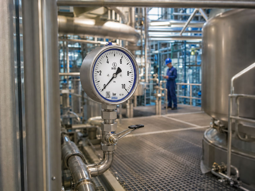
A pressure gauge is installed directly on a pressure line and is regularly read by operating personnel. Under normal operating conditions, the measuring point may appear completely uncritical. However, if the measuring system ruptures due to overpressure, a pressure surge, material fatigue or another fault, a considerable amount of energy can be released within a very short time.
With a conventional pressure gauge, under unfavorable circumstances:
- process medium,
- parts of the measuring system,
- housing components,
- or the window
can be expelled toward the operator.
This is exactly where the S3 safety version comes into play. It combines a non-splintering window, a solid rupture-resistant partition between the measuring system and the dial, and a blow-out back.
In the event of a failure, the pressure is deliberately relieved toward the rear. The front side, where operating personnel are typically positioned, remains protected by the solid-front partition.
A suitable example is the WIKA Safety Pressure Gauge Model 232.30 or 233.30. Both devices are manufactured in safety version S3 in accordance with EN 837-1. Model 233.30 additionally features case filling for applications with high dynamic pressure loads or vibration.
Further solutions can be found under Pressure Measurement Technology at ICS Schneider.
Table of Contents
- What does safety version S3 mean?
- How does an S3 pressure gauge protect the operator?
- Distinguishing between rupture wall, solid front and blow-out back
- S1, S2 and S3 compared
- When should an S3 pressure gauge be used?
- Why gaseous media are particularly critical
- Correctly assessing hazardous media
- Considering blow-out direction during installation
- Maintaining clearance behind the pressure gauge
- S3 pressure gauges in panels and operating areas
- S3 does not replace overpressure protection
- When case filling is useful
- Selecting the correct measuring range
- Checking material and process-medium compatibility
- Practical example: gas line in an operating area
- Typical selection and installation errors
- Systematically selecting a safety pressure gauge
- Suitable safety pressure gauges from ICS Schneider
- Conclusion
- FAQ
What does safety version S3 mean?
The safety version of a pressure gauge does not describe its measurement accuracy, but rather design measures intended to protect people in the event of a failure.
For a pressure gauge of safety level S3, these include in particular:
- a non-splintering or otherwise safely designed window,
- a rupture-resistant partition between the measuring system and the dial,
- a blow-out back.
The partition is often referred to as:
Solid front
.
The protection principle
If, for example, the Bourdon tube fails, the released energy should not escape toward the front through the window and dial.
Instead, the pressure relief is structurally directed toward the rear.
This particularly protects the person standing in front of the pressure gauge to read the measured value.
How does an S3 pressure gauge protect the operator?
A Bourdon tube pressure gauge contains a pressure-loaded elastic measuring element.
During normal operation, the Bourdon tube deforms depending on the process pressure. This movement is transmitted to the pointer via a mechanical movement.
In the event of a failure, however, for example:
Bourdon tube → measuring system → inside of the case
may become exposed to process pressure.
In an S3 version, a solid partition is located between the measuring system and the display
This separates:
- the dial,
- the pointer,
- the window,
- the operator side
from the actual pressure-loaded measuring system.
At the same time, the rear of the case is designed so that it can relieve pressure in a controlled manner in the event of a failure.
S3 therefore does not mean that the pressure gauge remains closed in the event of a failure. The safety function is specifically designed to direct the released energy in a defined direction away from the operator.
Distinguishing between rupture wall, solid front and blow-out back
In general usage, safety pressure gauges are often described as having a:
rupture wall
.
Technically, however, two different components should be distinguished.
Rupture-resistant partition – solid front
It is located between:
measuring system ↔ dial / window
and prevents parts of the measuring system from being expelled toward the front in the event of a failure.
Blow-out back
It is located at the rear of the case and provides the intended pressure-relief path.
In the event of a failure, it can open or blow out so that:
- pressure,
- process medium,
- and, where applicable, components
can escape toward the rear.
For a safe measuring point, both features are therefore essential: a stable front barrier and a clear pressure-relief path at the rear.
S1, S2 and S3 compared
| Safety level | Design principle | Personnel protection |
|---|---|---|
| S1 | Pressure-relief opening or blow-out device in the rear of the case | Pressure can be relieved toward the rear, but there is no solid separation between the measuring system and the front |
| S2 | Blow-out device or blow-out back | Enhanced pressure relief, but without a solid-front partition |
| S3 | Rupture-resistant partition + blow-out back + safely designed window | Highest safety level with controlled pressure relief toward the rear and protection of the front side |
The key difference between S1 and S3
An S1 version also has a rear pressure-relief option.
However, in the event of very rapid and high-energy damage to the measuring system, there is no solid-front partition structurally separating the operator side from the measuring system.
S3 therefore supplements rear pressure relief with a solid protective barrier toward the front.
When should an S3 pressure gauge be used?
The selection does not depend solely on the maximum process pressure.
Among other things, the following should be assessed:
- physical state of the process medium,
- operating pressure,
- stored energy,
- hazardous nature of the process medium,
- installation location,
- areas where people are present,
- possible pressure surges,
- process risk in the event of a measuring-system rupture.
S3 is particularly useful for measuring points requiring increased personnel protection
For example, if the pressure gauge:
- is located directly at eye level,
- is installed at an operator station,
- is regularly read manually,
- is installed in a walk-in plant area,
- measures a compressible or hazardous medium.
Why gaseous media are particularly critical
The difference between liquids and gases is particularly important for the safety assessment.
Under normal conditions, liquids are only very slightly compressible.
Gases, on the other hand, store considerably more expansion energy when pressurized.
In the event of a sudden rupture
a compressed gas can expand very rapidly.
This can place significantly greater stress on the pressure-gauge case than in a comparable liquid application.
With reference to EN 837-2, WIKA points to the use of safety version S3 for gaseous or vaporous process media from an operating pressure of approximately:
25 bar
.
However, pressure alone is not sufficient
An S3 version can also be useful below this range, for example with:
- flammable gases,
- toxic gases,
- hydrogen,
- strongly pulsating gas lines,
- measuring points located directly in operating areas.
The specific risk assessment of the system remains decisive.
Correctly assessing hazardous media
An S3 case improves personnel protection in the event of mechanical failure.
However, it does not automatically make a pressure gauge suitable for every hazardous process medium.
For hazardous media, the following must additionally be checked
- chemical resistance of the wetted materials,
- sealing materials,
- process connection,
- permissible temperature,
- required leak tightness,
- cleanliness requirements,
- explosion protection, if required,
- applicable application-specific regulations.
Oxygen
For oxygen applications, S3 alone is not sufficient.
The measuring instrument must additionally be suitable for oxygen and be designed accordingly:
oil- and grease-free
.
Hydrogen
For hydrogen, material compatibility and leak tightness must also be considered. For corresponding applications, WIKA recommends, among other options, the safety version of models 232.30 and 233.30.
Flammable or toxic media
Here, particular attention must be paid to where the process medium would go in the event of rear pressure relief.
An S3 pressure gauge protects the person from direct discharge toward the front. However, it does not fundamentally prevent process medium from escaping from the device in the event of a failure.
The rear blow-out zone must therefore also be included in the overall system safety assessment.
Considering blow-out direction during installation
The safety function of an S3 pressure gauge can only work properly if the rear side can actually be used as a pressure-relief path.
An unfavorable installation would be, for example
to mount the pressure gauge so that directly behind the blow-out back there is:
- a solid wall,
- a pipe,
- a control-cabinet component,
- a cable tray.
This could obstruct the intended pressure relief.
Even more critical
is an installation in which people regularly remain behind the pressure gauge.
With an S3 pressure gauge, the intended hazard zone is deliberately shifted from the front to the rear.
This blow-out direction must therefore already be considered when planning the measuring point.
Maintaining clearance behind the pressure gauge
For pressure gauges with a blow-out back or pressure-relief device, sufficient clearance must be provided behind the case.
In corresponding operating instructions, WIKA specifies a minimum distance of:
20 mm
from objects behind the pressure-relief device.
This value is not a general substitute for the manufacturer’s instructions
For the specific device version, always check the:
- data sheet,
- operating instructions,
- approvals
of the actual pressure gauge used.
In safety-critical applications, the blow-out zone should also be designed so that any escaping medium does not create a new hazard.
S3 pressure gauges in panels and operating areas
The S3 function must be considered particularly carefully when the pressure gauge is installed in a panel.
From the front, the installation appears ideal
Operating personnel only see:
- the dial,
- the pointer,
- the safely designed window.
The hazardous side is located behind the panel.
However, sufficient space must be available there
The blow-out back must not:
- rest directly against a mounting plate,
- be obstructed by electronic components,
- blow out toward a cable tray,
- relieve pressure into an area that is regularly occupied.
For toxic or flammable media, it may be necessary to arrange the entire measuring point differently or to separate the pressure gauge spatially from the actual pressure tapping point using a suitable measuring line.
S3 does not replace overpressure protection
A common selection error is to treat safety version and overload resistance as the same thing.
These are two different properties.
S3 describes
the behavior of the case in the event of a failure
Overload resistance describes
the pressure the measuring system can withstand without permanent damage
An S3 pressure gauge must therefore not automatically be exposed to any arbitrarily high pressure.
Additional protective measures may be required in the event of pressure peaks
For example:
- restrictor orifice,
- adjustable damping,
- overpressure protector,
- high-overload pressure gauge.
The S3 safety version is the final protective barrier for the failure case and is not a substitute for a properly designed pressure measuring point.
When case filling is useful
WIKA models 232.30 and 233.30 fundamentally use the same S3 safety principle.
The key difference is:
| Model | Version | Typical application |
|---|---|---|
| 232.30 | unfilled case | stable process conditions |
| 233.30 | liquid-filled case | vibration and dynamic pressure loads |
Case filling particularly damps
- pointer oscillations,
- mechanical vibrations,
- stress on the movement.
This improves readability under unstable plant conditions and reduces mechanical stress on the indicator.
However, case filling does not damp extreme process pressure peaks acting on the actual measuring element. In the event of strong pulsations, an additional restrictor or pulsation damper may be required.
Selecting the correct measuring range
An S3 pressure gauge must also be sized to match the actual operating pressure.
For good readability and sufficient reserve, the normal operating pressure should not remain permanently at the full-scale value.
As a proven guideline
the normal operating pressure should preferably lie in the middle range of the scale.
Example:
Operating pressure approx. 6 bar → measuring range 0 … 10 bar
may, depending on the process, be more suitable than:
measuring range 0 … 6 bar
if pressure fluctuations occur close to 6 bar.
With pulsating pressures
the permissible dynamic load must also be taken into account.
An incorrectly selected measuring range increases the probability of:
- permanent deformation of the Bourdon tube,
- zero-point shift,
- premature wear,
- failure of the measuring system.
Checking material and process-medium compatibility
The S3 safety version does not by itself indicate whether the process medium is chemically compatible with the measuring system.
For WIKA models 232.30 and 233.30, the measuring element is made of stainless steel as standard.
This is suitable for many:
- gaseous,
- liquid,
- aggressive
process media, provided they are not highly viscous or crystallizing and the specific material compatibility is ensured.
A diaphragm seal may be required for critical process media
For example with:
- highly viscous media,
- crystallizing media,
- heavily contaminated media,
- very hot media,
- media that must not enter the Bourdon tube.
In such cases, the pressure gauge is separated from the process medium by a suitable diaphragm seal.
Practical example: gas line in an operating area
The pressure of a gas line in a process plant is to be monitored.
The measuring point is located at a height of approximately:
1.6 m
and is checked daily by operating personnel.
The operating pressure is:
40 bar
Unsuitable selection
A conventional process pressure gauge with a simple rear pressure-relief opening is installed directly at eye level.
In the unlikely event of a sudden measuring-system rupture, the operator is positioned directly in front of the window.
Better solution
An:
S3 safety pressure gauge
is used with:
- solid-front partition,
- non-splintering window,
- blow-out back.
The pressure gauge is installed so that sufficient free space is available behind the rear of the case and the rear area is not used as an operating or traffic zone.
In addition, the following are checked:
- measuring range,
- material compatibility,
- overpressure load,
- pulsations,
- hazardous properties of the process medium.
Only the combination of a suitable pressure gauge and a correct installation situation results in a safe measuring point.
Typical selection and installation errors
| Observation / selection | Problem | Recommended action |
|---|---|---|
| Standard pressure gauge on a high-pressure gas line | insufficient personnel protection | Check safety level and use S3 where appropriate |
| Blow-out back directly in front of a wall | pressure relief obstructed | Provide the required rear clearance |
| People regularly remain behind the pressure gauge | blow-out direction points into an occupied area | Change installation location or orientation |
| S3 is treated as overpressure protection | measuring system can still be overloaded | Design measuring range and overpressure protection separately |
| Pressure gauge vibrates strongly | movement and indication are subjected to stress | Check liquid-filled version or mechanical isolation |
| Hazardous process medium approved solely because of S3 | material or process risks not assessed | Check process-medium compatibility and regulations separately |
| Oxygen used with a standard version | cleanliness requirements not met | Use an oil- and grease-free oxygen version |
| Strong pressure surges despite S3 | Bourdon tube is mechanically overloaded | Provide restrictor, damper or overpressure protection |
| Liquid-filled pressure gauge considered sufficient for pulsating process pressure | case filling primarily damps the movement | Additionally reduce process pulsations |
| Pressure gauge installed directly in operating area, rear side inside control cabinet | blow-out zone may be obstructed | Check control-cabinet arrangement and rear clearance |
Systematically selecting a safety pressure gauge
- Determine the process medium: Clearly identify whether it is a liquid, gas or vapor.
- Assess the hazard: Consider flammability, toxicity, reactivity and special cleanliness requirements.
- Determine the operating pressure: Record normal pressure, maximum operating values and possible pressure peaks.
- Assess personnel exposure: Is the measuring point located in an operating or traffic area?
- Define the safety level: Consider requirements according to EN 837 and the system risk assessment.
- Check S3 where increased personnel protection is required: Particularly with compressible and hazardous process media.
- Select the measuring range: Do not operate continuously at the full-scale pressure.
- Check materials: Measuring system, connection and, where applicable, seals must be compatible with the process medium.
- Assess overpressure: Do not confuse safety version with overload protection.
- Assess pulsations: Provide restriction or damping where necessary.
- Consider vibrations: Select a liquid-filled version if required.
- Plan the blow-out direction: Do not orient the rear toward operators or sensitive components.
- Maintain clearance: Observe the manufacturer’s requirements for the blow-out back.
- Check installation position: The solid front only provides meaningful protection if the intended pressure-relief direction remains unobstructed.
- Check special approvals: For example ATEX, oxygen version or other application-specific requirements.
Suitable safety pressure gauges from ICS Schneider
WIKA Model 232.30 – Safety Pressure Gauge without Case Filling
The WIKA Model 232.30 is a stainless-steel Bourdon tube pressure gauge for increased safety requirements in the process industry.
Key features include:
- safety version S3,
- rupture-resistant solid-front partition,
- blow-out back,
- non-splintering window,
- stainless-steel version,
- scale ranges from 0 … 0.6 to 0 … 1,600 bar.
The device is suitable for many liquid and gaseous, including aggressive, process media, provided material compatibility and the other process conditions are met.
WIKA Model 233.30 – Safety Pressure Gauge with Case Filling
The WIKA Model 233.30 additionally features liquid case filling.
This version is particularly suitable for:
- mechanical vibrations,
- unstable pointer indication,
- dynamic pressure loads.
Further options
Depending on the configuration, versions are available for special applications including:
- oxygen, oil- and grease-free,
- hazardous areas,
- special materials,
- increased leak-tightness requirements.
Further pressure gauges can be found under Pressure Measurement Technology at ICS Schneider.
Conclusion
With an S3 safety pressure gauge, the main focus is not higher measurement accuracy, but personnel protection in the event of a failure.
S3 combines several protective measures
A rupture-resistant solid-front partition protects the operator side, while a blow-out back directs pressure, process medium and, where applicable, components toward the rear.
The blow-out direction is part of the safety function
An S3 pressure gauge must therefore not be installed with an obstructed rear side or immediately in front of an occupied area.
S3 becomes particularly important for gases
Compressed gases store significantly more expansion energy than liquids. At higher pressures and in operating areas, personnel protection must therefore be assessed particularly carefully.
Hazardous process media require additional checks
S3 does not replace material compatibility, oxygen cleanliness, explosion protection or other application-specific requirements.
S3 is also not an overpressure protector
Pressure peaks and pulsations must still be controlled through suitable measuring-range selection or additional protective components.
For practical applications
Determine process medium and operating pressure → assess hazard and operating area → select the appropriate safety level → check S3 where increased personnel protection is required → design measuring range and overload protection separately → check materials and approvals → consider vibration and pulsation → keep the blow-out back unobstructed → direct the blow-out away from operating personnel → observe the manufacturer’s requirements for rear clearance.
FAQ: Selecting S3 Safety Pressure Gauges Correctly
What does S3 mean on a pressure gauge?
S3 designates a safety version with a rupture-resistant partition between the measuring system and the dial as well as a blow-out back. This protects operating personnel on the front side in the event of a failure.
What is a solid-front design?
Solid front refers to the solid partition between the pressure-loaded measuring system and the front side of the pressure gauge.
What is the rupture wall on a safety pressure gauge?
The term is used differently in general language. With an S3 version, a distinction should be made between the rupture-resistant solid-front partition and the blow-out back of the case.
What happens if the Bourdon tube of an S3 pressure gauge ruptures?
The solid-front partition protects the front side. Pressure, process medium and possible components are intended to escape through the designated rear side of the case.
What is the difference between S1 and S3?
S1 provides a rear pressure-relief option. S3 additionally has a solid partition between the measuring system and the operator side and therefore offers a higher level of personnel protection.
When is S3 useful for gaseous media?
With gaseous and vaporous process media, the risk increases due to stored expansion energy. With reference to EN 837-2, WIKA particularly points to S3 from an operating pressure of approximately 25 bar. However, the specific risk assessment remains decisive.
Does this mean I never need S3 below 25 bar?
No. For hazardous gases, hydrogen, toxic media or measuring points located directly in operating areas, S3 can also be useful or required at lower pressures due to other requirements.
Is an S3 pressure gauge automatically resistant to overpressure?
No. S3 describes the safety behavior of the case in the event of a failure. The permissible overload of the measuring system is a separate technical property.
Does S3 protect against pressure surges?
S3 protects personnel in the event of possible instrument failure. Pressure surges should nevertheless be limited using suitable restrictors, dampers or overpressure protection devices.
Why must there be space behind an S3 pressure gauge?
The rear of the case is the intended pressure-relief path. If it is obstructed, the safety function may be impaired.
How much space must remain behind the blow-out back?
In corresponding operating instructions, WIKA specifies at least 20 mm clearance from objects. The operating instructions for the specific version are always decisive.
Can there be a wall behind the pressure gauge?
Only if the required clearance for pressure relief is maintained and the blow-out function is not obstructed.
Can an S3 pressure gauge be installed in a panel?
Yes, provided the rear blow-out zone remains sufficiently clear and the pressure relief is not obstructed by mounting plates, cable ducts or other components.
Is an S3 pressure gauge automatically suitable for flammable gases?
No. Material compatibility, leak tightness, explosion protection where required, and other application-specific requirements must also be checked.
Is an S3 pressure gauge automatically suitable for oxygen?
No. Oxygen applications additionally require specially cleaned, oil- and grease-free versions.
Which S3 pressure gauge is suitable for vibration?
WIKA Model 233.30 has case filling and is therefore particularly suitable for measuring points with mechanical vibration and dynamic pressure loads.
What is the difference between WIKA 232.30 and 233.30?
Model 232.30 has an unfilled case. Model 233.30 is available with liquid case filling, which damps pointer movement under vibration.
Which measuring ranges are available for WIKA 232.30 and 233.30?
Depending on the version, scale ranges from 0 … 0.6 to 0 … 1,600 bar are available.
Where can I find the WIKA safety pressure gauge at ICS Schneider?
Further information is available under WIKA Models 232.30 and 233.30 at ICS Schneider.
Where can I find further pressure measuring instruments?
An overview is available under Pressure Measurement Technology at ICS Schneider.