


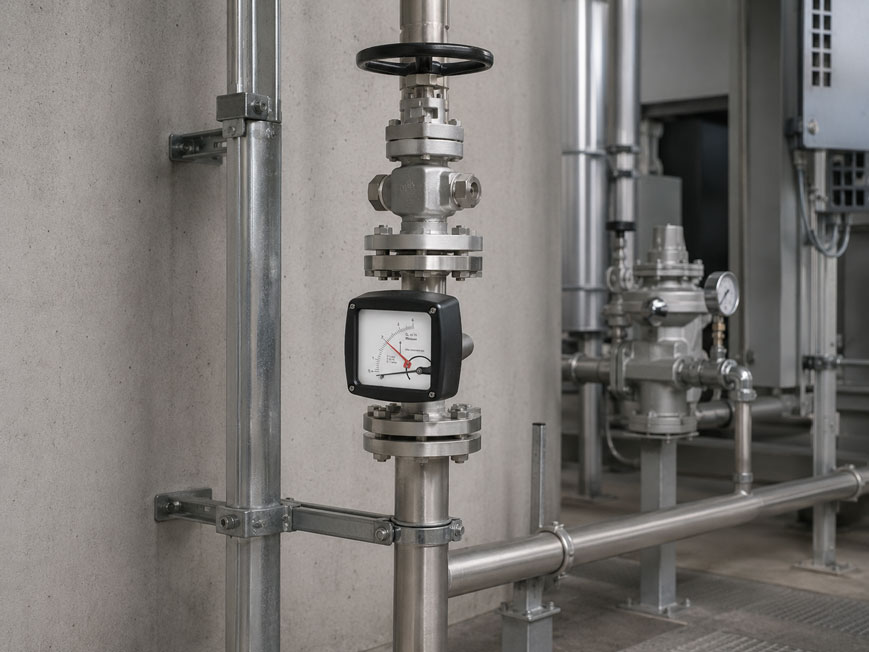
A variable-area flowmeter shows a stable flow rate in the test setup. After installation in the system, however, the pointer begins to fluctuate, the measured value deviates significantly from the expected flow rate, or the float strikes the upper stop when a valve is opened.
This does not necessarily mean that the measuring device is defective. With the variable-area measuring principle, the hydraulic or pneumatic operating conditions directly influence the position of the float.
Particularly important are:
- correct installation position,
- flow direction,
- operating pressure and back pressure,
- position of throttling and control valves,
- pulsations and pressure surges,
- controlled start-up of the measuring point.
A standard variable-area flowmeter must be installed according to its design. For a device designed for vertical operation, this usually means vertical installation with flow from bottom to top. Particularly with gases, the operating pressure and valve position must also be taken into account because changes in gas density can directly affect the indication.
A suitable example from the ICS portfolio is the Siemens SITRANS FVA250 Variable-Area Flowmeter. This robust all-metal device is designed for liquids and gases in closed pipelines and is installed vertically with flow from bottom to top. Further devices can be found under Variable-Area Flowmeters and under Flow Measurement Technology at ICS Schneider.
Table of Contents
- How a variable-area flowmeter works
- Why the vertical installation position is crucial
- Why the flow direction is from bottom to top
- What happens if the device is installed at an angle?
- Why operating pressure is particularly important for gases
- Considering back pressure correctly
- Where should the control valve be installed?
- Minimum operating pressure and pressure loss
- Why pulsating flow affects the float
- Typical causes of pulsations
- When damping is useful
- Starting up the measuring point slowly
- Special considerations for liquids
- Special considerations for gases
- Consider scaling and operating conditions
- Inlet and outlet conditions
- Avoid mechanical vibrations
- Typical error patterns
- Practical example: fluctuating indication in a gas line
- Systematically installing a variable-area flowmeter
- Suitable flow measurement technology from ICS Schneider
- Conclusion
- FAQ
How a variable-area flowmeter works
In a variable-area flowmeter, a movable float is located in a flow cross-section that increases toward the top.
The medium flows around the float and lifts it upward.
The main forces acting on the float are
- gravitational force,
- buoyancy,
- flow force.
As the flow rate increases, the float rises.
This increases the free flow cross-section between the float and the measuring tube or measuring ring.
The float settles at an equilibrium height
This position corresponds to a defined flow rate.
With a classic transparent rotameter, the position is read directly from a scale.
With an all-metal device such as the:
SITRANS FVA250
the movement of the float is transmitted magnetically to the external indicator.
Since gravitational force is part of this force equilibrium, the installation position is an inherent part of the measuring principle in a classic variable-area flowmeter.
Why the vertical installation position is crucial
In a variable-area flowmeter designed for vertical operation, gravity acts downward along the measuring axis.
The flow acts in the opposite direction.
This creates the intended force equilibrium.
The standard configuration is:
vertical pipeline + flow from bottom to top
For the Siemens SITRANS FVA250, this installation position is explicitly specified
The device is operated:
vertically / from bottom to top
.
This ensures that the actual measuring conditions correspond to the design and scaling of the device.
Horizontal installation is not automatically permissible
There are special variable-area flowmeters that are designed for other installation positions.
The installation position must therefore not be derived from the measuring principle alone.
The installation and flow direction approved for the specific device is always decisive.
Why the flow direction is from bottom to top
At zero flow, the float is located at the lower end of its operating range.
When the medium begins to flow from bottom to top, an upward force is generated.
The float rises until:
flow force + buoyancy = effective gravitational force
is reached.
If a device designed for this operating principle were flowed through from top to bottom
the flow would no longer act against gravity as intended.
The correct relationship between:
float position ↔ flow rate
would no longer be maintained.
For this reason, the pipeline design should already clearly define the position of:
- inlet,
- measuring device,
- outlet,
- shut-off or control valve.
What happens if the device is installed at an angle?
Even a slightly tilted variable-area flowmeter can cause problems.
The float or its guide may then
- be subjected to lateral loads,
- rub against the guide,
- no longer respond freely,
- show additional hysteresis.
As a result, the indicated value may depend on whether the flow rate is currently:
increasing
or:
decreasing
.
Before installation, therefore, the following should be checked
- pipeline actually vertical,
- flanges correctly aligned,
- measuring device installed without mechanical stress,
- no lateral force caused by a misaligned pipeline.
The pipeline must not mechanically pull the measuring device into an incorrect position.
Why operating pressure is particularly important for gases
With liquids, density changes relatively little under normal pressure variations.
With gases, this is different.
If the absolute pressure of a gas increases, its density also increases under otherwise comparable conditions.
This directly affects the force equilibrium of the float
A scale designed for:
air at a defined pressure and temperature
cannot therefore simply be transferred to significantly different operating conditions.
Particularly relevant are:
- type of gas,
- absolute operating pressure,
- temperature,
- desired unit or reference conditions.
For a gas application, it must therefore be clarified during design
whether the scale is intended to indicate the flow rate at:
- actual operating conditions,
- standard conditions,
- other defined reference conditions.
The specification “10 m³/h air” is therefore often insufficient for a reliable design of a variable-area flowmeter.
Considering back pressure correctly
Back pressure is, in simplified terms, the pressure present on the outlet side of the flowmeter.
Particularly with gases, this pressure affects the gas density inside the measuring device.
Example
A variable-area flowmeter is scaled for a specific gas pressure.
However, downstream of the device there is:
- a control valve,
- a long pipeline,
- a filter,
- a downstream process
with a defined back pressure.
The actual pressure inside the measuring device may therefore be significantly above atmospheric pressure.
This is not necessarily a problem
The decisive point is:
The actual pressure in the measuring device must correspond to the operating conditions for which the scale or device configuration was designed.
If the back pressure is changed significantly later, a previously correct flow indication must not be assumed to remain valid without verification.
Where should the control valve be installed?
The position of a throttling or control valve is particularly important for gases.
For gas applications with the SITRANS FVA250
valves should be installed on the:
outlet side of the flowmeter
.
For measurements designed for an elevated absolute pressure, the control valve is also generally installed downstream of the variable-area flowmeter.
Why?
The downstream valve keeps the pressure inside the measuring device comparatively well defined.
If throttling were performed exclusively upstream of the flowmeter and its outlet discharged practically freely to atmosphere, different pressure conditions would exist inside the device.
With gases, this can affect density and therefore the indication.
Compression oscillations can also occur
For gas measurement, Siemens therefore recommends a throttle directly downstream of the measuring device if compression oscillations need to be avoided.
The valve position in a gas flow measurement should therefore not be selected solely according to the most convenient pipeline location.
Minimum operating pressure and pressure loss
A variable-area flowmeter also causes a pressure loss.
The process must have sufficient pressure reserve so that the required flow can pass stably through the measuring device.
For the SITRANS FVA250, Siemens specifies the following condition
minimum operating pressure > 2 × pressure loss of the measuring device
The actual pressure loss depends, among other things, on:
- nominal diameter,
- measuring range,
- medium,
- float design.
If the pressure reserve is too low
the flow rate can react sensitively to:
- valve movements,
- pressure changes in the process,
- compressor cycles,
- downstream consumers.
An apparently unstable flowmeter can therefore also indicate unstable hydraulic or pneumatic conditions in the system.
Why pulsating flow affects the float
The measuring principle requires a sufficiently stable flow.
If the volumetric flow rate changes continuously, the float follows these changes.
The indication begins:
to oscillate or vibrate
With slow fluctuations
the movement may still represent the actual process behavior.
With rapid pulsations
the float may:
- be continuously accelerated,
- strike against its guide,
- fail to reach a stable reading position,
- be subjected to increased mechanical stress.
Simply averaging the indication visually is not a technically clean solution.
Typical causes of pulsations
Pulsating flow can be caused by various system components.
Typical causes include
- piston pumps,
- diaphragm pumps,
- metering pumps,
- reciprocating compressors,
- fast-switching solenoid valves,
- unstable pressure regulators,
- periodically operating consumers.
The control system itself can also generate pulsation
If, for example, a valve continuously oscillates between:
too far open ↔ too far closed
the flow follows this control behavior.
The float then simply makes the instability of the process visible.
When damping is useful
For unstable operating conditions, variable-area flowmeters can be equipped with mechanical or design-based damping.
For the SITRANS FVA250, Siemens recommends damping, among other cases
- generally for gas measurements,
- when air bubbles in the medium cannot be avoided,
- in the event of pressure surges,
- with turbulent or pulsating flow,
- when pipeline vibrations cannot be avoided,
- when the operating pressure cannot be built up slowly.
However, damping only addresses the behavior of the measuring device
A strongly pulsating process flow should preferably be stabilized at its source.
Depending on the application, suitable measures may include:
- pulsation dampers,
- pressure accumulators,
- suitable throttles,
- more stable pressure regulation,
- adapted pump control.
A mechanical damper on the float does not replace fundamentally stable process conditions.
Starting up the measuring point slowly
Start-up is a critical moment for a variable-area flowmeter.
If the pipeline is depressurized and an upstream valve is suddenly opened completely, the float can be accelerated sharply.
The result may be
the float strikes the upper stop
.
This places stress on:
- float,
- guide,
- damping system,
- mechanical indication transmission.
For the SITRANS FVA250, Siemens recommends
starting commissioning with the shut-off valve closed and then:
opening it slowly
.
Fast-switching solenoid valves are unfavorable for this procedure.
For liquids
the pipeline should be vented and filled slowly.
For gases
the pressure should be built up slowly and in a controlled manner.
This reduces pressure surges and abrupt float movements.
Special considerations for liquids
For liquids, the following points are particularly relevant:
- fully filled measuring section,
- no significant gas bubbles,
- sufficient operating pressure,
- appropriate density and viscosity,
- stable flow.
Gas bubbles can destabilize the indication
They temporarily change:
- density,
- flow conditions,
- buoyancy acting on the float.
The pipeline should therefore be carefully vented during commissioning.
Viscosity is also relevant
A scale designed, for example, for water must not be used for a significantly more viscous oil without verification.
The flow conditions around the float change, and therefore so does the relationship between float position and flow rate.
Special considerations for gases
Additional influencing factors apply to gases.
Particularly important are
- type of gas,
- temperature,
- absolute pressure in the measuring device,
- back pressure,
- compressibility,
- pulsations.
Specifying gauge pressure alone may not be sufficient for correct sizing.
For gas density, the:
absolute pressure
is decisive.
Example
A system operates at:
2 bar gauge pressure
At normal atmospheric pressure, the absolute pressure is therefore approximately:
3 bar absolute
and not:
2 bar absolute
.
This distinction is crucial when sizing and scaling a variable-area flowmeter.
Consider scaling and operating conditions
A variable-area flowmeter is not a purely geometric volumetric display.
Its scaling depends on the medium properties and operating conditions.
For correct sizing, at least the following should be known
- medium,
- required measuring range,
- density,
- viscosity for liquids,
- operating pressure for gases,
- operating temperature,
- required flow unit,
- reference conditions for gases.
If the medium is later changed
for example from:
water → glycol mixture
or:
air → nitrogen
it must be checked whether the existing scale can still be used.
If the operating conditions change significantly, a new sizing or scale is the technically cleaner solution.
Inlet and outlet conditions
Variable-area flowmeters often do not require straight inlet lengths as long as those required by some other flow measurement principles.
However, this does not mean that the flow immediately upstream of the device may be arbitrarily disturbed.
For the SITRANS FVA250, in particular
- strongly one-sided restrictions immediately upstream of the device should be avoided,
- pipeline and device nominal diameters should match,
- strongly asymmetrical flow profiles should be stabilized where necessary.
With a strongly asymmetrical flow profile
additional measures such as:
- a straight inlet section,
- a flow straightener
may be useful.
For the FVA250, Siemens specifies, where an inlet section is required, at least the device length of:
250 mm
.
Avoid mechanical vibrations
Not every vibration of the float is caused by pulsating flow.
The pipeline itself may also vibrate mechanically.
Possible sources include
- pumps,
- compressors,
- motors,
- poorly supported pipelines.
The pipeline should therefore be sufficiently and securely supported.
The measuring device itself should
- be installed without mechanical stress,
- not be used as a pipe support,
- not be stressed by flange misalignment.
For indicators using magnetic transmission, the manufacturer’s specified distances from magnetic or ferromagnetic components must also be observed.
Typical error patterns
| Observation | Possible cause | Recommended check |
|---|---|---|
| Float remains at the bottom | Incorrect flow direction or flow rate too low | Check installation direction and measuring range |
| Indication permanently too high or too low | Medium or operating conditions differ from scaling conditions | Check density, temperature and pressure |
| Indication fluctuates continuously | Pulsating flow | Check pump, compressor and valves |
| Float strikes upward during start-up | Valve opened too quickly | Perform controlled commissioning |
| Gas indication strongly pressure-dependent | Gas density or back pressure has changed | Check absolute pressure in the measuring device |
| Pointer oscillates at a constant setpoint | Compression oscillation or unstable control | Check throttle position and damping |
| Measured value changes after valve modification | Pressure conditions in the measuring device have changed | Compare valve position and calibration conditions |
| Float moves jerkily | Friction, contamination or tilted installation | Check free movement and alignment |
| Indication changes with pipeline vibration | Mechanical vibration | Check pipeline supports and damping |
| Liquid measurement is unstable | Gas bubbles in the medium | Vent the pipeline |
| Device works well at higher flow but poorly at low flow | Measuring range selected unfavorably or float not stable | Check sizing and operating range |
Practical example: fluctuating indication in a gas line
In a system, the air flow to a process is to be monitored.
An all-metal variable-area flowmeter is used.
The initial setup
consists of:
compressed-air network → solenoid valve → flowmeter → consumer
When switched on, the solenoid valve opens abruptly.
The float:
- jumps upward,
- then oscillates strongly,
- does not provide a stable readable value.
In addition, the consumer pressure fluctuates
This also changes the pressure at the outlet of the flowmeter.
The flowmeter is initially incorrectly assumed to be unstable.
Improved setup
The measuring point is designed so that:
- the flowmeter is mounted vertically and without mechanical stress,
- the flow direction is from bottom to top,
- the pressure is built up slowly,
- a suitable throttle or control valve is installed on the outlet side,
- the pressure in the measuring device corresponds to the intended scaling conditions,
- strong pulsations are damped where necessary.
After these changes, the indication becomes significantly more stable.
This example shows that the measurement quality of a variable-area flowmeter depends not only on the sensor itself. The pressure and flow conditions of the entire measuring point are part of the design.
Systematically installing a variable-area flowmeter
- Define the medium: Determine whether the medium is a liquid or gas and specify its properties.
- Define the measuring range: Consider normal operating flow and possible peaks.
- Specify operating data: Record pressure, temperature, density and, for liquids, viscosity.
- Check scaling: Ensure that device and scale match the medium and operating conditions.
- Check installation position: Follow the specification of the specific device.
- Install the FVA250 vertically: Flow direction from bottom to top.
- Align the pipeline: Install the measuring device without mechanical stress between the connections.
- Support the pipeline sufficiently: Avoid mechanical vibrations.
- Check flow disturbances: Avoid one-sided restrictions directly upstream of the device.
- Define valve position: For gases, follow the manufacturer’s specification for the downstream valve.
- Consider back pressure: Compare the actual pressure in the measuring device with the design conditions.
- Check pressure loss: Ensure sufficient pressure reserve for the required flow.
- Assess pulsations: Consider pumps, compressors and fast-switching valves.
- Provide damping: If the process cannot provide sufficiently stable flow.
- Vent liquid lines: Avoid gas bubbles.
- Build up gas pressure slowly: Prevent pressure surges.
- Open shut-off valves slowly: Do not accelerate the float against the stop.
- Observe the indication: Watch for oscillation, friction or unusual pointer movement.
- Document operating conditions: Record pressure, temperature, medium and scaling.
Suitable flow measurement technology from ICS Schneider
Siemens SITRANS FVA250 Variable-Area Flowmeter
The SITRANS FVA250 is particularly suitable for this topic.
The device is an all-metal variable-area flowmeter for liquids and gases in closed pipelines.
Key features include:
- robust all-metal design,
- vertical installation with flow direction from bottom to top,
- suitable for high pressures and temperatures,
- various flange connections,
- different float and wetted-part materials,
- product or percentage scale,
- optional transmitter,
- optional limit switches,
- optional damping.
Accuracy
Depending on the medium, Siemens specifies a measuring accuracy for the SITRANS FVA250 of:
±1.6% for liquids
and:
±2.0% for gases
according to the specified device classification.
For demanding process applications
the device can also be integrated into process monitoring with:
- 4…20 mA transmitter,
- HART,
- limit switches.
Further versions can be found under Variable-Area Flowmeters at ICS Schneider.
When is another measuring principle more suitable?
A variable-area flowmeter is particularly useful for robust and directly visible flow indication.
For requirements such as:
- very large measuring dynamics,
- strongly pulsating flow,
- very high accuracy,
- bidirectional measurement,
- direct mass flow measurement
another measuring principle may be more suitable.
An overview of the available technologies can be found under Flow Measurement Technology at ICS Schneider.
Conclusion
Variable-area flowmeters are robust and comparatively simple measuring devices. Precisely for this reason, the influence of the installation conditions is often underestimated.
The installation position is part of the measuring principle
For a vertically designed device such as the SITRANS FVA250, installation is vertical and the flow direction is from bottom to top.
For gases, pressure is part of the measuring task
Gas density depends on the operating conditions. Therefore, scaling, actual pressure in the measuring device and back pressure must correspond to one another.
The valve position can be decisive
For gas measurements with the SITRANS FVA250, valves are installed on the outlet side. A throttle directly downstream of the device can also help reduce compression oscillations.
Pulsations cause unstable indication
Pumps, compressors and fast-switching valves can continuously accelerate the float. Where such influences cannot be avoided, suitable damping may be required.
Start-up must be controlled
Open valves slowly, vent liquid lines and build up gas pressure gradually. This helps prevent pressure surges and impacts of the float against its stop.
For practical applications
Determine medium and operating data → size and scale the device correctly → observe the specified installation position → install vertically and without mechanical stress → check flow direction → for gases, consider back pressure and valve position → ensure sufficient pressure reserve → avoid or damp pulsations and vibrations → vent liquid lines → build up gas pressure slowly → open valves slowly during commissioning → check the indication under actual operating conditions.
FAQ: Installing Variable-Area Flowmeters Correctly
How should a rotameter be installed?
A classic vertical variable-area flowmeter is installed vertically with flow from bottom to top. However, the installation specification of the specific device is always decisive.
Why must a variable-area flowmeter be installed vertically?
For a device designed for vertical installation, the gravitational force acting on the float is part of the measuring principle. It must act in the intended direction along the measuring axis.
Can a rotameter be installed horizontally?
Only if the specific device is designed for horizontal installation and approved accordingly by the manufacturer. A standard device designed for vertical operation must not simply be installed horizontally.
In which direction must the medium flow through the SITRANS FVA250?
The SITRANS FVA250 is installed vertically and the medium flows from bottom to top.
What happens if a rotameter is installed at an angle?
The float or its guide may be subjected to lateral loads. This can increase friction and hysteresis and affect the indication.
Why does pressure influence gas measurement?
Absolute pressure affects gas density. Since density and buoyancy are part of the float’s force equilibrium, pressure must be taken into account when scaling the device.
What does back pressure mean?
Back pressure is the pressure present on the outlet side of the flowmeter or in the downstream process.
Is back pressure equally important for liquids and gases?
The effect is particularly significant for gases because gas density changes considerably with pressure. Liquids are generally far less compressible.
Where should the control valve be installed for gas measurement with the FVA250?
Siemens specifies that valves for gas applications should be installed on the outlet side of the flowmeter. In suitable applications, a throttle directly downstream can also reduce compression oscillations.
Why should the valve not be opened abruptly?
A sudden increase in pressure or flow can strongly accelerate the float and cause it to strike its stop.
Are solenoid valves problematic during commissioning?
Fast-opening solenoid valves can cause strong pressure and flow surges. A slow pressure or flow build-up is preferable for controlled commissioning.
Why does the float fluctuate?
Typical causes include pulsating flow, pressure fluctuations, compression oscillations, gas bubbles, turbulence or mechanical pipeline vibrations.
Can a piston pump affect a rotameter?
Yes. Piston and diaphragm pumps often generate pulsating flow that the float may follow.
Can a compressor cause an unstable indication?
Yes. Reciprocating compressors and unstable pressure control in particular can generate pressure and flow pulsations.
What can help against pulsations?
Depending on the application, pulsation dampers, pressure accumulators, throttles, optimized control or damping integrated into the flowmeter can be used.
When does Siemens recommend damping for the FVA250?
Among other cases, for gas measurement, pressure surges, pulsations, turbulence, gas bubbles and unavoidable pipeline vibrations.
What happens if gas bubbles are present in a liquid?
Gas bubbles temporarily alter density, buoyancy and flow conditions. This can make the indication unstable or inaccurate.
Does a liquid line need to be vented before measurement?
Yes. During commissioning, the line should be filled and vented in a controlled manner to avoid pressure surges and gas bubbles.
Should gas pressure be built up slowly?
Yes. A slow pressure build-up reduces pressure surges and prevents abrupt acceleration of the float.
Does a variable-area flowmeter require straight inlet lengths?
Long straight inlet and outlet sections are often not required. However, strongly asymmetrical flow profiles or one-sided restrictions immediately upstream of the device should be avoided.
How long should the inlet section for the FVA250 be if required?
If an inlet section is required due to a strongly asymmetrical flow profile, Siemens specifies at least the device length of 250 mm.
Why must the pipeline be properly supported?
Mechanical vibrations can be transmitted to the measuring device and affect the movement of the float or pointer.
Can I use a variable-area flowmeter scaled for water with oil?
Not without verification. Density and, in particular, viscosity can change the relationship between float position and flow rate.
Can I use an air scale for nitrogen?
Only if the differences in medium properties and operating conditions have been properly taken into account. For accurate measurement, the device should be sized for the actual gas and operating conditions.
Which information is required for sizing a gas rotameter?
At least gas type, flow range, operating pressure, operating temperature, required unit and reference conditions should be known.
Which information is important for liquids?
Medium, flow range, density, viscosity, temperature, operating pressure and process connection are important design parameters.
What does minimum operating pressure mean for the FVA250?
Siemens specifies a minimum operating pressure greater than twice the device-specific pressure loss.
Can an oversized rotameter measure poorly?
Yes. If the normal flow rate is only in the very lower part of the scale, readability and usable resolution are reduced. The measuring range should therefore match the actual operating range.
Which ICS product is particularly suitable for this application?
The Siemens SITRANS FVA250 is a robust all-metal variable-area flowmeter for industrial liquid and gas applications.
Can the SITRANS FVA250 provide an electrical output signal?
Yes. The device can optionally be equipped with a transmitter and limit switches for process monitoring.
Where can I find further variable-area flowmeters?
An overview can be found under Variable-Area Flowmeters at ICS Schneider.
Where can I find further flowmeters?
Further measuring principles and devices can be found under Flow Measurement Technology at ICS Schneider.