


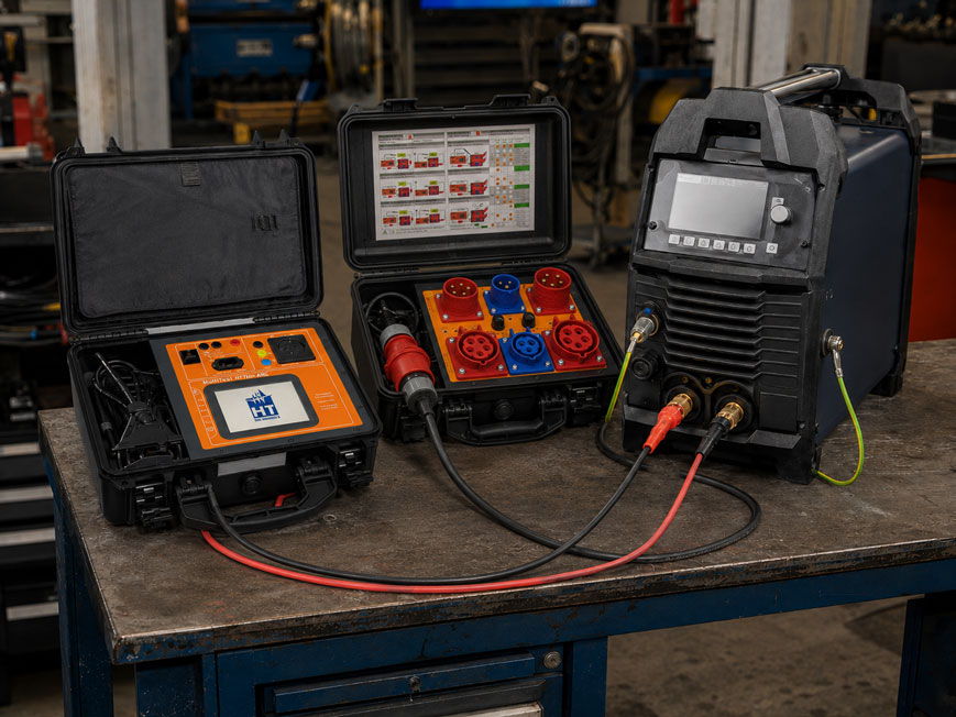
An arc welding machine is electrically significantly more complex than many conventional portable electrical appliances. In addition to the mains circuit, it has a galvanically isolated or power-electronically coupled welding circuit with high currents and a no-load voltage required for the welding arc.
For periodic testing, it is therefore not sufficient to simply check:
Protective conductor → insulation → function
as with a simple electrical appliance.
Among other things, the electrical safety of the welding circuit and the no-load voltage must also be assessed.
The current German standard is DIN EN IEC 60974-4:2025-12 or VDE 0544-4:2025-12. It replaces the previous DIN EN 60974-4:2017-05. The frequently used term “leakage current” is technically too imprecise: the standard distinguishes in particular between touch current of the welding circuit, touch current on accessible conductive parts and protective conductor current.
For this testing task, ICS Schneider offers, for example, the MultiTest HT700+ ARC. The appliance tester is specifically designed for testing arc welding equipment in accordance with DIN VDE 0544-4 or EN 60974-4 and, in addition to protective conductor, insulation and current measurements, also supports the required welding equipment tests.
Further test instruments can be found under Electrical Measuring and Test Equipment at ICS Schneider.
Table of Contents
- Which standard currently applies to welding equipment testing?
- Why welding equipment requires special testing
- Which tests are included in DIN EN IEC 60974-4?
- Do not underestimate the visual inspection
- Measuring protective conductor resistance correctly
- Testing insulation resistance between the primary and welding circuits
- Consider inverter welding machines during insulation testing
- Measuring the touch current of the welding circuit
- Testing the touch current of accessible parts
- Assessing protective conductor current correctly
- Why no-load voltage requires a separate test
- Assessing no-load voltage correctly
- Why a standard multimeter is not sufficient
- Do not confuse the primary and secondary sides
- Testing three-phase welding machines
- Functional test after the electrical measurements
- Recommended test sequence
- Practical example: 400 V inverter welding machine
- Typical fault patterns
- Documenting the test
- Why a dedicated welding equipment tester is useful
- Suitable test equipment from ICS Schneider
- Conclusion
- FAQ
Which standard currently applies to welding equipment testing?
The current standard for periodic testing of electrical arc welding equipment is:
DIN EN IEC 60974-4:2025-12 / VDE 0544-4:2025-12
The standard describes test procedures for:
- periodic testing,
- testing after repairs,
- testing as part of maintenance.
It applies in particular to power sources for arc welding and allied processes.
The 2025 edition replaces the 2017 edition
Compared with the previous edition, changes include:
- closer alignment of measurement methods with the IEC 61557 series of standards,
- expanded assessment of older welding power sources,
- consideration of battery-powered welding power sources.
Important for older technical literature
Older documents frequently use the term:
Leakage current
The current terminology distinguishes more precisely between:
- touch current of the welding circuit,
- touch current of accessible conductive surfaces,
- protective conductor current.
Although “leakage current” is still frequently used in search queries and everyday workshop practice, the correct measured quantity should preferably be stated in the test report.
Why welding equipment requires special testing
A typical arc welding machine has at least two electrically relevant areas:
Mains circuit → power electronics / transformer → welding circuit
On the mains side, for example:
- 230 V AC,
- 400 V AC three-phase
may be present.
On the output side, however, very high welding currents are generated.
The voltage is comparatively low during welding, but in no-load operation a sufficiently high voltage must be available to ignite or maintain the welding arc.
This is exactly what makes the testing task special
It must be ensured that:
- the protective conductor functions reliably,
- the mains and welding circuits are adequately insulated,
- no impermissible currents flow through welding leads or accessible parts,
- the no-load voltage remains within the permissible limits.
A welding machine may have a perfectly functioning protective conductor and still be electrically unsafe due to inadequate separation between the mains and welding circuits.
Which tests are included in DIN EN IEC 60974-4?
The exact scope of testing depends on the design, protection class and condition of the equipment.
Typical tests include:
- visual inspection,
- continuity of the protective conductor circuit,
- insulation resistance,
- touch current of the welding circuit,
- touch current of accessible conductive parts,
- protective conductor current,
- no-load voltage,
- functional test,
- documentation.
Not every measurement is identical for every equipment configuration
For example, a Class II power source is assessed differently from a Class I device with a protective conductor.
Also:
- permanently connected equipment,
- three-phase equipment,
- battery-powered power sources,
- older welding machines
may require special test conditions.
Do not underestimate the visual inspection
The visual inspection is performed before the electrical measurements.
Its purpose is not merely to identify obvious housing damage.
Items to be checked include
- mains connection cable,
- mains plug or CEE plug,
- strain reliefs,
- housing,
- ventilation openings,
- electrode holder or torch,
- welding current cables,
- workpiece connection cable,
- connectors,
- controls,
- markings and nameplate.
Welding cables in particular are subjected to high mechanical stress
Typical damage includes:
- cut insulation,
- thermal damage,
- exposed strands,
- damaged connectors,
- loose contacts.
An electrical measurement can therefore appear normal even though a safety-relevant mechanical defect is already present.
Measuring protective conductor resistance correctly
For mains-powered Class I equipment, the continuity of the protective conductor circuit must be tested.
The measurement is taken between:
PE contact of the mains connection ↔ accessible conductive housing parts connected to PE
For a mains connection cable up to 5 m
the measured protective conductor resistance according to the current standard must generally not exceed:
0.3 Ω
.
For longer cables
the permissible value increases by:
0.1 Ω for each additional 7.5 m
up to a maximum value of:
1 Ω
Move the cable during the measurement
Mechanical movement of the connection cable during testing is particularly important.
The cable should especially be moved or bent in the areas of:
- the plug,
- strain relief,
- housing entry.
This allows intermittent protective conductor interruptions to be detected that may remain unnoticed during a static measurement.
Testing insulation resistance between the primary and welding circuits
Insulation testing is particularly important for welding machines because several electrically isolated circuits must be considered.
The current standard typically specifies the following minimum values
| Measurement | Minimum insulation resistance |
|---|---|
| Mains circuit against welding circuit | 5.0 MΩ |
| Welding circuit against protective conductor circuit | 2.5 MΩ |
| Mains circuit against protective conductor circuit | 2.5 MΩ |
| Mains circuit of a Class II device against accessible surfaces | 5.0 MΩ |
The measurement is generally performed with:
500 V DC test voltage
unless the specific equipment design or manufacturer’s instructions require otherwise.
The key difference compared with a simple appliance test
It is not sufficient to test only:
L/N against PE
.
The insulation between:
Mains circuit ↔ welding circuit
is also a key safety barrier.
Consider inverter welding machines during insulation testing
Modern welding power sources often use:
- mains rectifiers,
- DC-link capacitors,
- IGBT or MOSFET power electronics,
- EMC filters,
- control and communication circuits.
An insulation measurement must therefore not be performed blindly in the same way as on a simple heating appliance.
Observe the manufacturer’s instructions
Depending on the circuit design, electronic components or protection circuits may need to be handled in accordance with the test instructions during the measurement.
For internal circuits that are not galvanically isolated, the manufacturer’s test instructions may be decisive.
A high test voltage applied to the wrong connection can damage electronic assemblies. Standard-compliant testing therefore requires both suitable test equipment and knowledge of the specific power source.
Measuring the touch current of the welding circuit
A special feature of welding equipment testing is the touch current of the welding circuit.
It is measured between the welding circuit terminals and the protective conductor connection.
The limit value is
10 mA RMS
.
The measurement is performed at:
- rated supply voltage,
- no-load condition of the welding circuit.
Consider both welding terminals
The specified measuring network is connected in turn to the relevant welding circuit terminals.
This checks whether impermissible electrical coupling exists between the power-carrying welding circuit and earth or the protective conductor.
Why a standard ammeter is not sufficient
The measurement is carried out using a defined measuring network.
A conventional multimeter connected directly between the welding output and PE does not reliably reproduce the load and frequency weighting required by the standard.
Testing the touch current of accessible parts
Not all accessible conductive parts of a device necessarily have to be connected to the protective conductor.
A touch current measurement may be required for such accessible conductive surfaces.
Under normal conditions, the limit value is
0.5 mA RMS
.
This checks whether a person touching an unearthed conductive part of the equipment could be exposed to an impermissibly high current.
Assessing protective conductor current correctly
With Class I equipment, a current may flow through the protective conductor during operation.
The protective conductor current must generally not exceed:
10 mA RMS
.
Exception
Different conditions may apply to permanently connected equipment with an appropriately reinforced protective conductor.
Depending on the design, a current up to a certain proportion of the rated input current may be permissible.
Measurement methods
Depending on the test setup, the protective conductor current can be determined, for example:
- directly,
- by differential current measurement.
Suitable measurement technology is particularly important for large three-phase welding power sources because the device often cannot simply be operated via the 16 A test socket of a conventional appliance tester.
Why no-load voltage requires a separate test
The no-load voltage:
U0
is present between the welding circuit terminals when no arc is burning.
It is required so that an arc can be ignited and maintained reliably.
At the same time, this voltage is particularly relevant to personnel safety.
During welding
the output voltage typically drops significantly.
Under no-load conditions
the voltage can be considerably higher.
A power source can therefore operate perfectly normally during actual welding while still generating an impermissible no-load voltage.
A simple functional test by performing a test weld therefore never replaces measurement of the no-load voltage.
Assessing no-load voltage correctly
The permissible no-load voltage depends on the intended working environment and equipment design.
In environments with increased electrical hazard
lower limits apply to AC voltage than in normal working environments.
The current standard specifies, for example, the following values for AC voltage:
| Working condition | Maximum no-load voltage AC |
|---|---|
| Environment with increased electrical hazard | 68 V peak and 48 V RMS |
| Environment without increased electrical hazard | 113 V peak and 80 V RMS |
For DC voltage, the maximum peak value in these two cases is:
113 V
Different values apply to special applications such as mechanically held torches or plasma cutting equipment.
Observe the nameplate
The measured no-load voltage should also correspond to the rated no-load voltage specified for the equipment.
For equipment with:
- a voltage reduction device,
- switched no-load voltage
the intended operating mode must be tested.
Why a standard multimeter is not sufficient
With modern welding inverters, the output voltage is often not a clean sinusoidal waveform.
It may be:
- pulsed,
- switched,
- distorted,
- superimposed with ignition pulses
.
The standard therefore does not assess only a simple average value
A true:
TRUE RMS measurement
is required for determining the effective value.
A defined load is also applied to the welding circuit during the no-load voltage measurement.
For the RMS value, the current standard specifies, for example, a resistance of approximately:
5 kΩ
between the welding terminals.
This is exactly why a welding equipment tester is useful
A suitable test instrument provides:
- the required measuring circuits,
- the correct load,
- TRUE RMS or peak-value measurement,
- the correct test sequence.
With a conventional installation tester or multimeter, this can only be reproduced using an additional dedicated measuring circuit.
Do not confuse the primary and secondary sides
In practice, the terms:
Primary side
and:
Secondary side
are frequently used.
Primary side
This essentially refers to the mains-side circuit.
It includes, for example:
- mains plug,
- mains cable,
- mains filter,
- rectifier,
- power electronics.
Secondary side or welding circuit
This includes in particular:
- welding current terminals,
- torch connection,
- electrode holder,
- workpiece connection.
Safe electrical separation or insulation between these areas is one of the key protection objectives.
Testing three-phase welding machines
Many professional welding power sources are operated via:
CEE 16 A
or:
CEE 32 A
.
Larger equipment may have even higher connected loads or may be permanently wired.
A standard test socket is then not sufficient
Suitable adapters can be used for passive measurements such as:
- protective conductor resistance,
- insulation resistance.
For active tests such as:
- protective conductor current,
- touch current,
- functional test
the equipment under test must be capable of operating under its actual supply conditions.
For the MultiTest HT700+ ARC
suitable CEE and three-phase test adapters are available for this purpose.
This allows the test instrument to be used in professional workshop and industrial applications as well.
Functional test after the electrical measurements
Once the electrical safety measurements have been passed, the functional test follows.
Depending on the equipment, the following should be checked, for example:
- mains ON/OFF switch,
- voltage reduction device,
- solenoid valve for shielding gas,
- signal and indicator lamps,
- fan,
- controls.
The functional test is performed only after the safety test
A device with a damaged protective conductor or inadequate insulation should not simply be switched on for a functional test.
Electrical safety therefore takes priority over assessment of the actual welding function.
Recommended test sequence
- Identify the equipment: Record manufacturer, model, serial number, protection class and connection type.
- Check the standard and manufacturer’s instructions: Consider specific features of the particular welding power source.
- Perform the visual inspection: Check the mains cable, housing, welding cables, connectors and controls.
- Check the protective conductor: For Class I equipment, measure continuity and resistance.
- Measure insulation resistance: Correctly test the mains, protective conductor and welding circuits against one another.
- Consider the electronics: For inverter equipment, observe the manufacturer’s instructions for insulation testing.
- Measure the touch current of the welding circuit: Consider both relevant welding terminals.
- Test the touch current of accessible parts: If corresponding conductive parts are present.
- Measure protective conductor current: On Class I equipment under the intended operating conditions.
- Measure no-load voltage: Determine RMS and required peak values using a suitable measuring circuit.
- Assess the limit values: Consider the working environment, nameplate and equipment configuration.
- Perform the functional test: Check switches, voltage reduction, gas valve and indicators.
- Document the results: Save measured values, limits and assessment.
- Apply the test label: Only if the complete test has been passed.
Practical example: 400 V inverter welding machine
A three-phase MIG/MAG welding machine is to be checked as part of a periodic inspection.
The mains connection is via:
CEE 16 A / 400 V
1. Visual inspection
The following are confirmed:
- mains cable with no visible damage,
- CEE plug in good condition,
- housing closed,
- torch cable and work return cable mechanically intact.
2. Protective conductor test
The measurement is taken between PE of the CEE plug and several conductive points on the housing.
The cable is moved during the test, particularly around the strain-relief area.
3. Insulation test
Depending on the equipment design, the following are tested:
Mains circuit ↔ welding circuit
as well as:
Mains circuit ↔ protective conductor
and:
Welding circuit ↔ protective conductor
4. Current measurements
The equipment is supplied using suitable three-phase test equipment.
Touch currents and protective conductor currents are measured using the specified test methods.
5. No-load voltage
The two welding terminals are connected to the tester via the specified measuring circuit.
The power source is switched on without generating an arc.
The tester determines the relevant no-load voltage values.
6. Functional test
The following are then checked:
- mains switch,
- fan,
- wire feed,
- shielding gas solenoid valve,
- indicator lamps.
Only when the visual inspection, electrical measurements and functional test have all been passed can the equipment be assessed as safe.
Typical fault patterns
| Observation | Possible cause | Recommended check |
|---|---|---|
| Protective conductor resistance fluctuates when the cable is moved | Damaged conductor strand or PE connection | Check mains cable and strain relief |
| RPE permanently too high | Loose protective conductor connection or corroded connection | Check PE connections |
| Insulation between mains and welding circuit too low | Insulation damage or contamination | Check internal isolation and power section |
| Insulation value normal again after cleaning | Conductive metal dust inside the equipment | Check maintenance and cleaning intervals |
| Touch current at welding output too high | Impermissible coupling between primary and secondary sides | Check mains filter, transformer and power electronics |
| Protective conductor current too high | EMC circuitry or insulation fault | Inspect equipment in accordance with manufacturer’s instructions |
| No-load voltage significantly too high | Fault in voltage limiting or control circuit | Check output stage and voltage reduction device |
| No-load voltage significantly too low | Voltage reduction active or equipment fault | Compare operating mode and nameplate |
| Multimeter and tester show different voltage values | Non-sinusoidal output voltage | Use TRUE RMS / peak-value measurement |
| Equipment passes at 230 V, but three-phase testing is not possible | Unsuitable test adapter | Use appropriate CEE / three-phase adapter |
| Tester reports a fault only when the welding machine is switched on | Operating-dependent current or electronics fault | Evaluate active current measurements |
Documenting the test
A periodic test is only traceable if the results are clearly documented.
Useful information includes
- manufacturer and model,
- serial number or equipment ID,
- test date,
- applied standard or test basis,
- visual inspection result,
- protective conductor resistance,
- insulation values,
- touch currents,
- protective conductor current,
- no-load voltage,
- functional test,
- overall assessment,
- tester.
Store measured values instead of only “passed”
The actual values are valuable for subsequent inspections.
For example, a protective conductor resistance of:
0.08 Ω → 0.12 Ω → 0.21 Ω
may still remain below the limit over several test intervals, but already indicate a noticeable deterioration.
A complete measurement history therefore supports preventive maintenance.
Why a dedicated welding equipment tester is useful
A universal appliance tester can perform many basic measurements.
However, welding equipment testing imposes additional requirements.
A suitable tester should support in particular
- protective conductor testing with sufficient test current,
- insulation measurement,
- touch and protective conductor current measurement,
- standard-compliant testing of the welding circuit,
- no-load voltage measurement,
- TRUE RMS or peak-value detection,
- automatic or guided test sequences,
- documentation of measured results.
The guided test sequence reduces connection errors
During welding equipment testing in particular, test leads must be connected to different terminals throughout the test sequence.
Graphical connection diagrams and guided test steps are therefore not only convenient, but also reduce the risk of incorrect measurements.
Suitable test equipment from ICS Schneider
MultiTest HT700+ ARC
The MultiTest HT700+ ARC is a professional appliance tester specifically designed, among other applications, for testing arc welding equipment.
Relevant functions include:
- testing in accordance with DIN VDE 0544-4 / EN 60974-4,
- protective conductor resistance measurement,
- test current above 600 mA or 10 A,
- insulation resistance measurement,
- protective conductor current measurement,
- touch current measurement,
- guided test sequences,
- graphical connection diagrams,
- PASS/FAIL evaluation,
- storage of customer and equipment-under-test data.
For three-phase equipment
corresponding accessories such as the:
HT-MK4 3-phase adapter case
are available.
CEE adapters are additionally available for:
- 16 A,
- 32 A.
Important with the current standard edition
Because test instruments and stored test sequences are often used for many years, when testing in accordance with the current DIN EN IEC 60974-4:2025-12 it should always be checked whether the firmware and manufacturer approval correspond to the current standard status.
Further solutions can be found under Electrical Measuring and Test Equipment at ICS Schneider.
Conclusion
Testing a welding machine differs significantly from the periodic testing of a simple electrical appliance.
The current test basis is DIN EN IEC 60974-4:2025-12
It covers periodic testing as well as testing after repair and during maintenance of arc welding equipment.
The protective conductor is only one part of the test
In addition, the insulation between the mains and welding circuits as well as the relevant touch and protective conductor currents must be tested.
No-load voltage is a key welding-equipment-specific test
It must be measured using the specified measuring circuit and suitable TRUE RMS / peak-value measurement technology.
Modern inverters require particular attention
Power electronics, EMC circuits and non-galvanically isolated circuits can influence the test procedures. Manufacturer instructions are therefore part of a professional test.
Three-phase equipment requires suitable accessories
A professional 400 V welding machine cannot simply be fully tested via the test socket of a conventional 230 V appliance tester.
For practical applications
Identify the equipment → perform the visual inspection → measure the protective conductor → correctly test the mains, welding and protective conductor circuits against one another for insulation → measure the touch current of the welding circuit → where applicable determine the touch current of accessible parts → measure protective conductor current → test no-load voltage using a suitable measuring circuit → perform the functional test → document all measured values → carry out the overall assessment.
FAQ: Welding Equipment Testing in Accordance with DIN EN IEC 60974-4
Which standard currently applies to periodic testing of welding equipment?
The current standard is DIN EN IEC 60974-4:2025-12 or VDE 0544-4:2025-12.
Is DIN EN 60974-4:2017-05 still current?
No. The 2017-05 edition has been replaced by DIN EN IEC 60974-4:2025-12.
Is welding equipment testing a standard VDE 0702 test?
No. Arc welding equipment has additional welding-specific test requirements, particularly for the welding circuit and no-load voltage.
What is tested on a welding machine?
Depending on the equipment design, the test scope includes visual inspection, protective conductor, insulation, touch currents, protective conductor current, no-load voltage, functional testing and documentation.
What is the maximum permissible protective conductor resistance?
For a mains connection cable up to 5 m, the maximum value is generally 0.3 Ω. For longer cables, the permissible value increases accordingly, but only up to a maximum of 1 Ω.
Why should the connection cable be moved during the protective conductor test?
This allows intermittent conductor interruptions to be detected, particularly at the plug, strain relief and housing entry.
Which voltage is used to test insulation resistance?
The standard generally specifies a stabilized DC test voltage of 500 V DC. Equipment-specific and manufacturer-specific requirements must be taken into account.
What minimum insulation resistance is required between the mains and welding circuits?
The minimum value is 5.0 MΩ.
What minimum insulation resistance is required between the welding circuit and protective conductor?
The minimum value is 2.5 MΩ.
Can an insulation test damage a welding inverter?
This is possible if the test is performed incorrectly. The equipment design and, where applicable, the manufacturer’s test instructions must therefore be taken into account.
What is the touch current of the welding circuit?
It describes the current between the welding circuit terminals and the protective conductor or earth reference under the defined test conditions.
What is the maximum permissible value?
The touch current of the welding circuit must not exceed 10 mA RMS.
What is the normal touch current limit for accessible conductive parts?
For accessible conductive surfaces that are not connected to the protective conductor, the limit under normal conditions is 0.5 mA RMS.
What is the maximum permissible protective conductor current?
For Class I equipment, generally a maximum of 10 mA RMS, although special provisions may apply to certain permanently connected equipment with a reinforced protective conductor.
What is the no-load voltage of a welding machine?
No-load voltage is the voltage between the welding circuit terminals when no welding current or arc is present.
Why is no-load voltage safety-relevant?
It is present directly on the welding circuit and may be touched by the operator via the electrode holder, torch or workpiece connection.
Can I measure no-load voltage with a standard multimeter?
For a standard-compliant test, this is generally not sufficient. The standard requires defined measurement conditions as well as TRUE RMS and peak-value assessment depending on the signal.
Why does a multimeter sometimes show a different value from a welding equipment tester?
Modern inverters can generate heavily distorted or pulsed output voltages. Different measurement methods respond differently to these waveforms.
What does TRUE RMS mean?
TRUE RMS means true root-mean-square measurement, including for non-sinusoidal voltages and currents.
Must every welding machine be limited to 113 V?
No. The permissible no-load voltage depends, among other things, on the working environment, current type and equipment design.
Why are lower limits applied in areas with increased electrical hazard?
Because the risk of dangerous current flowing through the human body is increased, for example where movement is restricted or the surroundings are conductive.
What is a voltage reduction device?
It automatically reduces the output voltage when the welding machine is in no-load operation and therefore increases protection against electric shock.
Does this function also have to be tested?
Yes. If the welding machine has such a device, its operation is part of the test.
How do I test a 400 V welding machine?
A suitable tester with appropriate three-phase or CEE adapters is required. Active measurements must be carried out under the intended mains conditions.
Can a welding machine work normally and still fail the safety test?
Yes. A device can weld without problems while still having, for example, a faulty protective conductor, insufficient insulation or an impermissible no-load voltage.
Which ICS tester is suitable for welding equipment?
The MultiTest HT700+ ARC is specifically designed, among other applications, for testing arc welding equipment.
Can the MultiTest HT700+ ARC measure protective conductor resistance?
Yes. The device supports protective conductor resistance measurement with test currents above 600 mA or 10 A.
Can the HT700+ ARC measure insulation resistance?
Yes. The appliance tester supports insulation measurements using different test voltages.
Are accessories available for three-phase welding equipment?
Yes. Three-phase test adapters and CEE adapters for 16 A and 32 A are available for the MultiTest HT700+ ARC.
Why should measured values be stored?
The measurement history makes it possible to identify gradual deterioration before a limit is exceeded and provides traceable documentation of the test.
Where can I find further electrical test instruments?
An overview is available under Electrical Measuring and Test Equipment at ICS Schneider.