


At first glance, calibrating a thermocouple appears straightforward: The sensor is inserted into a temperature calibrator or calibration bath, brought to several defined temperatures and its measured value is compared with a reference. With a Pt100, such a setup can be considered relatively directly. A thermocouple, however, has an additional characteristic: The actual sensor signal depends not only on the temperature of the measuring junction, but also on the temperature of the electrical reference junction.
Anyone calibrating a thermocouple with an external reference junction must therefore control two temperature regions at the same time. At the hot end, the measuring junction of the thermocouple is located together with a traceably calibrated reference thermometer in the temperature source. At the other end, the thermocouple conductors are connected to copper conductors or to the inputs of the voltage measuring instrument. These transitions form the reference junction. Their temperature must be known and taken into account in the evaluation.
The connecting cable must also be considered. Thermocouple cable, extension cable and compensating cable are not interchangeable at will. Their thermoelectric properties can directly influence the measurement result. If incorrect cables are used, temperature gradients occur at unsuitable transition points, or the reference junction is assumed to be at a different location from where it actually is, the calibration can be systematically incorrect despite the use of a high-quality temperature calibrator and a precise voltmeter.
The key point is: When calibrating a thermocouple, the entire thermoelectric measuring chain must be considered. The temperature of the measuring junction, the external reference junction, its reference temperature, the connecting cable and the mV measurement together form the test setup.
Table of Contents
- 1. Why a thermocouple always requires two temperatures
- 2. Do not confuse comparison calibration with the reference junction
- 3. What thermoelectric voltage is actually measured?
- 4. Why 0 °C is particularly practical as an external reference junction
- 5. External reference junction at a temperature other than 0 °C
- 6. Typical calibration setup
- 7. Thermocouple cable, extension cable and compensating cable
- 8. Where may the circuit transition to copper cable?
- 9. Correct use of the temperature source and reference thermometer
- 10. Immersion depth, heat conduction and homogeneity
- 11. Stabilization and sequence of calibration points
- 12. Considering measurement uncertainty in full
- 13. Why thermocouple inhomogeneity can be critical
- 14. Diagnosing typical errors in the calibration setup
- 15. Practical test procedure step by step
- 16. What should be documented in the calibration record?
- 17. Suitable calibration equipment from ICS Schneider
- 18. Conclusion
- 19. Frequently asked questions about thermocouple calibration with an external reference junction
1. Why a thermocouple always requires two temperatures
A thermocouple consists of two different electrically conductive materials. If these are joined at a measuring junction and there is a temperature difference along the conductors, a thermoelectric voltage is generated.
The key point is that a thermocouple does not directly generate an absolute temperature. The measurable thermoelectric voltage depends on the temperature conditions between the measuring junction and the reference junction.
The measuring junction is historically often referred to as the “hot junction”. The reference junction is often called the “cold junction”. However, both terms can be misleading: The measuring junction does not have to be hot, and the reference junction does not have to be cold. From a technical point of view, only the two temperatures and the thermocouple materials used are relevant.
For standardized thermocouple characteristics, the thermoelectric voltage is referenced to a reference junction temperature of 0 °C. For a specific thermocouple type, the reference function therefore describes the voltage that occurs between a measuring junction at temperature T and a reference junction at 0 °C.
This 0 °C reference is particularly important for calibration. If the external reference junction is actually maintained at 0 °C, the measured thermoelectric voltage can be compared directly with the corresponding reference function or tabulated values for the thermocouple type.
2. Do not confuse comparison calibration with the reference junction
Thermocouple calibration involves two terms that can easily be confused.
In a comparison calibration, the temperature of the device under test is compared with a higher-grade, traceably calibrated reference thermometer. Both are positioned as close together as possible in a stable temperature source, for example a liquid bath, dry-block calibrator or calibration furnace.
The reference junction of the thermocouple, on the other hand, is an electrical point within the thermocouple circuit. This is where the thermoelectric conductors transition, for example, to copper conductors leading to the voltage measuring instrument. The temperature of these transitions must be known.
A complete test setup can therefore simultaneously contain a reference thermometer at, for example, 500 °C and a thermocouple reference junction at 0 °C.
| Term | Function | Typical location |
|---|---|---|
| Thermocouple measuring junction | Generates the thermoelectric voltage together with the reference junction | In the temperature calibrator or calibration furnace |
| Reference thermometer | Determines the actual calibration temperature | Next to the device under test in the temperature source |
| External reference junction | Defines the electrical reference temperature of the thermocouple | For example in an ice-point bath or 0 °C calibrator |
| mV measuring instrument | Measures the thermoelectric voltage generated by the thermocouple | Outside the temperature sources |
This distinction is particularly important for a correct measurement uncertainty evaluation. The uncertainty of the reference thermometer and the uncertainty of the external reference junction are two separate contributions.
3. What thermoelectric voltage is actually measured?
The reference functions specified in IEC 60584-1 relate the thermoelectric voltage of a thermocouple to a reference junction temperature of 0 °C.
For a simplified representation, let:
E(T) be the standardized thermoelectric voltage of the respective thermocouple type between temperature T and 0 °C.
If the measuring junction is at TM and the reference junction is at TR, the actually measured voltage is:
Umeas = E(TM) − E(TR)
If the measured voltage is to be converted to a 0 °C reference, the following applies:
E(TM) = Umeas + E(TR)
The thermoelectric voltage corrected in this way can then be converted into a temperature using the reference function of the respective thermocouple type.
This relationship clearly shows why the temperature of the external reference junction must be known. Any deviation in the reference temperature changes the voltage component E(TR) and therefore the measuring junction temperature calculated from the mV signal.
4. Why 0 °C is particularly practical as an external reference junction
If the reference junction is brought to an exactly or sufficiently accurately known 0 °C, evaluation is significantly simplified.
For the standardized reference functions, the following applies at the reference point:
E(0 °C) = 0
Therefore:
Umeas = E(TM)
The measured voltage can therefore be compared directly with the 0 °C-referenced value specified for the respective thermocouple type.
Traditionally, such an external reference junction is realized using a correctly prepared ice-water bath. The important point is not simply to place a few ice cubes in water. For a precise reference, the ice and water must be correctly prepared, sufficiently mixed or thermally homogeneous, and the reference junctions must be immersed deeply enough. Heat input through the wires and vessel wall must be minimized.
Alternatively, a dedicated 0 °C block calibrator or ice-point calibrator can be used. Such a setup is particularly useful when reference junctions must be maintained reproducibly in a laboratory on a regular basis.
Regardless of the method, the actual uncertainty of the realized 0 °C reference junction must be included in the measurement uncertainty budget.
5. External reference junction at a temperature other than 0 °C
An external reference junction does not physically have to be at 0 °C. It may, for example, be operated at 20 °C, 25 °C or another stable temperature.
In this case, however, it must not be treated in the calculation as though it were at 0 °C.
The actual temperature TR must be measured with sufficient accuracy. The thermoelectric voltage E(TR) corresponding to this temperature is then determined from the reference function of the thermocouple type used and added to the measured voltage.
Only the resulting signal referenced to 0 °C may then be compared with the standardized characteristic curve.
Depending on the accuracy requirement, a known reference junction above 0 °C may therefore be entirely suitable. A 0 °C setup, however, has the advantage that the electrical correction is particularly transparent.
6. Typical calibration setup
In a high-quality comparison calibration, the thermocouple is inserted into a suitable temperature source together with a traceably calibrated reference thermometer.
The temperature source may be, for example, a liquid bath, a dry-block calibrator or, at higher temperatures, a calibration furnace. The reference and device under test should be positioned as close as possible in a region with minimal spatial temperature differences.
The thermocouple conductors or the designated extension cables run from the temperature source to the external reference junction. At this point, the two thermoelectric conductors transition to copper conductors or to the corresponding measuring circuit.
The two transitions must be located in an area that is as isothermal as possible and must have the same known reference temperature. From there, copper conductors can be used to connect to the precision voltmeter or thermocouple measuring instrument.
The reference thermometer provides the actual calibration temperature TRef. The thermocouple provides the thermoelectric voltage. The deviation of the device under test can be determined from these two values.
7. Thermocouple cable, extension cable and compensating cable
With thermocouples, the connecting cable is part of the thermoelectric circuit. It must therefore not be treated like an ordinary copper cable during calibration.
A distinction must generally be made between thermocouple cable, extension cable and compensating cable.
| Cable type | Characteristic | Importance for calibration |
|---|---|---|
| Thermocouple cable | Consists of the actual thermocouple materials | Direct part of the sensor and its thermoelectric characteristic |
| Extension cable | Has the same nominal thermoelectric properties as the respective thermocouple type within the specified range | Extends the thermocouple circuit to the reference junction |
| Compensating cable | Uses different alloys with defined similar thermoelectric properties within a limited temperature range | Its own tolerance and permissible temperature range must be considered |
| Copper cable | Does not have the thermocouple characteristic | Use only after a defined reference junction or suitable signal conversion |
Extension and compensating cables are each assigned to a specific thermocouple type. A cable intended for type K, for example, must not simply be used for type J or type N.
The polarity must also be correct throughout the circuit. Reversed polarity does not merely produce a small additional correction, but can lead to completely implausible measured values.
For evaluating a calibration, it is also important to define which cable is actually included in the calibration. If the device under test is calibrated together with its permanently connected cable, this cable forms part of the calibrated measuring chain. If only the thermocouple itself is calibrated up to a defined connection point, subsequent field wiring is not automatically covered by the calibration result.
8. Where may the circuit transition to copper cable?
A transition to copper is generally possible in a thermocouple measurement and is unavoidable inside a measuring instrument. The decisive point is where this transition occurs and what temperatures exist at the two transition points.
If both thermocouple conductors are connected to copper within an isothermal block, two transition points are created:
Thermocouple material + → copper
Thermocouple material − → copper
If both transitions have the same known temperature, together they form a defined reference junction.
A setup becomes problematic, however, if one conductor transitions to copper at a warm terminal while the other transitions at a colder point. In that case, there is no single reference temperature. Even a precision voltmeter cannot subsequently “correct” such a thermal arrangement mathematically if the individual transition temperatures are unknown.
This is exactly why high-quality external reference junctions are designed so that the relevant connection points are as isothermal as possible.
9. Correct use of the temperature source and reference thermometer
The external reference junction only provides the electrical reference for the thermocouple. A known temperature is additionally required for calibrating the actual measuring junction.
In a comparison calibration, this task is performed by a traceably calibrated reference thermometer. It is inserted into the temperature source together with the thermocouple.
A dry-block calibrator can be very suitable for many industrial calibrations. For particularly low measurement uncertainties, however, axial and radial temperature gradients within the block must be considered. Bore size, insert geometry and loading can also influence the temperature at the device under test.
A liquid bath often provides very good thermal homogeneity and good coupling, particularly within suitable temperature ranges and when sensors of different diameters are used.
At high temperatures, calibration furnaces are used. In this case, radiation, axial heat conduction and the exact position of the measuring junction and reference become particularly important.
For demanding calibrations, the setpoint indication of the calibrator should not automatically be regarded as the actual reference temperature. An external reference sensor positioned directly next to the device under test can much better detect effects caused by gradients, loading and control deviation.
10. Immersion depth, heat conduction and homogeneity
A thermocouple can only be calibrated correctly if its actual measuring junction has reached the temperature of the calibration zone.
In mineral-insulated thermocouples, for example, the measuring junction is located close to the tip of the probe. In other designs, its exact position may differ depending on the construction.
If the immersion depth is insufficient, heat is conducted along the sheath or protective tube to the surroundings. The measuring junction may then have a different temperature from the calibration block or reference thermometer.
The greater the temperature difference between the calibration zone and the surroundings, the more critical this effect can become.
The sensitive regions of the reference sensor and device under test should also be aligned as closely as possible in terms of their axial position. Two sensors can be located in the same block and still measure different temperatures if their sensing elements are positioned at different depths.
11. Stabilization and sequence of calibration points
Before recording measured values, sufficient time must be allowed for the temperature source, reference sensor and thermocouple to reach a stable condition.
A fixed waiting time of, for example, five minutes is not automatically sufficient for every setup. The required stabilization time depends, among other factors, on the temperature step, sensor diameter, protective tube, calibrator, immersion depth and thermal coupling.
A sensible test procedure therefore defines not only a time interval, but also a stability criterion. The measured value should only be recorded once the reference temperature remains within a specified range over a defined period.
For multiple calibration points, an ascending and descending sequence may also be useful. This can reveal hysteresis, drift or effects caused by thermal preconditioning.
For thermocouples that have already been operated at high temperatures for extended periods, it should also be considered that reheating during calibration itself can influence their thermoelectric behavior.
12. Considering measurement uncertainty in full
The measurement uncertainty of a thermocouple calibration does not consist solely of the uncertainty of the reference thermometer.
In a setup with an external reference junction, both thermal and electrical contributions must be taken into account.
| Uncertainty contribution | Typical cause | Possible measure |
|---|---|---|
| Reference thermometer | Calibration uncertainty and drift of the temperature reference | Use a traceably calibrated reference with suitable uncertainty |
| Temperature source | Stability and spatial homogeneity | Position reference and device under test close together |
| Immersion depth | Axial heat conduction | Use sufficient immersion and suitable inserts |
| External reference junction | Deviation and instability of the reference temperature | Monitor the reference junction temperature and include its uncertainty |
| mV measuring instrument | Accuracy, resolution, drift and zero voltage | Use a suitable calibrated precision measuring instrument |
| Connecting cable | Tolerance of extension or compensating cable | Use the correct cable type and clearly define the calibration boundary |
| Transition points | Temperature gradients at junctions between different metals | Create isothermal connection conditions |
| Inhomogeneity | Locally altered thermoelectric properties of the wire | Control position and temperature gradients |
| Repeatability | Scatter in repeated measurements | Perform repeated measurements and statistical evaluation |
For less demanding applications, individual contributions may be small compared with the permissible tolerance of the device under test. In a calibration laboratory with a low required measurement uncertainty, however, the reference junction, inhomogeneity and spatial temperature gradients in particular can become decisive.
13. Why thermocouple inhomogeneity can be critical
A special characteristic of thermocouples is the possible inhomogeneity of the conductors. Their thermoelectric behavior does not necessarily have to be exactly the same along the entire wire.
Ageing, high operating temperatures, chemical influences, mechanical stress or changes in the material structure can alter individual sections of the thermocouple.
This effect becomes particularly visible where a temperature gradient exists along the thermocouple. If an altered section of wire is located in a different temperature zone during calibration than during later use in the process, the calibration result may not fully represent the actual application.
For used high-temperature thermocouples, even a change in immersion depth can therefore influence the measured thermoelectric voltage.
For particularly demanding calibrations, inhomogeneity should therefore be evaluated as a separate uncertainty contribution.
14. Diagnosing typical errors in the calibration setup
An unusual calibration result does not automatically mean that the thermocouple itself is outside its tolerance. Numerous errors can be caused by the test setup.
| Observation | Possible cause | Check |
|---|---|---|
| Almost constant temperature deviation across all points | Incorrect reference junction temperature | Check the external reference junction independently |
| Deviation changes with room temperature | Reference junction or terminal block not sufficiently isothermal | Check terminal temperatures and air drafts |
| Large deviation after cable replacement | Incorrect extension or compensating cable | Check cable type, marking and polarity |
| Indication moves in the wrong direction during heating | Polarity reversed | Check positive and negative conductors |
| Deviation changes with immersion depth | Heat conduction or thermocouple inhomogeneity | Gradually change immersion depth and observe the result |
| Device under test and reference drift together | Temperature source not yet stable | Extend stabilization time |
| Only one calibration point is abnormal | Local gradient, unstable temperature or value recorded too early | Repeat the calibration point |
| mV value plausible, temperature indication incorrect | Incorrect thermocouple type or incorrect reference junction compensation in the evaluation | Check raw mV value and parametrization separately |
Always document the raw mV value as well
For troubleshooting, it is particularly useful to store not only the calculated temperature but also the actual measured thermoelectric voltage.
This makes it possible to determine later whether a deviation was already present in the thermoelectric signal or only arose due to an incorrect characteristic curve or reference junction correction.
15. Practical test procedure step by step
Before starting, it should first be clearly defined what is actually to be calibrated: only the thermocouple, the thermocouple including its permanently connected cable, or the complete measuring chain including the display or transmitter.
The thermocouple type, polarity, cable type and condition of the device under test are then checked. With used sensors, particular attention should be paid to mechanical damage, oxidation and areas that have already been subjected to high thermal loads.
The reference thermometer and thermocouple are then inserted into the temperature source to a suitable depth. Their sensitive measuring regions should be positioned at approximately the same height and as close together as possible.
At the same time, the external reference junction is prepared. With a 0 °C reference, the two transitions to copper or the designated reference connections are maintained at the ice point in an ice bath or suitable reference junction source.
Once the first calibration point has been reached, measurements are not recorded until the specified stability criterion has been met. At a minimum, the reference temperature, reference junction temperature or its realized reference value, and thermoelectric voltage are then recorded.
The corresponding thermocouple temperature is calculated from the thermoelectric voltage and the reference temperature of the reference junction. This value is compared with the traceably measured temperature at the measuring junction.
The procedure is repeated for all specified calibration points. If required, additional points can be recorded while decreasing the temperature in order to evaluate hysteresis or reproducibility.
Only after the as-found measurements have been completed should any adjustment of downstream electronics be carried out, provided this is intended and technically possible. The thermocouple itself usually has no conventional electrical adjustment facility; its measured deviations are documented or used as correction values.
16. What should be documented in the calibration record?
A reproducible thermocouple calibration requires more information than simply set temperature, actual temperature and deviation.
The documentation should include, in particular, the thermocouple type, identification of the device under test, measuring junction design, cable used and whether it is included in the calibration scope, temperature source, reference thermometer, voltage measuring instrument used and the type of reference junction.
For an external reference junction, it should be clearly stated whether it was realized at 0 °C or which other reference temperature was used.
For each calibration point, the reference temperature, measured thermoelectric voltage, thermocouple temperature determined from it, deviation and associated measurement uncertainty are particularly informative.
For high-quality calibrations, the immersion depth, position of the reference and device under test, and relevant ambient conditions should also be documented in a traceable manner.
It is also important to clearly distinguish between a manufacturer’s tolerance class and an individual calibration result. A tolerance according to IEC 60584-1 specifies permissible deviations for corresponding thermocouples. A calibration, on the other hand, determines the actual deviation of the specific device under test at the investigated calibration points.
17. Suitable calibration equipment from ICS Schneider
ICS Schneider Messtechnik offers various solutions for the electrical and thermal calibration of thermocouples. An overview can be found in our Calibration Technology category and specifically under Temperature Calibrators.
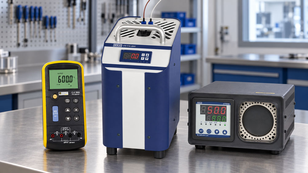
WIKA CTD9100-ZERO – defined 0 °C reference junction
The WIKA CTD9100-ZERO is a compact ice-point or 0 °C block calibrator. Its intended applications explicitly include temperature control of thermocouple reference junctions.
This makes the instrument particularly suitable for test benches and calibration laboratories where a reproducible external reference temperature is required for thermocouple measurements.
Temperature calibrators for the measuring junction
Various Temperature Calibrators are available for generating the actual test temperature. Depending on the temperature range and required measurement uncertainty, dry-block calibrators, liquid baths or calibration furnaces may be used.
For demanding comparison calibrations, a traceably calibrated external reference sensor should be positioned as close as possible to the thermocouple. This allows control deviation, loading effects and local temperature gradients within the calibration source to be detected more accurately.
C.A 1621 – thermocouple and mV calibrator
The C.A 1621 can measure and simulate thermocouple signals of types J, K, T, E, R, S, B and N as well as voltages in the mV range.
It is therefore particularly suitable for electrical testing of thermocouple measuring chains and for troubleshooting displays, controllers and transmitters. For a complete physical calibration of the thermocouple sensor itself, an additional defined temperature source is required.
Thermocouples and calibration accessories
An overview of suitable Thermocouples is also available from ICS Schneider Messtechnik.
Under ICS Components and Accessories, thermocouples, connectors, calibration blocks, miniature fixed-point cells and ice-point reference junctions are also available.
18. Conclusion
When calibrating a thermocouple with an external reference junction, two separate temperature references must be correctly controlled.
The actual calibration temperature at the measuring junction is determined, for example, using a traceably calibrated reference thermometer in a dry block, liquid bath or calibration furnace. At the same time, the thermoelectric voltage measurement requires a defined reference junction.
If this reference junction is maintained at 0 °C, the measured thermoelectric voltage directly corresponds to the 0 °C-referenced function of the respective thermocouple type. If the reference junction is at another known temperature, its thermoelectric voltage contribution must be taken into account mathematically.
The connecting cable is equally important. Thermocouple, extension and compensating cables are part of the thermoelectric circuit. Their type, polarity, tolerances and the locations of transition points can influence the calibration result.
For low measurement uncertainties, temperature stability, homogeneity, immersion depth, heat conduction, mV measurement uncertainty and, particularly with used thermocouples, possible conductor inhomogeneity must also be taken into account.
A reliable thermocouple calibration therefore involves more than simply “placing the sensor in the calibrator and reading the temperature”. The decisive factor is a complete assessment of the thermal and electrical measuring chain.
19. Frequently asked questions about thermocouple calibration with an external reference junction
What is the external reference junction of a thermocouple?
The external reference junction is the defined region in which the thermocouple conductors transition to other conductor materials – typically copper. The temperature of these transition points must be known so that the temperature of the measuring junction can be determined from the measured thermoelectric voltage.
Does a reference junction always have to be at 0 °C?
No. In principle, it can have another known temperature. However, the thermoelectric voltage that the thermocouple type used would generate between this reference temperature and 0 °C must then be taken into account in the calculation. 0 °C is particularly practical because the standardized thermocouple reference functions are based on this point.
Why is an ice point often used for precise thermocouple calibrations?
The ice point provides a highly reproducible practical temperature reference close to 0 °C. When realized correctly, it can provide a very stable external reference junction. Alternatively, specially designed 0 °C calibrators can be used.
Are ice cubes and tap water sufficient for a precise 0 °C reference?
Not automatically. For an accurate ice-point reference, the setup, ice-to-water ratio, purity, immersion depth, thermal coupling and heat input through the conductors must be taken into account. For high-quality calibrations, a defined setup or suitable reference junction source should be used.
What is the difference between the reference junction and the reference thermometer?
The reference thermometer determines the actual temperature at the measuring junction being calibrated. The reference junction, by contrast, defines the electrical reference temperature of the thermocouple circuit. A comparison calibration therefore frequently requires both.
Can the internal cold-junction compensation of a measuring instrument be used instead of an external reference junction?
Yes, depending on the required measurement uncertainty. Internal cold-junction compensation is very practical and is sufficient for many industrial tests. In demanding laboratory setups, however, an externally controlled reference junction can provide a lower and more transparent uncertainty.
Why must the connecting cable match the thermocouple type?
Because the cable is part of the thermoelectric circuit. Extension and compensating cables have defined thermoelectric properties for the respective thermocouple type. An incorrect cable can generate additional thermoelectric voltages and therefore systematic temperature errors.
Can ordinary copper cable be used after the external reference junction?
Yes, provided that the reference junction is clearly defined at the transitions from the thermocouple or compensating material to copper and both transitions have the same known temperature. From this point onward, the mV signal can be routed to the measuring instrument using suitable copper conductors.
What happens if the positive and negative conductors are reversed?
The polarity of the thermoelectric voltage is reversed. Depending on the temperature conditions, this results in strongly incorrect or opposite-direction indications and must therefore always be checked when preparing the test setup.
Can a thermocouple be calibrated using a dry-block calibrator?
Yes. Dry-block calibrators are very well suited to many industrial thermocouple calibrations. For low measurement uncertainties, however, immersion depth, block homogeneity, bore size, thermal coupling and the position of the external reference sensor must be taken into account.
Why is immersion depth important for thermocouples?
If the immersion depth is insufficient, heat can be conducted along the sensor to the surroundings. The actual measuring junction may then fail to fully reach the temperature of the calibration zone. This creates an additional deviation.
Why can a used thermocouple produce different results at different immersion depths?
Long-term temperature exposure, chemical influences or changes in the material structure can make the thermoelectric properties of the wire inhomogeneous along its length. If such a section is moved into a different temperature gradient by changing the immersion depth, the resulting thermoelectric voltage may change.
Which standard is relevant for thermocouple characteristics?
IEC 60584-1 defines the reference functions and tolerances for various standardized thermocouple types. The thermoelectric voltages specified in the standard are referenced to a reference junction at 0 °C. IEC 60584-3 is particularly relevant for extension and compensating cables.
Is the tolerance class of a thermocouple the same as its calibration uncertainty?
No. A tolerance class describes the permissible deviation of a thermocouple according to the applicable specification. A calibration, on the other hand, determines the individual deviation of a specific device under test at defined calibration points. Measurement uncertainty additionally describes the uncertainty with which this deviation was determined.
Which values should be documented during calibration?
At a minimum, the reference temperature, thermoelectric voltage, reference junction temperature or 0 °C reference used, thermocouple temperature calculated from these values, deviation and measurement uncertainty should be documented. Information on thermocouple type, connecting cable used, immersion depth, calibration equipment and measuring point setup is also useful.
What information does ICS Schneider require for selecting a suitable calibration setup?
Useful information includes the thermocouple type, sensor design and diameter, required temperature range, required measurement uncertainty, number of calibration points, desired external reference junction, existing connecting cable, number of sensors to be tested simultaneously, as well as requirements relating to documentation, DAkkS calibration and mobile or stationary use.