


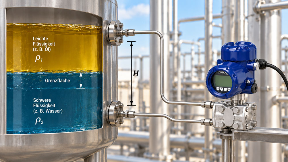
Separators, storage tanks and process vessels often contain two immiscible liquids at the same time. Typical examples include oil and water, organic and aqueous phases, or different process liquids with a sufficiently large density difference. For process control, it is then not only the overall level that is important, but above all the position of the interface between the two liquids.
A proven method for detecting this interface is differential pressure measurement. It uses the hydrostatic pressure generated by the two liquid columns between two measuring points. The method is technically relatively simple, can be used in open and closed vessels and can be implemented using industrial differential pressure transmitters and diaphragm seals.
However, this apparent simplicity has one essential prerequisite: The relationship between differential pressure and interface height depends directly on the densities of both liquids. If, for example, only the density of the upper phase changes, the measured differential pressure already shifts. If the density of the lower phase also changes at the same time, both the zero point and the measuring span of the interface measurement change.
A measuring point that has once been scaled for two nominal densities can therefore provide a plausible and stable measured value during temperature, concentration or product changes even though the actual interface is located at a different position.
The key point is: Differential pressure interface measurement does not determine the interface height directly. It initially measures the hydrostatic pressure of a column consisting of two liquids. Only if the densities are known or sufficiently constant can the position of the interface be determined unambiguously from this value.
Table of Contents
- 1. How does interface measurement using differential pressure work?
- 2. What role do the densities of both liquids play?
- 3. Why the density difference determines the measuring span
- 4. What happens if one or both densities change?
- 5. Temperature as the most common cause of density changes
- 6. Why total level and measuring points must be considered
- 7. Correctly evaluating vessel geometry
- 8. Diaphragm seals and capillaries as part of the measuring system
- 9. Correctly configuring the differential pressure transmitter
- 10. When density compensation is required
- 11. Correctly evaluating emulsion and transition layers
- 12. Systematically diagnosing typical measurement errors
- 13. Defining limits and alarms appropriately
- 14. Selection criteria for the measuring point
- 15. When another measuring principle may be more suitable
- 16. Suitable measurement technology from ICS Schneider
- 17. Conclusion
- 18. Frequently asked questions about interface measurement using differential pressure
1. How does interface measurement using differential pressure work?
Hydrostatic pressure measurement is based on a simple physical relationship. Due to its mass, a liquid column generates a pressure that increases with the height of the liquid column and its density.
For a single homogeneous liquid:
p = ρ · g · h
Here, ρ represents the density of the liquid, g the acceleration due to gravity and h the height of the liquid column.
In interface measurement, however, two liquids with different densities are located between two pressure measuring points. In a typical arrangement, the lighter liquid is on top and the heavier liquid is below. The interface is located somewhere between the lower and upper measuring points.
The differential pressure then results from the sum of the hydrostatic pressure components of both liquid columns. If the interface moves upward, more of the heavier liquid and less of the lighter liquid is present within the fixed measuring distance. The differential pressure increases. If the interface moves downward, the proportion of lighter liquid increases and the differential pressure decreases.
The interface position can be determined from this pressure change – but only unambiguously if the densities of both phases are known.
2. What role do the densities of both liquids play?
For the following analysis, let H be the fixed vertical distance between the lower and upper measuring points. The height of the heavier lower liquid within this range is designated as h.
The lower liquid has the density ρheavy, while the upper liquid has the density ρlight.
In simplified form:
Δp = g · [ρheavy · h + ρlight · (H − h)]
Rearranged:
Δp = g · [ρlight · H + (ρheavy − ρlight) · h]
This form clearly demonstrates why both densities are important. The density of the upper phase determines a significant base component of the differential pressure. The difference between the heavier and lighter liquids, on the other hand, determines how strongly the differential pressure changes when the interface moves.
If the measured differential pressure is known and the interface height h is to be calculated, the following applies:
h = [Δp / g − ρlight · H] / (ρheavy − ρlight)
This immediately shows that without knowing ρlight and ρheavy, the interface height cannot be calculated unambiguously from the differential pressure.
3. Why the density difference determines the measuring span
If the interface is exactly at the level of the lower measuring point, only the lighter liquid is present between the two measuring points. The differential pressure is then:
Δpmin = ρlight · g · H
If the interface is at the upper measuring point, the entire region between the diaphragm seals is filled with the heavier liquid:
Δpmax = ρheavy · g · H
The usable differential pressure span for interface movement is therefore:
ΔpSpan = (ρheavy − ρlight) · g · H
This formula is particularly important for sizing the measurement. It is not the absolute density of one individual liquid that determines the sensitivity of the interface measurement, but the density difference between the two phases.
The smaller this density difference is, the smaller the differential pressure between a completely light-filled and completely heavy-filled measuring section becomes. This increases the requirements placed on the transmitter, diaphragm seals, installation, temperature stability and calibration.
| Process condition | Effect on the Δp signal | Consequence for interface measurement |
|---|---|---|
| Large density difference | Large usable pressure span | Favorable measuring conditions |
| Small density difference | Small usable pressure span | Higher relative sensitivity to disturbing influences |
| Density of the upper phase increases | Lower reference point of the Δp range increases | Calculated interface may appear to shift |
| Density of the lower phase decreases | Upper reference point decreases | Measuring span becomes smaller |
| Both densities change | Zero point and measuring span can shift simultaneously | Fixed scaling may no longer be correct |
4. What happens if one or both densities change?
A conventional differential pressure interface measurement is generally designed for two specified densities. These values determine the differential pressures for the lower and upper limits of the measuring range.
If the actual densities change during operation, the measured differential pressure also changes even if the actual interface does not move at all.
This is an important distinction from a conventional sensor error. The transmitter may measure the actual differential pressure perfectly correctly. The error only arises when this pressure is interpreted as interface height because the calculation still uses the originally configured densities.
The situation becomes particularly challenging if both liquids undergo density changes at the same time. In this case, both the base pressure contribution of the lighter phase and the density difference between the two phases can change.
A single differential pressure value then does not contain enough information to simultaneously determine an unknown interface height and two unknown liquid densities.
The problem is mathematically ambiguous unless additional information about the current densities is available.
Example: Density change without actual interface movement
Assume that the interface remains completely stationary in the vessel. Due to an increase in temperature, however, the density of the lower liquid decreases. Its hydrostatic pressure contribution therefore becomes smaller and the differential pressure decreases.
A control system that continues to calculate using the original density interprets this pressure reduction as a downward movement of the interface – even though the interface has not moved at all.
The same principle applies to a density change in the upper liquid. For this reason, considering only the density of the heavier phase is not sufficient in two-phase systems.
5. Temperature as the most common cause of density changes
The density of many liquids depends significantly on temperature. When a liquid is heated, its density generally decreases. However, the magnitude of this effect depends strongly on the medium.
In a two-phase measurement, both phases may heat up by different amounts or have different temperature coefficients. As a result, not only the absolute density but also the density difference between the two liquids may change.
Simple temperature compensation therefore only works reliably if dependable relationships between temperature and density are available for both media.
It is also important to determine which temperature is actually used for the calculation. Temperature gradients can occur in large vessels. The temperature at the top of the vessel may therefore not correspond to the temperature in the lower liquid section.
For processes with large temperature variations, it should therefore already be clarified during the planning stage whether the densities remain practically constant, whether temperature-dependent density curves are available or whether additional process information is required.
6. Why total level and measuring points must be considered
For conventional differential pressure interface measurement between two side-mounted measuring points, the interface must remain within the range defined by these measuring points.
The upper measuring point must also remain covered by liquid. If the total level falls below this point, the hydraulic conditions change fundamentally. The previously used relationship for determining the interface is then no longer valid.
This aspect is sometimes overlooked in practice when the total level in a separator varies considerably.
If, on the other hand, the total level remains permanently above the upper measuring point and both measuring points are hydraulically connected to the process, the pressure contribution above the upper measuring point acts on both sides according to the selected arrangement and does not influence the hydrostatic difference between the two measuring points in the same way as a conventional bottom-to-vapor-space differential pressure level measurement.
The actual diaphragm seal and connection arrangement must therefore always be included in the calculation. An interface measurement using two side-mounted, permanently flooded diaphragm seals must not automatically be treated in the same way as conventional differential pressure level measurement between the bottom of the vessel and the vapor space.
7. Correctly evaluating vessel geometry
Differential pressure initially depends on the vertical height of the liquid columns and not directly on the vessel volume. The geometric shape of the vessel therefore does not change the fundamental hydrostatic relationship between the measuring points and the interface height.
However, vessel geometry can still be very important for process control.
In a vertical cylindrical vessel with a constant cross-section, a certain change in interface height corresponds to a proportional change in the volume of the lower phase. In a horizontal cylindrical tank, a vessel with dished ends or a conical separator, this relationship is not linear.
If not only the interface height but also the volume of one phase is to be calculated, vessel linearization or a geometric characteristic curve is therefore required.
Internals, calming plates and separator chambers must also be taken into account. The interface at the measuring location must be representative of the interface that is actually relevant to the process.
8. Diaphragm seals and capillaries as part of the measuring system
In many interface applications, the two process pressures are transferred to the differential pressure transmitter via diaphragm seals and capillary lines. This provides a closed measuring arrangement and can offer advantages with aggressive, contaminated, viscous or hygienically demanding media.
However, diaphragm seals and capillaries are not metrologically neutral connecting elements. Their fill fluid also has a temperature-dependent density and temperature-dependent volume.
Different capillary lengths, different elevation levels or different ambient temperatures can therefore generate additional zero-point shifts.
In an interface measurement with a comparatively small usable Δp span, such effects can account for a significant proportion of the overall error budget.
For this reason, both capillaries should be designed as symmetrically as possible and exposed to comparable temperature conditions. The installation position of the differential pressure transmitter and the elevation differences between diaphragm seals and measuring cell must also be considered during sizing.
9. Correctly configuring the differential pressure transmitter
During commissioning, the lower and upper differential pressure values for the intended interface range are defined.
For the simplified case of two measuring points with the vertical distance H:
Lower interface at the lower measuring point:
Δpmin = ρlight · g · H
Interface at the upper measuring point:
Δpmax = ρheavy · g · H
These two values can then, for example, be assigned to the 4 mA and 20 mA output points.
Additional hydrostatic contributions from diaphragm seals, capillaries and the actual installation height must also be taken into account. Such scaling should therefore not be based solely on a simplified formula if the real installation differs from the simplified arrangement.
Correct selection of the differential pressure measuring range is particularly important. With small density differences, the actual interface span may be only a few millibars even though a high static process pressure is present on both sides at the same time.
The transmitter must therefore be capable of reliably measuring a sufficiently small differential pressure span while also being suitable for the maximum static pressure that can occur.
10. When density compensation is required
Density compensation becomes relevant when density fluctuations during normal operation become large enough to cause an unacceptable deviation in the calculated interface height.
There are several possible approaches.
If both liquids are clearly known and their densities primarily change with temperature, stored density-temperature characteristic curves can be used. This requires that the current temperature of each phase is measured sufficiently representatively and that the composition of the liquids otherwise remains constant.
If concentration or composition also changes, temperature compensation alone may not be sufficient. In this case, the current densities must be determined by other means or calculated from additional process variables.
The corrected interface height can then be calculated in a PLC, process control system or suitable evaluation unit.
It is important to understand that the differential pressure transmitter continues to provide only the measured differential pressure. Dynamic correction of the interface position is performed using additional information about the process densities.
| Process condition | Suitable approach | Limitation of the method |
|---|---|---|
| Both densities practically constant | Fixed DP scaling | Changes outside the design values cause measurement errors |
| Densities change reproducibly with temperature | Temperature-dependent density compensation | Density-temperature characteristic curves must be known |
| Composition of one phase changes | Additionally determine or calculate current density | Temperature alone may not be sufficient |
| Both densities unknown and variable | Consider additional measured variables or another measuring principle | A single Δp measurement is mathematically ambiguous |
| Density difference becomes very small | Reassess the measuring principle fundamentally | Usable Δp span may become too small |
11. Correctly evaluating emulsion and transition layers
The analysis above assumes two clearly separated liquids with a clearly defined interface. In real separators, however, this is not always the case.
Between oil and water, for example, a more or less broad emulsion layer can form. Within this zone, the composition and therefore the density change continuously.
In this case, differential pressure measurement detects the integrated hydrostatic effect of the entire liquid column. It does not automatically determine where a particular concentration boundary lies within a transition zone that may be several centimeters or decimeters wide.
The “interface value” shown in the control system is then a quantity derived from the overall hydrostatic condition and does not necessarily represent a geometrically sharp boundary between two homogeneous liquids.
For applications with pronounced emulsion layers, it should therefore be determined which physical boundary is actually required for the process and whether the differential pressure method can represent it sufficiently unambiguously.
12. Systematically diagnosing typical measurement errors
An incorrect interface indication does not automatically mean that the differential pressure transmitter is defective. In this type of measurement, many deviations originate outside the actual measuring cell.
| Observation | Possible cause | Recommended check |
|---|---|---|
| Interface appears to shift with process temperature | Density change in one or both phases | Compare temperatures and current liquid densities |
| Deviation after product change | New liquid densities no longer match the parametrization | Check media and density data and recalculate scaling |
| Signal range becomes smaller | Density difference between the two liquids has decreased | Determine ρheavy − ρlight under operating conditions |
| Measured value changes with ambient temperature | Temperature influence on capillaries or fill fluid | Check temperature conditions of both diaphragm seal systems |
| Indication no longer matches after maintenance | Installation height, capillary routing or parametrization changed | Check mechanical arrangement and zero point |
| Signal responds only weakly to actual interface movement | Very small density difference or measuring span too large | Calculate the expected theoretical Δp span |
| Unstable or delayed indication | Emulsion zone, blocked connection or sluggish diaphragm seal system | Investigate process conditions and hydraulic measuring connection |
| Indication becomes implausible at low total level | Upper measuring point no longer fully covered | Check total level separately |
Also consider the raw measured differential pressure
For troubleshooting, it is very helpful not to look exclusively at the interface indication that has already been converted into percent or millimeters.
The actual differential pressure in mbar or Pa shows what the transmitter is physically measuring. It can then be checked whether this pressure is consistent with the current liquid densities and the actual interface position.
This makes it easier to distinguish between a sensor problem, incorrect scaling or an actual change in process densities.
13. Defining limits and alarms appropriately
In separators, interface measurement is often used not only for indication. It may, for example, control a drain function or trigger an upper or lower limit alarm.
If the interface height calculated from differential pressure has a relevant uncertainty caused by density fluctuations, this uncertainty also directly affects the switching points.
An alarm at, for example, 70% interface height is only reliable if the conversion from differential pressure to percentage remains sufficiently accurate under the actual process conditions.
For operationally or safety-critical functions, it should therefore be evaluated whether additional independent limit detection is required. Continuous differential pressure measurement does not automatically replace an independently designed protective function.
14. Selection criteria for the measuring point
When selecting a differential pressure transmitter, it is not sufficient to specify only the desired interface range. The expected differential pressure must first be calculated from the actual process data.
The minimum and maximum densities of both liquids are particularly important. The relevant values are not only those at room temperature, but the densities under actual operating conditions.
In addition, the maximum static vessel pressure, minimum and maximum process temperature, vertical distance between the measuring points, diaphragm seal design, capillary lengths, material requirements and any Ex requirements must be known.
The question of whether the interface always remains within the intended measuring range and whether the upper measuring point remains permanently covered is also part of the fundamental design data.
The smaller the density difference between the two phases, the more carefully the differential pressure measuring range must be selected. An unnecessarily large measuring range reduces the usable resolution of the actual interface information.
15. When another measuring principle may be more suitable
Differential pressure measurement is particularly attractive when two well-known liquids with sufficiently stable and clearly different densities are present.
If the densities become highly variable or approach each other, another measuring principle may offer advantages.
Guided wave radar or TDR can, depending on the dielectric constants of the two liquids, directly detect an interface. Capacitive, magnetostrictive or float-based methods can also be considered depending on the medium, pressure, temperature and process configuration.
However, these methods are not automatically suitable either. A float, for example, requires a defined density, while TDR requires sufficient differences in the electrical properties of the media. Emulsions, foam, deposits or very small differences in physical properties can also impair alternative methods.
Selection should therefore not be based on the supposedly “most modern” measuring principle, but on the actual process conditions.
16. Suitable measurement technology from ICS Schneider
ICS Schneider Messtechnik offers various solutions for hydrostatic level, differential pressure and interface applications. An overview can be found in the Level Measurement Technology category.
For differential pressure applications, various Differential Pressure Sensors and Differential Pressure Transmitters are also available.
WIKA DPT-20
The WIKA DPT-20 Differential Pressure Transmitter is designed for industrial differential pressure and level measurement applications. The manufacturer’s documentation explicitly describes interface measurement using two diaphragm seals.
For this application, the distance between the measuring points and the densities of both liquids are used to determine the lower and upper differential pressure values. Diaphragm seals also allow adaptation to difficult process media and process connections.
Siemens SITRANS P320
The Siemens SITRANS P320 is available in versions for differential pressure and level measurement and offers, among other features, HART communication and extensive diagnostic functions.
For an interface application, measuring range, process connections or diaphragm seals, static pressure and the required signal evaluation must be matched to the specific measuring point.
Further information on the influence of density, temperature and medium on hydrostatic level measurement can be found in the technical article “Level Measurement with Difficult Media: Consider Density, Viscosity and Temperature”.
For closed and pressurized vessels, the technical article “Measuring Level in a Pressurized Tank: Correctly Compensating Vapor-Space Pressure” is also relevant.
17. Conclusion
Interface measurement using differential pressure is a proven method for vessels containing two immiscible liquids of different densities. Its physical principle is simple, but correct application requires careful consideration of the entire process.
The transmitter does not directly measure the position of the interface. It measures the hydrostatic differential pressure between two process points. This differential pressure consists of the pressure contributions from the heavier and lighter liquids.
The calculated interface height therefore necessarily depends on the densities of both media. The density of the upper phase influences the starting point of the characteristic curve, while the difference between the two densities determines the usable measuring span in particular.
With constant densities, the interface position can be determined very effectively using fixed differential pressure scaling. If, however, the density of one or both liquids changes, the measuring signal can shift even though the actual interface remains unchanged.
If the current densities are known from temperature measurement, fluid property data or additional process measurements, suitable compensation can be applied. If, on the other hand, the interface height and both densities are unknown at the same time, a single differential pressure value is no longer sufficient for an unambiguous determination.
In addition, the distance between measuring points, total level, diaphragm seals, capillaries, ambient temperature, static pressure and possible emulsion layers must also be taken into account.
A reliable interface measurement therefore does not begin with selecting the differential pressure transmitter, but with a complete description of the media, densities and their fluctuations, temperature, vessel geometry and operating conditions.
18. Frequently asked questions about interface measurement using differential pressure
Can a differential pressure transmitter measure the interface between two liquids?
Yes. The prerequisite is that the two liquids have different densities and that the measuring arrangement is designed accordingly. The interface must remain within the intended range between the two measuring points.
Why must the densities of both liquids be known?
The differential pressure consists of the hydrostatic contributions of both liquid columns. The interface height can therefore only be calculated if both the density of the upper and the density of the lower liquid are known.
What happens if only the density of the upper liquid changes?
The measured differential pressure changes even if the interface position remains unchanged. At the same time, the density difference between the two liquids and therefore potentially the measuring span also changes.
What happens if both densities change?
Both the starting point and the slope of the relationship between differential pressure and interface height can change. A fixed 4…20 mA scaling based on the original densities can therefore produce incorrect interface values.
Can the differential pressure transmitter automatically detect these density changes?
A conventional differential pressure transmitter initially measures only the differential pressure. Without additional information, it cannot distinguish whether a pressure change was caused by interface movement, a density change or a combination of both.
Can density be compensated using temperature?
Yes, provided that reliable density-temperature relationships are known for both liquids and their compositions otherwise remain sufficiently constant. If concentration or product composition also changes, temperature compensation alone may be insufficient.
Why is the density difference so important?
The usable differential pressure span of the interface measurement is proportional to the difference between the density of the lower and the upper liquid. The smaller this difference becomes, the smaller the signal generated by the same interface movement.
Can an interface be measured if both liquids have nearly the same density?
In principle, the differential pressure signal then becomes very small. At a certain point, measurement uncertainty, temperature effects and other disturbing influences may become too large relative to the actual interface information. Another measuring principle should then be considered.
Does the total level have to remain constant?
With an arrangement using two permanently flooded measuring points, the total level above the upper measuring point may vary. However, it is important that the upper measuring point remains covered and that the interface stays between the two measuring points. Other arrangements, for example between the bottom of the vessel and the vapor space, must be considered separately.
Can this measurement be used in a closed pressurized vessel?
Yes. Differential pressure measurements can also be used in closed vessels. The specific arrangement must ensure that the static vessel pressure or common pressure components are correctly taken into account.
Why are diaphragm seals often used?
Diaphragm seals isolate the measuring cell from direct contact with the process medium and can be useful, among other applications, with aggressive, viscous, contaminated or hot media. They also provide suitable process connections. However, the diaphragm seal and capillary systems themselves must be considered with regard to temperature and elevation effects.
Why should both capillaries be exposed to similar temperatures wherever possible?
Temperature changes influence the fill fluid in the capillaries. Different thermal conditions on the two sides can therefore generate an additional differential pressure or zero-point shift.
Can a broad emulsion layer be reliably measured as an interface?
Differential pressure measurement detects the overall hydrostatic effect of the liquid column. With a broad emulsion zone, there may be no sharp geometric interface. The calculated interface value must therefore be interpreted according to the process definition.
How is the measuring range of a differential pressure transmitter determined for interface measurement?
It is calculated from the distance between the measuring points and the densities of the two liquids. If applicable, hydrostatic influences from diaphragm seals, capillaries and installation elevations must also be taken into account.
Which transmitter is suitable for this type of measurement?
A suitable differential pressure transmitter must be able to measure the expected small differential pressure span with sufficient accuracy while also being suitable for the maximum static process pressure, process media, temperature and required approvals. According to the manufacturer’s documentation, the WIKA DPT-20 explicitly supports interface measurement.
What information does ICS Schneider require for sizing the measurement?
In particular, the two liquids, minimum and maximum densities under operating conditions, temperature range, vessel pressure, required interface range, distance and position of the measuring points, vessel geometry, process connections, material requirements as well as information on hazardous-area requirements, output signal and required measurement accuracy are needed. For variable densities, it should also be described why and within which range these densities change.