


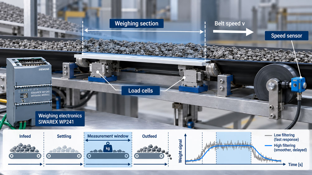
In dynamic weighing on a conveyor belt, the measured value is generated while the material is moving. This is the fundamental difference from a static scale. The load cell or weighbridge is not subjected to a stationary load, but to a force that builds up, changes and then disappears again during transport.
At the same time, mechanical vibrations, roller movements, changes in belt tension, impact forces during material transfer and electrical interference affect the weighing signal. The weighing electronics must generate a measured value from this time-dependent signal that is sufficiently stable and at the same time available quickly enough.
A common response to an unstable weighing signal is to increase the amount of filtering. This does indeed make the displayed weight value steadier. In a dynamic application, however, precisely this measure can create a new problem: The filtered measured value may not reach a usable state until the conveyed material has already left the actual weighing section or the belt loading has already changed.
The decisive question is therefore not: “How much filtering do I need to make the weight reading look stable?”
Instead, the key question is: How much time is actually available for the measurement, and how quickly must the complete measuring chain deliver a reliable value within this time?
The key point is: In dynamic weighing, the mechanical design, weighing section, belt speed, load cell dynamics, filter settings and evaluation time must be considered together. A stable measured value is only useful if it is available within the available process time window.
Table of Contents
- 1. What does dynamic weighing on a conveyor belt mean?
- 2. Distinguishing individual product weighing from continuous belt weighing
- 3. How is the available measurement window created?
- 4. Why belt speed directly affects measurement time
- 5. Consider mechanical settling before signal filtering
- 6. Why a filter stabilizes the signal while also delaying it
- 7. Correctly coordinating filter time and cutoff frequency
- 8. Distinguishing low-pass filtering from averaging
- 9. The speed signal also has dynamic behavior
- 10. Weighing section and residence time as design parameters
- 11. Do not confuse sampling rate with filter bandwidth
- 12. Diagnosing typical dynamic measurement errors
- 13. Systematically optimizing the measuring system
- 14. Correctly calibrating and verifying dynamic measurement
- 15. Selection criteria for load cells and weighing electronics
- 16. Suitable weighing technology from ICS Schneider
- 17. Conclusion
- 18. Frequently asked questions about dynamic weighing on conveyor belts
1. What does dynamic weighing on a conveyor belt mean?
With a static scale, a load is applied and then sufficient time is allowed for the mechanics and measuring signal to stabilize. The time until the measured value is accepted can often be selected comparatively generously.
In a conveyor belt application, however, the material continues moving. The available time is determined by the mechanics and the process speed.
The weighing signal therefore develops over time. As the conveyed material enters the weighing section, the load increases. Mechanical structures deflect, rollers and belt respond to the load, and the load cell generates a corresponding electrical signal.
After this transition, a region may develop in which the signal is sufficiently representative of the actual load. The conveyed material then leaves the weighing section or the distribution of material changes again.
The weighing electronics must identify the usable part of this signal profile and process it so that a sufficiently accurate value is obtained.
This makes one point clear: The dynamic behavior of a belt scale is not determined solely by the load cell. The entire system is part of the measuring system.
2. Distinguishing individual product weighing from continuous belt weighing
The term “dynamic weighing on conveyor belts” is used for different measurement tasks. This distinction is important when evaluating filter time and the measurement window.
Dynamic individual product weighing
In dynamic individual product weighing or checkweighing, individual products are weighed during transport. A carton, container or workpiece moves onto a defined weighing platform or weighing belt, is measured while in motion and subsequently leaves the weighing station again.
In this case, there is in fact a clearly limited measurement window. The product is fully or sufficiently defined on the weighing device only for a certain period of time.
Continuous conveyor belt scale
With a conventional belt scale for bulk solids, on the other hand, there is a continuous material flow. The weighbridge determines the belt loading while a speed sensor measures the current belt speed.
The instantaneous mass flow rate can be simplified as:
Mass flow rate = belt loading × belt speed
Here, there is no equivalent individual measurement window for each product. Instead, the length of the weighing section, the residence time of the material on this section, the determination or evaluation time and the filtering of the continuous signals are decisive.
| Application | Time-related consideration | Particularly important |
|---|---|---|
| Individual product weighing | Limited measurement window per product | Product length, weighing belt length, belt speed, trigger timing |
| Continuous belt scale | Continuous measurement | Weighing section, belt loading, speed, filtering and integration |
| Weigh feeder | Continuous measurement with control | Additionally, control behavior and response time of the feeding process |
The fundamental physical issue is similar in all three cases: The faster the process runs, the less time remains for mechanical settling and signal processing.
3. How is the available measurement window created?
With dynamic individual product weighing, the available time window can be derived very clearly from the geometry and belt speed.
If the effective weighing belt has the length LW and the product has the length LP in the conveying direction, the product is fully supported on the weighing platform only if:
LW > LP
For an idealized calculation, the time during which the product is fully on the weighing section is approximately:
tfull = (LW − LP) / v
where v is the belt speed.
An example illustrates the relationship:
If the weighing belt is 800 mm long, the product is 400 mm long and the belt speed is 1 m/s, the theoretical time available is:
t = (0.8 m − 0.4 m) / 1 m/s = 0.4 s
for the fully supported condition.
However, these 400 ms are not fully available for ideal measured-value generation. Part of the time is required for mechanical settling, signal processing and, where applicable, safety margins at the infeed and outfeed.
If the belt speed is increased to 2 m/s, the geometrically available time window is already reduced by half to 200 ms.
This is precisely why a system may weigh perfectly at a low speed but suddenly show significantly greater variation after a productivity increase, even though the load cell, calibration and mechanics have not been changed.
4. Why belt speed directly affects measurement time
A higher belt speed increases throughput. From a metrological perspective, however, it initially means less time per distance travelled.
For a conveyor section of length L, the following basic relationship applies:
t = L / v
If the speed doubles while the weighing section remains unchanged, the residence time is halved.
This does not affect only individual products. With a continuous belt scale, speed also changes how long a particular section of material acts on the weighbridge.
When belt loading changes rapidly, the weighing system must therefore be able to respond faster if the same local material structure is still to be captured with sufficient time resolution.
A subsequent increase in conveying speed should therefore never be regarded purely as a mechanical change. It simultaneously changes the requirements placed on:
- the weighbridge,
- the load cell,
- speed measurement,
- filtering,
- evaluation and
- control-system response.
5. Consider mechanical settling before signal filtering
An unstable signal is often initially attributed to the electronics. In many cases, however, a significant proportion of the fluctuation already originates mechanically.
When material enters a weighing section, it does not apply only a static gravitational force. Additional vertical and horizontal force components may also occur.
Typical causes include transitions between conveyors, different belt heights, impact loads, uneven product support, roller runout, changing belt tension or vibration of the machine frame.
The natural frequency of the weighing mechanism also plays a role. A lightweight weighing platform can respond quickly, while a heavy and elastically mounted structure may take longer to settle after a load change.
Very strong digital filtering can visually conceal such mechanical problems. However, it does not eliminate their cause.
Before selecting more aggressive filtering, it should therefore be checked whether the force introduction itself can be improved.
Avoid force shunts
Forces that bypass the load cell are particularly critical. Rigid cables, piping, protective covers, guides or mechanical stops can transfer part of the weight force directly into the machine frame.
In a dynamic system, such parasitic forces can change with movement. This can create a measurement deviation that may hardly be visible during a static test.
The mechanical structure and load cell must therefore be considered as one system.
6. Why a filter stabilizes the signal while also delaying it
The raw signal from a load cell can contain oscillation components that are irrelevant to the actual weight value. Digital filters reduce such signal components.
The basic behavior of a low-pass filter is easy to understand: Slow changes are largely transmitted, while fast changes are attenuated depending on their frequency and the filter setting.
For a scale, this is initially desirable. Mechanical vibration and short-term disturbances produce less pronounced fluctuations in the displayed weight.
However, every filter also has a time-related effect. The more strongly the signal is stabilized, the more slowly the filtered value responds to a real change in weight.
This trade-off is central to dynamic weighing:
| Filter setting | Advantage | Disadvantage |
|---|---|---|
| Low filtering | Fast response | Interference and vibration remain more visible |
| Medium filtering | Compromise between stability and dynamics | Must be adapted to the specific machine |
| Strong filtering | Very stable measured value | Greater delay and possible smearing of rapid changes |
The “best” filter setting is therefore not the one that produces the steadiest display. The correct setting is the one that provides sufficiently stable and sufficiently fast weight information within the available measurement window.
7. Correctly coordinating filter time and cutoff frequency
Depending on the weighing electronics, dynamic behavior is not necessarily set directly as a “filter time”, but may instead be configured, for example, as the cutoff frequency of a low-pass filter.
A low cutoff frequency means stronger suppression of fast signal components and therefore slower response. A higher cutoff frequency allows dynamic changes to pass more quickly but suppresses correspondingly less interference.
With the SIWAREX WP241, for example, the cutoff frequency of the low-pass filter can be configured separately for belt loading and speed.
The parameters should not be selected by feel. It is more useful to examine the actual signal behavior.
When a defined weight or defined material change is applied, at least the following properties should be investigated:
- rise time of the raw signal,
- existing vibration frequencies,
- time until a sufficiently stable region is reached,
- delay of the filtered signal and
- available process time before the measured value must be accepted.
A filter setting in which the measured value only becomes reliable after 500 ms may work very well in a 2-second process. With a measurement window of only 200 ms, however, the same configuration is fundamentally unsuitable.
8. Distinguishing low-pass filtering from averaging
In addition to conventional low-pass filters, moving averages are frequently used in weighing electronics.
With an averaging filter, the output value is calculated from several consecutive individual measured values.
In simplified form:
x̄ = (x1 + x2 + … + xn) / n
The more values that are included, the more strongly random fluctuations are smoothed.
At the same time, however, the information extends over a longer period. A real rapid change is therefore spread over time.
In dynamic conveyor processes, it is therefore not only important how many values are averaged, but also at what time interval these values are generated.
An average over 20 measured values at intervals of 10 ms has a different dynamic behavior from the same number of values at intervals of 1 ms.
Low-pass filters and averaging filters should therefore not simply be regarded as two different ways of making a display “steadier”. Both modify the time-related information of the weighing signal and must match the process.
9. The speed signal also has dynamic behavior
With a continuous belt scale, it is not only the belt loading that is measured. The actual belt speed is also part of the mass-flow calculation.
An incorrect or poorly time-aligned speed measurement can therefore directly result in an incorrect throughput value.
Time alignment is particularly important.
Belt loading and belt speed should represent the same actual conveying condition. If the speed signal is heavily filtered while the belt loading is almost unfiltered – or vice versa – time differences can occur between the two variables during acceleration and deceleration.
With belts running at constant speed, this effect is considerably less critical. With variable speed or controlled weigh feeders, however, it must be taken into account.
A suitable speed sensor should also measure the actual belt movement as representatively as possible.
The SITRANS WS300, for example, is coupled directly to the shaft of a bend pulley or return-belt roller and provides the weighing electronics with a pulse signal proportional to the rotational speed.
10. Weighing section and residence time as design parameters
If the available measuring time is too short, an attempt is often first made to solve the problem using faster electronics alone.
However, the mechanics also offer a highly effective parameter: the length of the weighing section.
A longer weighbridge means that a specific section of material acts on the instrumented rollers or weighing platform for a longer period.
With an individual product scale, a larger weighing platform – with unchanged product length and speed – increases the fully usable measurement window.
With continuous belt scales, a longer weighing section can help spatially average local dynamic effects or short-term load changes more strongly.
The Milltronics WD600, for example, explicitly uses a longer weighing section or slider-bed arrangement to increase the residence time of the material load on the weighing device.
This illustrates an important design principle: Dynamic measurement quality does not begin in the software. It starts with the mechanical design of the weighing station.
11. Do not confuse sampling rate with filter bandwidth
Fast weighing electronics require a sufficiently high measuring rate to capture dynamic signal profiles at all.
However, a high sampling rate alone does not guarantee a quickly available usable weight value.
The complete measuring chain can be simplified as:
mechanical load → load cell → amplifier → A/D conversion → filter → evaluation algorithm → communication → PLC or machine control system
Each of these stages can introduce a delay.
If measurements are taken at 100 Hz, for example, a new measured value is generated every 10 ms. If numerous values are subsequently averaged or strongly low-pass filtered, the effective response time can nevertheless be significantly longer.
Conversely, an extremely high sampling rate provides little benefit if the weighing mechanism itself continues oscillating for several hundred milliseconds.
For dynamic applications, a distinction must therefore be made between three parameters:
- measurement or sampling rate,
- bandwidth or filter setting and
- total time required until a usable result is available.
12. Diagnosing typical dynamic measurement errors
With a dynamic scale, the load cell should not be replaced too quickly as the first troubleshooting measure. Many errors arise from the interaction between mechanics, belt speed and signal processing.
| Observation | Possible cause | Recommended check |
|---|---|---|
| Measured value is correct at low speed but too low at higher speed | The measured value does not reach a representative region within the available time window | Reduce belt speed and compare the signal profile |
| Display is very stable but responds with a noticeable delay | Filtering too strong | Gradually increase cutoff frequency or reduce filter depth |
| Measured value varies for identical products | Mechanical vibration or inconsistent force introduction | Observe raw signal and product transfer |
| Weight depends on product position on the belt | Mechanical load distribution or lateral forces | Check weighing mechanics and guides |
| Throughput jumps during belt acceleration | Weight and speed signals not filtered with suitable time alignment | Compare both raw signals and filter settings |
| Periodic weight fluctuation | Roller runout, motor, gearbox or belt frequency | Compare frequency with belt circulation and rotational speeds |
| Measured value only becomes stable shortly before leaving the weighing section | Measurement window too short | Check belt speed, weighing section and filter time together |
| Static test is correct but dynamic measurement is not | Dynamic force components or unsuitable signal processing | Investigate static and dynamic signal profiles separately |
Examine the raw signal before changing parameters
One of the most useful diagnostic measures is to record the load-cell signal or raw weight value with as little filtering as possible.
This makes it possible to determine whether an error is already present mechanically or only arises during signal processing.
A strongly oscillating raw signal followed by a very stable display, for example, indicates successful but potentially excessive filtering.
A value that is already reproducibly shifted in the raw signal, on the other hand, points more strongly toward mechanics, force introduction or sensor technology.
13. Systematically optimizing the measuring system
A dynamic scale should not be optimized by randomly changing filter parameters until the display “looks good”.
A better approach starts with the mechanics.
First, it is checked whether the load enters the weighing section reproducibly. Transfers should generate as little vertical impact as possible. Belt tension, roller movement and machine frame must be sufficiently stable. Cables and attached components must not create uncontrolled force shunts.
The raw signal is then recorded under typical process conditions.
The signal profile can be used to estimate how long the mechanical settling process lasts and which periodic disturbances are present.
Only then should filtering be adjusted so that disturbing signal components are sufficiently reduced without delaying the desired useful signal more than necessary.
Finally, the complete measurement is checked at minimum, typical and maximum belt speed.
This shows whether the parametrization is actually robust under the different process conditions.
14. Correctly calibrating and verifying dynamic measurement
A static calibration of the load cell or weighbridge remains important even in a dynamic system. However, it does not automatically confirm that the scale operates correctly during the moving process.
With a conveyor belt scale, the zero point, mechanical weighbridge, speed measurement and evaluation electronics must therefore be considered together.
For a continuous belt scale, for example, a zero test can be carried out with the belt running empty. A suitable test load or calibration procedure can then be used to verify whether the relationship between load-cell signal and belt loading is correct.
A material test under actual conveying conditions is particularly informative. A known quantity of material is conveyed over the scale and compared with an independent reference value.
Such a test captures influences that may not be fully visible during purely static calibration.
Further details on zero point, belt speed and test load are covered in our technical article “Calibrating a Conveyor Belt Scale: Correctly Determining Zero Point, Belt Speed and Test Load”.
15. Selection criteria for load cells and weighing electronics
For dynamic applications, a load cell should not be selected solely on the basis of rated load and static accuracy.
The mechanical stiffness of the system, natural frequencies, permissible overload, lateral forces and type of force introduction also influence dynamic behavior.
The weighing electronics are equally important. They must acquire the sensor signals at a speed suitable for the application and provide suitable filtering.
For a belt scale, the speed sensor and throughput calculation are also part of the measuring chain.
For system design, at least the following data should therefore be available:
- type of conveyed material,
- minimum and maximum throughput or product weight,
- belt speed and its range of variation,
- length of the available weighing section,
- product or material geometry,
- required measurement accuracy,
- permissible measurement time or cycle time,
- mechanical installation conditions,
- existing vibrations and disturbances,
- required interfaces to the PLC or process control system.
16. Suitable weighing technology from ICS Schneider
ICS Schneider Messtechnik offers various solutions for industrial weighing and force measurement applications. An overview can be found under Force, Weighing and Displacement Measurement Technology.
Various Conveyor Belt Scales are available for continuous material flow measurement.
SIWAREX WP241 – weighing electronics for belt scales
The SIWAREX WP241 is specifically designed for belt-scale applications and can be integrated into a SIMATIC S7-1200 or used as standalone weighing electronics.
It acquires belt loading and belt speed, calculates material throughput from these values and provides various diagnostic and trace functions.
Of particular relevance to the subject covered here are the separately configurable filters for weight or belt loading and speed. This allows the signal dynamics to be specifically adapted to the respective conveying system.
Milltronics MLC
The Milltronics MLC is a compact belt scale for low flow rates and low belt loading.
Its load-cell design is intended to respond quickly to vertical forces. It is therefore particularly suitable for applications in which smaller material loads are to be measured continuously on existing flat-belt conveyors.
Milltronics WD600
The Milltronics WD600 uses a longer weighing section and is intended for low to medium loads.
The increased residence time on the weighing device clearly demonstrates that not only the electronics but also the mechanical length of the weighing section plays an important role in dynamic measurement.
SITRANS WS300 speed sensor
The SITRANS WS300 measures the belt speed and provides a corresponding pulse signal to the weighing electronics.
In continuous belt scales, this speed signal is just as important as the actual weight signal because both variables are used together to calculate the instantaneous material throughput.
17. Conclusion
Dynamic weighing on conveyor belts is not simply static weight measurement performed on a moving conveyor. It is a time-dependent measurement task in which mechanical and electronic dynamics interact directly.
Belt speed determines how long the material or an individual product acts on the weighing section. At the same time, the mechanics require a certain period to settle, and signal processing requires time for filtering and evaluation.
Stronger filtering can significantly stabilize an unstable weight value. At the same time, however, it can cause the usable value to become available too late.
The appropriate filter setting therefore cannot be selected independently of the belt speed.
Likewise, the belt speed cannot simply be increased without checking how the residence time or measurement window changes as a result.
With dynamic individual product scales, the available measurement window is directly limited by the weighing belt length, product length and speed. With continuous belt scales, the focus is instead on the weighing section, continuous belt loading, speed and filter or determination times.
For reliable measurement, the entire chain must therefore be considered:
conveyed material → conveyor belt → weighbridge → load cell → weighing electronics → filter → speed measurement → evaluation → control system.
Optimum dynamic weighing is not achieved through maximum filtering or maximum measuring rate, but through the correct coordination of mechanics, measurement dynamics and available process time.
18. Frequently asked questions about dynamic weighing on conveyor belts
What is the measurement window in dynamic weighing?
With individual product weighing, the measurement window is the period during which the test object is positioned sufficiently well-defined on the weighing section for a usable weight value to be determined. With continuous belt scales, the term is less clearly defined; weighing section, residence time, filtering and continuous determination or integration time are more relevant.
How does belt speed influence the measurement window?
The higher the belt speed, the shorter the time a product or section of material spends on a defined weighing section. With unchanged geometry, doubling the speed generally halves the residence time.
Why might the scale indicate a different weight at high speed?
One possible cause is that the mechanics and filtered signal have not yet reached a sufficiently representative condition within the shorter available time. Stronger impact and vibration effects may also occur.
Is the strongest possible filtering always better?
No. Strong filtering does produce a stable measured value, but it also increases the time delay. In a fast application, the value may therefore only become available after the usable measurement window has already ended.
What does a low low-pass cutoff frequency mean?
A low cutoff frequency suppresses fast signal changes more strongly. This makes the weight value steadier, but it also responds more slowly to real load changes.
What is the difference between a low-pass filter and an averaging filter?
A low-pass filter suppresses signal components depending on their frequency. An averaging filter, on the other hand, calculates a value from several consecutive measured values. Both can stabilize the signal while also influencing the time response.
Can a higher sampling rate solve the problem of excessive filtering?
No. A higher sampling rate does provide more individual measured values per unit of time, but it does not automatically eliminate the delay introduced by a downstream filter. Likewise, it cannot compensate for slow mechanical settling.
How can the available measurement time of an individual product scale be estimated?
If the product must be completely supported on the weighing section, the idealized full residence time can be approximated from the difference between weighing belt length and product length divided by the belt speed.
Why is a longer weighing section advantageous?
At the same belt speed, a longer weighing section increases the time during which the conveyed material acts on the weighing device. This provides more time for mechanical settling and signal processing.
Can an unstable weighing signal be corrected exclusively through software?
Not sensibly in every case. If the fluctuations are caused by unfavorable force introduction, roller runout, belt tension or an oscillating machine frame, the mechanical cause should be improved first. A filter can reduce a mechanical disturbance in the signal, but cannot physically eliminate it.
Why must speed also be measured accurately on a belt scale?
In continuous throughput measurement, belt loading is combined with belt speed. An error in the speed signal therefore directly affects the calculated mass flow rate and the accumulated conveyed quantity.
Should weight and speed be filtered equally strongly?
Not necessarily. The decisive point is that both signals are processed with suitable time alignment for the actual application. Strongly different delays can create additional errors, particularly during acceleration and deceleration.
Why does the scale work statically but not during operation?
A static test only captures mechanical impact forces, belt movement, dynamic lateral forces and time-related filter effects to a limited extent. A dynamic deviation can therefore occur even though the static calibration is correct.
How can a dynamic scale be optimized effectively?
The mechanics should be checked first. The raw signal is then examined under actual operating conditions. Filter parameters can subsequently be adjusted deliberately, followed by measurements at different belt speeds.
What role does the SIWAREX WP241 play?
The SIWAREX WP241 is weighing electronics specifically designed for belt scales. It processes load-cell and speed signals, calculates belt loading, flow rate and totalized quantity, and provides application-specific signal filtering and diagnostics.
What information does ICS Schneider require for sizing a conveyor belt scale?
Useful information includes conveyed material, minimum and maximum conveying capacity, typical belt loading, belt width, belt speed and its control range, available weighing section, maximum material throughput, required measurement accuracy, ambient conditions, mechanical design as well as requirements for communication, automation and, where applicable, explosion protection.