


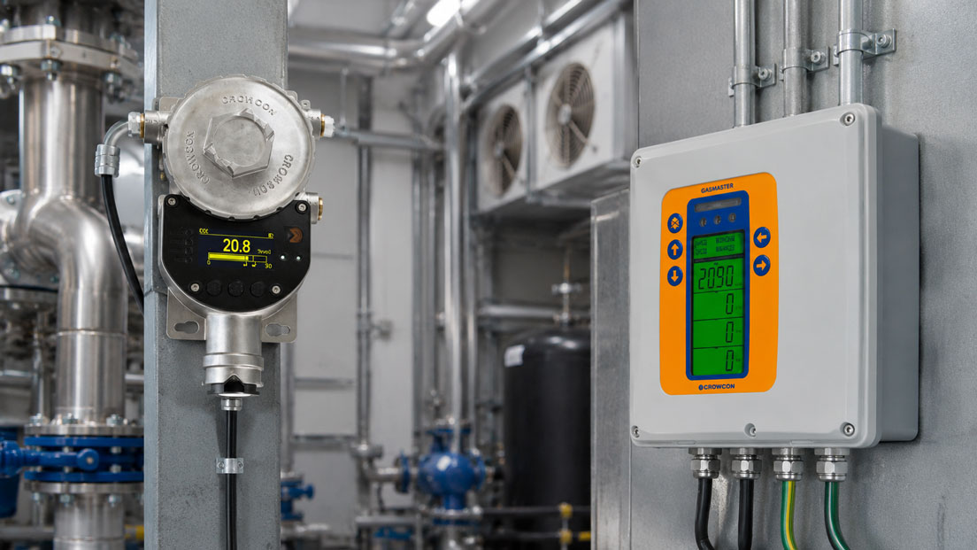
A stationary gas detection system is used when gases need to be monitored permanently and a simple portable gas detector is not sufficient. Typical applications include plant rooms, refrigeration systems, gas storage areas, laboratories, battery rooms, process plants, wastewater treatment plants, boiler rooms, production areas, chemical plants, hazardous areas or areas with oxygen displacement. In these applications, it is not only about detecting a gas, but about a complete safety concept consisting of sensors, measuring points, alarm limits, gas detection control panel, signal transmission, ventilation, shutdown, maintenance and documentation.
The planning of a stationary gas detection system therefore does not begin with the individual gas detector, but with the risk assessment and the specific application. Which gas can escape? Is the gas flammable, toxic or oxygen-displacing? Is it lighter or heavier than air? Where can the gas accumulate? What is the ventilation situation? Which people or plant areas need to be protected? Only from these questions can meaningful sensor positions and alarm strategies be derived.
This article explains what matters when planning stationary gas detection systems. The focus is on gas type, sensor position, gas density, airflow, measuring points, alarm stages, relay outputs, 4–20 mA signals, gas detection control panel, ventilation control, shutdowns, maintenance, calibration, test concept and suitable solutions such as stationary gas detectors and the Gasmaster gas detection control panel.
Table of contents
- Basics: what is a stationary gas detection system?
- Determining the gas type: flammable, toxic or oxygen-changing?
- Planning measuring points: where sensors are truly useful
- Gas density and sensor height: why lighter or heavier than air is decisive
- Considering ventilation, airflow and room geometry
- Defining alarm limits and alarm stages correctly
- Gas detection control panel: collecting, evaluating and forwarding signals
- Relay outputs, 4–20 mA, Modbus and building management system
- Alarm indication, shutdown and organizational measures
- Maintenance, calibration and function test
- Documentation, test concept and traceability
- Typical planning errors in stationary gas detection systems
- Practical example: gas detection system for a refrigeration plant room
- Which measuring instruments / products are suitable?
- Conclusion: a gas detection system is a safety concept, not a single device
- FAQ: frequently asked questions about planning stationary gas detection systems
Basics: what is a stationary gas detection system?
A stationary gas detection system consists of permanently installed gas detectors, an evaluation unit or gas detection control panel and suitable alarm or switching functions. The sensors continuously monitor defined areas. If a specified concentration is exceeded or a critical oxygen value is reached, the system generates an alarm and can trigger further measures.
Unlike portable gas detectors, a stationary gas detection system is not only intended to be carried by a single person. It is part of the technical building or plant safety system. It can continuously monitor rooms, plant areas, gas storage areas, pipeline sections, compressor stations or process sections and forward alarms to central locations.
A complete gas detection system usually comprises several levels. The sensor detects the gas, the transmitter converts the signal into a measured value or output signal, the gas detection control panel evaluates the measured values and the alarm system informs people or controls technical measures. These may include audible sounders, flashing beacons, ventilation control, valve closure, plant shutdown or messages to the building management system.
Correct planning is decisive because an incorrectly positioned or incorrectly parameterized system may react too late or not at all in an emergency. A stationary gas detection system must therefore always match the gas type, room, ventilation, process, alarm strategy and maintenance organization.
| Component | Function | Planning relevance |
|---|---|---|
| Gas detector / sensor | Detects the target gas concentration or oxygen change | Gas type, measuring range, sensor principle and mounting location must match. |
| Gas detection control panel | Collects and evaluates measuring signals | Define number of channels, alarm stages and output functions. |
| Alarm indication | Warns people visually and acoustically | The alarm must be perceived in the right location. |
| Switching functions | Controls ventilation, valves or shutdowns | Define relay logic, alarm stages and safety concept. |
| Documentation | Describes system layout, measuring points, alarm limits and maintenance | Important for operation, inspection, audit and maintenance. |
Determining the gas type: flammable, toxic or oxygen-changing?
The first step in planning is determining the gas type. A gas detection system for flammable gases differs fundamentally from a system for toxic gases or oxygen monitoring. Flammable gases are often evaluated in relation to the lower explosive limit. Toxic gases are usually measured in ppm. With oxygen, monitoring checks whether the oxygen content becomes too low or, in certain applications, too high.
The gas type determines sensor principle, measuring range, alarm limits, mounting position and maintenance strategy. Methane, hydrogen, propane, ammonia, carbon dioxide, carbon monoxide, hydrogen sulfide, refrigerants or solvent vapors behave very differently. Some gases rise upwards, others accumulate close to the floor, while others distribute depending on temperature, ventilation and release point.
The hazard also differs. With flammable gases, the focus is on explosion risk. With toxic gases, the focus is on health hazards for people. With oxygen deficiency, there is a risk of suffocation, for example due to displacement by inert gases or carbon dioxide. A general “gas detection system” without a precise target gas definition therefore cannot be planned sensibly.
In practice, it should be clearly documented for every monitored area which gases or vapors may occur, from which sources they could escape and which limit values or alarm stages are relevant for the operator. Only then can suitable device selection take place.
| Gas type / hazard | Typical examples | Important planning question |
|---|---|---|
| Flammable gases | Methane, propane, hydrogen, solvent vapors | Where can an explosive atmosphere form? |
| Toxic gases | CO, H₂S, NH₃, Cl₂, NO₂ | Where can people be exposed to dangerous concentrations? |
| Oxygen deficiency | Nitrogen, argon, CO₂, inerting | Where can oxygen be displaced? |
| Refrigerants | CO₂, NH₃ or synthetic refrigerants | Where are possible leakage sources and low-lying accumulation areas? |
| Process gases | Industry-specific gases in laboratories, production or process engineering | Which sensor technology is suitable for target gas, cross-sensitivities and environment? |
Planning measuring points: where sensors are truly useful
The position of the sensors is one of the most important points in planning. A sensor can only detect gas where the gas actually reaches it. If a gas detector is mounted in an easily accessible but unfavorable position from an airflow perspective, the system may react too late despite fully functional sensor technology.
Meaningful measuring points are derived from possible leakage sources, gas density, airflow, room geometry, ventilation, temperature and operating states. Sensors are often positioned near valves, flanges, compressors, gas cylinders, pipe connections, refrigeration systems, gas storage areas, process vessels or shafts. At the same time, sensors should not be placed directly in drafts, outside the relevant area or in locations where mechanical damage may occur.
The number of measuring points depends on room size, system structure and risk assessment. A small plant room with one clear leakage source may require fewer measuring points than a branched process area with several potential release points. Large rooms, shielded areas, raised floors, pits or separated plant zones must be considered separately.
A good measuring point is not only meaningful from a measurement perspective, but also maintainable. Gas detectors must be tested, calibrated and, if necessary, replaced. If a sensor is difficult to access, the risk increases that maintenance will be delayed or not carried out properly.
Gas density and sensor height: why lighter or heavier than air is decisive
The density of the gas in relation to air has a major influence on the mounting height of the sensor. Lighter gases tend to rise upwards, while heavier gases can accumulate close to the floor, in pits, shafts or lower-lying areas. Gases with a density similar to air distribute more strongly depending on airflow, temperature and release impulse.
Hydrogen is a typical example of a very light gas. Sensors are often planned in the upper area or near possible accumulation points under the ceiling, provided that room geometry and ventilation confirm this. Propane or many refrigerants, on the other hand, may accumulate closer to the floor. With carbon dioxide, it must also be considered that it can displace oxygen and accumulate in lower-lying areas.
However, gas density alone is not sufficient. Release pressure, temperature, air exchange, ventilation direction, obstacles and heat sources can strongly influence dispersion. A gas may initially escape at high velocity, mix with air and only later stratify according to its density. Sensor height should therefore always be considered in connection with the real application.
For planning, this means that the sensor position must be derived from the possible dispersion behavior of the gas. General mounting heights without considering room, plant and ventilation can lead to incorrect measuring points.
| Gas behavior | Typical tendency | Planning note |
|---|---|---|
| Lighter than air | Gas can accumulate in the upper area | Check sensor position in the upper room area or near the ceiling. |
| Heavier than air | Gas can accumulate close to the floor or in depressions | Evaluate measuring points near the floor, in pits or shafts. |
| Similar to air | Distribution strongly depends on airflow and temperature | Consider ventilation and release point particularly carefully. |
| Released under pressure | Gas jet can initially be carried far | Plan sensor not only according to density, but also according to release direction. |
| In cold or warm environment | Temperature influences stratification and dispersion | Include process and room temperature in the evaluation. |
Considering ventilation, airflow and room geometry
Ventilation influences how a gas distributes in the room and how quickly a sensor detects a leak. Strong ventilation can dilute gas, but it can also carry it away from the sensor. Poor ventilation can lead to dangerous accumulation, especially in corners, shafts, suspended ceilings, raised floors or lower-lying areas.
During planning, it should therefore be assessed where supply air enters, where extract air is removed and which airflows occur during normal operation. Operating states are also important: does the ventilation run continuously or only when required? Is it increased in the event of an alarm? Are there failures or maintenance states? Are doors opened or closed? All these factors can influence gas distribution.
A sensor directly in front of a strong extract opening can be useful if representative room air is detected there. However, it can also be unfavorable if gas from another direction does not reach it in time. Conversely, a sensor in a calm corner may react too late if the leak occurs in a strongly ventilated area.
Room geometry is also relevant. Large rooms, angled areas, enclosures, machine housings, suspended ceilings or pits can require separate measuring points. A gas detection system should therefore be planned not only in the floor plan, but also in height and within the airflow concept.
Defining alarm limits and alarm stages correctly
Alarm limits define the concentration from which a gas detection system reacts. Several alarm stages are often used. A first alarm stage can trigger a pre-alarm or technical measure, for example switching on ventilation or sending a message to the building management system. A second alarm stage can trigger stronger measures, such as audible alarm indication, evacuation, valve closure or plant shutdown.
The alarm limits depend on gas type, hazard, application and operational requirements. For flammable gases, reference is often made to the lower explosive limit. For toxic gases, occupational exposure limits, short-term values or plant-specific limit values are usually in focus. For oxygen monitoring, limits for oxygen deficiency or oxygen enrichment are relevant.
It is important that alarm limits are not selected arbitrarily. They must match the risk assessment, the response time of the system and the intended measures. An alarm limit that is too low can lead to frequent false alarms. An alarm limit that is too high may react too late. Delay times and alarm acknowledgement must also be considered carefully.
Alarm stages should also be clearly named and understood organizationally. If Alarm 1 is triggered, it must be clear who is informed and what happens. If Alarm 2 is triggered, the measures must also be clear. A gas detection system is only effective if the technical alarms are translated into understandable actions.
| Alarm stage | Typical function | Possible measure |
|---|---|---|
| Pre-alarm | Early detection of a developing leak | Message to BMS, local display, increased attention. |
| Alarm 1 | Technical reaction or operational warning | Switch on ventilation, activate signal devices, inform personnel. |
| Alarm 2 | Critical condition or escalation | Shut down system, close valve, evacuate area. |
| Fault | Sensor, cable or control panel not functional | Trigger maintenance and check substitute measures. |
| Maintenance mode | Testing or calibration is being carried out | Suppress alarms in a controlled way or identify them separately. |
Gas detection control panel: collecting, evaluating and forwarding signals
A gas detection control panel is the central element when multiple gas detectors need to be monitored and alarms processed in an organized way. It receives the sensor signals, displays measured values or status information and switches outputs for alarm indication, ventilation, shutdowns or external messages.
When selecting a gas detection control panel, the number of channels, expandability, display, alarm stages, relay outputs, power supply, fault messages, event memory and interfaces are important. In small systems, a compact control panel may be sufficient. In larger systems, several measuring points, different gases and various alarm zones must be managed.
The control panel must match the signal type of the sensors. Many stationary gas detectors provide analog 4–20 mA signals or digital signals. The gas detection control panel must evaluate these correctly and assign them clearly to the measuring points. In addition, it should be clear which relays switch at which alarm stage and whether they should be latching, non-latching, de-energized or energized in normal condition.
A good gas detection control panel also simplifies operation and maintenance. It displays faults, supports assignment of measuring points and, depending on the version, can store events. This is important for operators because alarms, faults and maintenance events must be traceable later.
Relay outputs, 4–20 mA, Modbus and building management system
Stationary gas detection systems must be able to forward their information to other systems. Relay outputs are frequently used to control signal devices, ventilation systems, valves, shutdowns or fault messages. It must be precisely defined which relay switches at which alarm stage and what effect it has.
Analog 4–20 mA signals are widely used in industrial applications. They can transmit measured values from gas detectors to a gas detection control panel, PLC or building management system. Measuring range, scaling, fault current, cable length and power supply must be designed correctly. An incorrectly scaled input can cause the control panel or controller to interpret an incorrect gas value.
Digital interfaces such as Modbus can be useful when several measured values, status information or diagnostics need to be transmitted. Addresses, registers, baud rate, data format and communication monitoring must be documented properly. Digital communication does not automatically replace a well-thought-out alarm strategy.
The UPS4E loop calibrator is helpful for testing 4–20 mA signals. It can be used to measure or simulate current loops and detect scaling errors between gas detector, gas detection control panel, PLC and control system. This is particularly important during commissioning and troubleshooting because sensor, control panel and controller must interpret the same measured value in the same way.
| Signal / output | Typical use | What to pay attention to? |
|---|---|---|
| Relay output | Alarm, ventilation, valve, shutdown, fault | Define switching logic, latching behavior, fail-safe principle and alarm stage. |
| 4–20 mA | Measured value transmission to control panel, PLC or BMS | Check measuring range, fault current, load and scaling. |
| Modbus / digital interface | Transmit several measured values and status information | Document address, registers, data format and communication monitoring. |
| Audible signal device | Warning of people in the area | Check audibility despite machine noise and spatial separation. |
| Visual alarm indication | Warning light, beacon or display | Ensure visibility at entrances and in the hazardous area. |
Alarm indication, shutdown and organizational measures
A gas detection system detects and reports a hazard. To turn this into safety, suitable measures must follow. These measures can be technical, organizational or both. Technical measures include, for example, increasing ventilation, closing valves, shutting down systems, shutting off a gas supply or forwarding a message to a control room.
Organizational measures concern how people respond. Who reacts to an alarm? Who is allowed to enter the area? When is evacuation required? Who resets the system? Which substitute measures apply in the event of a fault or during maintenance? Such questions must be clarified before commissioning so that there is no uncertainty in an emergency.
The alarm indication must be perceived where people need to react. A beacon in the plant room may not be sufficient if nobody is normally present there. Conversely, an audible alarm may be missed in a noisy environment. Signal devices, displays and messages should therefore match the operating process.
Fault behavior is particularly important. A defective sensor, interrupted cable or failed control panel must not go unnoticed. Fault messages are therefore part of the safety function and should be taken just as seriously as gas alarms.
Maintenance, calibration and function test
Stationary gas detectors must be checked and maintained regularly. Sensors age, can become contaminated, drift or be influenced by environmental conditions. Depending on sensor principle, gas type and operating environment, maintenance intervals and calibration requirements can vary.
Maintenance includes visual inspection, functional test, gas challenge with test gas, calibration, testing of alarm forwarding and checking of switching functions. It is not enough to simply look at the display of the control panel. The entire chain from sensor to alarm indication or shutdown must be considered.
During a function test, it should be clear whether only the sensor is being tested or whether the entire alarm chain including relays, ventilation and signal devices is being tested. In some systems, switching functions must be suppressed or bypassed in a controlled manner during maintenance so that unintended shutdowns do not occur. Such states must be clearly identified and documented.
Maintenance should be carried out by qualified personnel. Suitable test gases, appropriate adapters, documented test values and clear evaluation criteria are important. Without regular maintenance, a gas detection system may become unreliable in an emergency, even though it appears ready for operation from the outside.
Documentation, test concept and traceability
A stationary gas detection system should be fully documented. This includes target gases, measuring ranges, sensor positions, mounting heights, alarm limits, relay functions, circuit diagrams, wiring, zones, maintenance intervals, calibration data and responsibilities. This documentation is important not only for commissioning, but also for later operation and modifications.
Especially with several measuring points, it must be clearly traceable which sensor monitors which area and which action is triggered by which alarm. An unclear assignment can lead to wrong decisions in the event of an alarm. Clean measuring point identification is also indispensable for maintenance and troubleshooting.
The test concept should define how often sensors are tested, which test gases are used, which tolerances apply and how alarms are tested. It should also define how sensor faults, maintenance mode, disabled relays or measuring points taken out of service are handled.
Changes to the system should also be documented. If a gas detector is moved, an alarm value is changed or a relay is assigned differently, this change must be traceable in the plan, in the control panel and in the operating documentation. Otherwise, the gas detection system loses transparency over time.
Typical planning errors in stationary gas detection systems
A common error is selecting a gas detector without clearly considering the gas type and measuring location. A sensor may technically be suitable for a gas, but be mounted in the wrong place. It may then detect a leak too late or not at all. Sensor position and gas behavior are therefore just as important as the detector data sheet.
Another error is neglecting ventilation. If a sensor is mounted without considering airflow, supply air, extract air and room geometry, gas distribution may be misjudged. Especially in plant rooms, laboratories and refrigeration systems, ventilation can determine where a dangerous concentration forms first.
Alarm limits are also sometimes not considered carefully enough. Limits that are too low can lead to frequent false alarms that are later ignored. Limits that are too high can react too late in an emergency. Alarm limits must therefore match the hazard, sensor, response time and planned measures.
An unclear relay and alarm matrix is also problematic. If it is not clearly defined which relay switches for which sensor and which alarm stage, errors occur during commissioning and maintenance. A gas detection control panel is only as good as the well-designed assignment of its inputs and outputs.
| Error pattern | Possible cause | Test approach |
|---|---|---|
| Sensor detects leak too late | Incorrect mounting height or unfavorable measuring point | Reassess gas density, leakage source and airflow. |
| Frequent false alarms | Alarm limit too low, cross-sensitivity or process disturbance | Check alarm values, sensor principle and operating states. |
| Alarm is not noticed | Signal device in wrong location or too quiet | Check alarm indication from the perspective of affected people. |
| Ventilation does not start | Relay assignment, wiring or control logic faulty | Test alarm matrix and switching chain. |
| Measured value in BMS is incorrect | 4–20 mA scaling or data point parameterized incorrectly | Check signal path with loop calibrator. |
Practical example: gas detection system for a refrigeration plant room
A plant room contains a refrigeration system with several compressors, pipe connections and service valves. The operator wants to install a stationary gas detection system because refrigerant can escape in the event of a leak and, depending on the medium, accumulate in certain areas. In addition, the ventilation should be automatically increased in the event of an alarm and a message sent to the building management system.
During planning, the refrigerant used is considered first. Possible leakage sources are then identified. The sensor positions are selected so that critical accumulation areas and relevant plant components are monitored. Mounting height, airflow, room geometry and maintenance access are taken into account.
The gas detectors are connected to a gas detection control panel. Alarm 1 starts the ventilation and sends a message to the BMS. Alarm 2 additionally activates a visual and audible warning at the entrance to the plant room and can trigger further measures depending on the safety concept. Sensor faults are reported separately so that a failure does not go unnoticed.
During commissioning, not only the sensor values are checked. 4–20 mA signals, relay outputs, alarm lights, signal devices, BMS messages and maintenance mode are also tested. Measuring points, alarm limits and relay functions are documented. This creates a gas detection system that does not merely install sensors, but represents a traceable safety concept.
Which measuring instruments / products are suitable?
The category stationary gas detectors is the right starting point when gas detectors are to be permanently installed in plant rooms, laboratories, refrigeration systems, process plants, storage areas or industrial areas. Depending on gas type and application, different sensor types, measuring ranges and output signals may be suitable.
The Gasmaster gas detection control panel is suitable for systems in which several gas detectors need to be centrally monitored and alarms processed in a structured way. It is particularly interesting when measured values, alarm stages, relay outputs, faults and external messages are to be combined in one common system.
For larger or more complex projects, the category gas detection system may also be relevant. This focuses more on the combination of sensor technology, control panel, alarm indication and system design. Such an approach is useful when operators need not only individual sensors, but a complete gas detection concept.
If stationary gas detectors are integrated via 4–20 mA, the UPS4E loop calibrator is a helpful test tool. It enables commissioning engineers and service technicians to test whether sensor, gas detection control panel, PLC or BMS use the same scaling and whether the signal path works correctly.
| Product / area | Typical use | Particularly relevant for |
|---|---|---|
| Stationary gas detectors | Permanent gas detection at fixed measuring points | Plant rooms, laboratories, refrigeration systems, gas storage areas and process plants |
| Gasmaster gas detection control panel | Central evaluation and alarm indication for multiple gas detectors | Multiple measuring points, alarm stages, relay outputs and BMS integration |
| Gas detection system | System view consisting of sensors, control panel and alarm indication | Project business, operator concepts and safety-related plant planning |
| Visual and audible signal devices | Warning people in the hazardous area | Entrances, plant rooms, noisy environments and evacuation concepts |
| UPS4E loop calibrator | Testing and simulation of 4–20 mA signals | Commissioning, troubleshooting, scaling check and signal comparison |
Conclusion: a gas detection system is a safety concept, not a single device
A stationary gas detection system cannot be planned solely by selecting a gas detector. What matters is the interaction of gas type, measuring point, sensor position, alarm limit, gas detection control panel, output signals, alarm indication, ventilation, shutdown, maintenance and documentation. Only when these points fit together does an effective safety solution emerge.
The correct measuring point planning and a clear alarm strategy are particularly important. Sensors must be installed where gas can realistically occur or accumulate. Alarm stages must be clearly defined and trigger specific technical or organizational measures. The gas detection control panel must reliably evaluate the signals and switch the correct outputs.
The most important recommendation is: always plan stationary gas detection systems on a project-specific basis. Target gas, room, leakage sources, ventilation, presence of people, alarm indication and maintenance must be considered together. This turns individual gas detectors into a traceable and reliable gas detection system.
FAQ: frequently asked questions about planning stationary gas detection systems
What is a stationary gas detection system?
A stationary gas detection system is a permanently installed system for continuous monitoring of gases or oxygen changes. It consists of sensors, evaluation unit or gas detection control panel and alarm or switching functions.
When is a stationary gas detection system useful?
It is useful when gases can occur continuously or become dangerous in the event of leaks, for example in plant rooms, laboratories, refrigeration systems, gas storage areas, process plants or battery rooms.
What is the difference compared to portable gas detectors?
Portable gas detectors are carried by people and are often used for personal protection. Stationary gas detectors are permanently installed and continuously monitor defined areas.
Which gas types can be monitored?
Depending on sensor technology, flammable gases, toxic gases, oxygen deficiency, oxygen enrichment, refrigerants or process gases can be monitored. The selection depends on target gas and application.
Why is the gas type so important for planning?
The gas type determines sensor principle, measuring range, alarm limits, mounting height and maintenance requirements. Without a clear target gas definition, no meaningful gas detection system can be planned.
Where should gas detectors be installed?
Gas detectors should be installed where gas can realistically escape, pass by or accumulate. Leakage sources, gas density, ventilation, room geometry and maintenance access must be considered.
Why does gas density matter?
Light gases tend to rise upwards, while heavy gases tend to accumulate lower down. Sensor height must therefore match the dispersion behavior of the gas.
Is one sensor per room sufficient?
That depends on room size, gas type, ventilation, leakage sources and room geometry. In small, clearly structured rooms, one sensor may be sufficient; in larger or angled areas, several measuring points may be necessary.
What does a gas detection control panel do?
A gas detection control panel collects the signals from gas detectors, evaluates measured values and faults and switches outputs for alarm indication, ventilation, shutdown or forwarding to other systems.
Which alarm stages are common?
Often there is a pre-alarm or Alarm 1 and a higher alarm stage such as Alarm 2. In addition, there are fault messages and maintenance states. The exact function must be defined on a project-specific basis.
What can be switched automatically in the event of an alarm?
Possible options include ventilation, valves, plant shutdowns, visual and audible signal devices, messages to the building management system or control room, and fault messages.
Why are relay outputs important?
Relay outputs enable simple switching functions in the event of an alarm or fault. They can control ventilation, warning lights, signal devices, valves or controller inputs.
What role does 4–20 mA play?
4–20 mA is frequently used for analog measured value transmission from gas detectors to the control panel, PLC or building management system. Scaling, fault current and signal path must be set correctly.
When is Modbus useful?
Modbus can be useful when multiple measured values, status information or diagnostics are to be transmitted digitally. Address, registers and data format must be documented properly.
How are 4–20 mA signals tested?
A loop calibrator can be used to measure or simulate the signal path. This makes it possible to detect scaling errors between sensor, control panel, PLC and control system.
How often does a gas detection system need maintenance?
This depends on sensor principle, gas type, operating environment, manufacturer specifications and operator requirements. Regular function tests and calibrations are decisive for reliable operation.
What belongs in the documentation of a gas detection system?
Target gas, measuring range, sensor position, mounting height, alarm limits, relay functions, wiring, maintenance intervals, calibration data and responsibilities should be documented.
What is the most common planning error?
Sensors are often installed based on good accessibility, but not according to gas behavior, leakage source and airflow. As a result, a leak may be detected too late.