


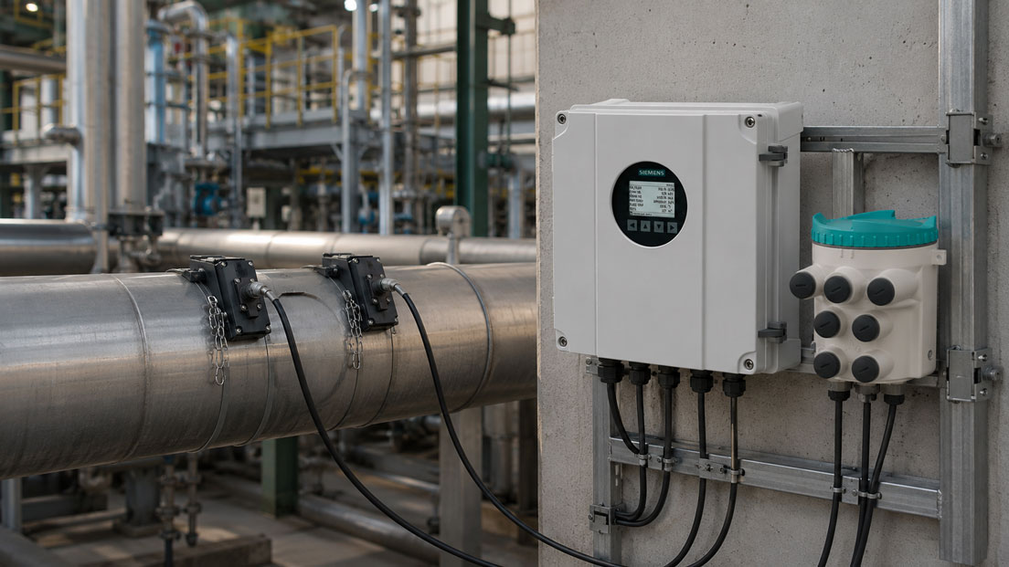
Flow measurements in potentially explosive atmospheres place special requirements on technology, planning and operation. In chemical plants, refineries, oil and gas applications, process plants, tank farms, energy plants or with demanding media, measurement accuracy is often not the only decisive factor. Explosion protection, safe installation, minimal intervention in existing pipelines, suitable sensor positions and clean integration into process automation are just as important.
Clamp-on ultrasonic flow measurement offers a particular advantage in such applications: the sensors are mounted externally on the pipe. The medium remains inside the pipe, the line does not have to be opened and no additional pressure loss is created. Especially in existing plants, large pipelines, difficult media or hazardous areas, this non-invasive measurement technology can be a very interesting alternative to inline modifications.
This article explains when the SITRANS FS230 is useful in hazardous areas and what should be considered during planning. The focus is on clamp-on technology, Ex requirements, the FST030/FSS200 system, SITRANS FS-DSL, installation without media contact, advantages compared with inline modifications, measuring point planning, pipe data, signal quality, process conditions, 4–20 mA signals, diagnostics and suitable areas of application in the process industry.
Table of contents
- Basics: What does clamp-on ultrasonic flow measurement mean?
- Hazardous areas: Why flow measurement must be planned especially carefully there
- SITRANS FS230: System design with FST030, FSS200 and FS-DSL
- Advantages compared with inline modifications in existing plants
- Typical applications in chemicals, oil/gas and the process industry
- Planning the measuring point: pipe data, installation position and sensor location
- Assessing medium, pipe material and signal quality
- Single-path or multi-path measurement: when additional measuring paths make sense
- Integration into process control systems: 4–20 mA, digital signals and diagnostics
- Maintenance, inspection and operation in demanding plants
- Typical errors in clamp-on measurements in hazardous areas
- Practical example: retrofitting flow measurement in a chemical plant
- Which measuring instruments / products are suitable?
- Conclusion: SITRANS FS230 makes sense when explosion protection and retrofit capability come together
- FAQ: Frequently asked questions about ultrasonic flow measurement in hazardous areas
Basics: What does clamp-on ultrasonic flow measurement mean?
In clamp-on ultrasonic flow measurement, ultrasonic sensors are mounted externally on the pipeline. The sensors transmit and receive ultrasonic signals through the pipe wall and the medium. The flow velocity is calculated from the transit time difference between the signals travelling with and against the flow direction. Together with the internal pipe diameter and other parameters, this produces the volume flow rate.
The key difference compared with inline flowmeters is that no measuring device has to be installed inside the pipeline. There is no direct media contact, no additional process seal, no restriction of the pipe cross-section and no additional pressure loss caused by the measuring device. This makes clamp-on measurements particularly interesting for retrofits, temporary measurements and applications where intervention in the pipeline is difficult or undesirable.
In hazardous areas, this advantage is especially relevant. Any mechanical change to a pipeline can trigger additional approvals, shutdowns, leak tests, welding work, explosion protection assessments and documentation. An externally mounted measurement can significantly reduce the effort, provided that the pipeline, medium, Ex concept and measurement requirement are suitable for clamp-on technology.
However, clamp-on is not simply an “attach and done” technology. Reliable measured values require careful assessment of pipe data, wall thickness, material, medium, temperature, installation position, sensor spacing, signal quality and flow profile. Measurement quality strongly depends on whether stable sound transmission through the pipe wall and medium is possible.
| Characteristic | Meaning with clamp-on | Practical relevance |
|---|---|---|
| External mounting on the pipe | Sensors have no direct media contact | Advantage with aggressive, hazardous or hard-to-access media. |
| No pipe separation | The pipeline does not have to be cut open | Interesting for retrofitting and plants with limited shutdown windows. |
| No pressure loss | No components are installed in the flow cross-section | Advantage for energy-critical and process-critical lines. |
| Pipe data required | Outer diameter, wall thickness and material must be known | Basis for correct parameterization and sensor positioning. |
| Signal quality depends on the application | Medium, pipe condition and installation influence the ultrasonic signal | The measuring point must be technically assessed in advance. |
Hazardous areas: Why flow measurement must be planned especially carefully there
In potentially explosive atmospheres, only suitable devices and installation concepts may be used. This is not only about the sensor itself, but about the entire measuring point. Transmitter, sensors, connection modules, cables, grounding, mounting location, zone, temperature class, type of protection and documentation must match the plant’s explosion protection concept.
During planning, it must first be clear in which zone the sensors will be installed and where the transmitter may be mounted. In many plants, it is useful to install sensitive or operator-relevant electronics outside the most critical area and place only the necessary components in the hazardous area. This is exactly where the system architecture becomes important.
A clamp-on measurement can be mechanically advantageous because the pipe is not opened. Nevertheless, it does not replace an Ex assessment. Externally mounted sensors, electronic modules and cables are also located in the potentially explosive atmosphere if installed there. Therefore, the approved versions and installation conditions must be observed precisely.
Ambient temperature, process heat, pipe insulation, mechanical protection and accessibility also play a role. A sensor that is favorable from a measurement perspective must also remain safely mounted, protected and maintainable. In hazardous areas, measuring points should therefore be coordinated early with process engineering, electrical engineering, explosion protection, maintenance and the operator.
| Ex planning point | Why relevant? | Typical question |
|---|---|---|
| Zone | Determines the requirements for devices and installation | In which zone are the sensor, electronic module and cables located? |
| Device version | Only suitable Ex versions may be used | Is the selected version suitable for the intended area? |
| Transmitter mounting location | Operation and electronics may be more practical outside critical areas | Where can the FST030 be mounted safely and accessibly? |
| Cable route | Signal and supply must be routed safely | How do sensor cables and the connection to the control system run? |
| Documentation | Ex installations require traceable documentation | Are certificates, nameplates, wiring diagrams and mounting locations documented? |
SITRANS FS230: System design with FST030, FSS200 and FS-DSL
The SITRANS FS230 is a clamp-on ultrasonic flow measurement system for demanding industrial applications. The system consists of the SITRANS FST030 transmitter and the FSS200 clamp-on sensors. Depending on the application, the system can be supplemented with an external SITRANS FS-DSL electronic module that is installed close to the sensors.
This system architecture is particularly interesting for hazardous areas. The transmitter can be mounted in a suitable location, while the sensor technology and external electronics are positioned closer to the measuring point. This allows the measuring point to be integrated more flexibly into the Ex and plant concept. At the same time, the measuring signal is conditioned or digitized early, which can provide advantages for signal quality and transmission in demanding applications.
The FSS200 sensors are mounted externally on the pipe and aligned to match the pipeline. Parameterization requires, among other things, pipe diameter, wall thickness, pipe material, medium and process conditions. Only when these data are correct can the system calculate the sensor spacing and measurement correctly.
The SITRANS FS230 is particularly useful when a high-quality, permanently installed clamp-on solution is required and the application places higher demands on accuracy, diagnostics, Ex suitability, multi-path capability or process integration. For simple temporary checks, a mobile solution may be sufficient; for demanding stationary Ex applications, a system such as FS230 is much more suitable.
Advantages compared with inline modifications in existing plants
Inline flowmeters are very suitable for many applications, but they require intervention in the pipeline. In existing Ex plants, exactly this intervention can be complex. The line may have to be emptied, flushed, approved, opened, modified, tested and put back into operation. With hazardous, flammable or toxic media, this effort can be considerable.
Clamp-on technology avoids this direct intervention in the process. The sensors are mounted externally, so the pipeline remains closed. This means retrofits, additional measuring points, energy or process optimizations and measurements on hard-to-access media can often be implemented much more easily. This can be economically very interesting, especially for large nominal diameters.
Another advantage is that no additional component sits in the flow cross-section. There is no additional pressure loss and no wetted measuring point that could wear, corrode or become contaminated. With aggressive, hot, hazardous or valuable media, this can be an important advantage.
At the same time, the benefit should not be overestimated. Clamp-on measurements require a suitable pipeline and a sufficiently good ultrasonic signal. Heavily corroded pipes, unknown wall structures, unfavorable coatings, multiphase media or high gas bubble content can make measurement more difficult. The decision should therefore always be derived from the application and measurement objective.
| Criterion | Clamp-on ultrasonic | Inline flow measurement |
|---|---|---|
| Installation effort | Mounted externally on the existing pipeline | Pipeline must be mechanically modified. |
| Media contact | No direct contact with the medium | Measuring device is wetted. |
| Pressure loss | No additional pressure loss caused by the measuring device | Possible depending on measuring principle and installation. |
| Retrofitting | Very interesting for existing plants | Often associated with shutdown and modification. |
| Dependence on pipe | Pipe data and pipe condition are decisive | Pipe condition before and after the measuring device also remains relevant, but sensor technology is installed in a defined way. |
Typical applications in chemicals, oil/gas and the process industry
Ultrasonic flow measurement with clamp-on technology is particularly interesting when the process should not be opened or when existing pipelines must be monitored retrospectively. In the chemical industry, this can include product lines, solvent circuits, cooling or heating circuits, auxiliary media, filling areas or distribution networks. In oil and gas applications, lines with hydrocarbons, auxiliary media, water, condensate or process gases may be relevant.
In the process industry, clamp-on systems are often used when operators need additional transparency about flow rates without complex process modifications. This can help with energy optimization, balancing, pump monitoring, leak detection, plant comparison, production analysis or temporary verification of existing measuring points.
Hazardous areas do not only occur with classic flammable gases. Solvent vapors, flammable liquids, dust or gas mixtures, tank areas or certain process zones can also create corresponding requirements. Flow measurement must therefore always be considered together with Ex zone classification and the safety concept.
The SITRANS FS230 is especially interesting when the task is not a simple orientation measurement, but a robust stationary solution with industrial integration, diagnostic options and suitable system architecture for demanding applications. In project business and process plants, it is not only the measured value that matters, but the long-term operational reliability of the measuring point.
Planning the measuring point: pipe data, installation position and sensor location
Successful clamp-on measurement begins with measuring point planning. Accurate pipe data are required: pipe outer diameter, wall thickness, pipe material, lining or coating, medium, temperature, pressure and expected flow range. These data determine whether the ultrasonic signals can be transmitted reliably through the pipe wall and medium.
The sensor position should be in a section where the flow profile is as stable as possible. Directly downstream of pumps, control valves, sharp pipe bends, T-pieces, reducers or internal fittings, the flow may be disturbed. Such disturbances affect measurement because ultrasonic flowmeters infer the flow rate from the local flow velocity.
The mechanical installation situation must also be suitable. The sensors must be securely mounted on the pipe. Pipe insulation may have to be considered in the sensor area. For hot or cold lines, outdoor installations, vibrations or mechanical stress, mounting accessories and protective measures must suit the environment.
In hazardous areas, the measuring point must also be safely accessible. Maintenance, inspection and readjustment must not unnecessarily endanger personnel. At the same time, the installation must be carried out so that sensors, cables and electronic modules are protected from mechanical damage.
| Planning data | Why required? | Effect on measurement |
|---|---|---|
| Pipe outer diameter | Basis for sensor spacing and pipe geometry | Incorrect input leads to incorrect flow calculation. |
| Wall thickness | Influences the sound path through the pipe | Important for signal quality and parameterization. |
| Pipe material | Determines sound propagation in the pipe | Relevant for transit time and sensor position. |
| Medium | Sound velocity and attenuation depend on the medium | Liquids, oils and gases must be assessed correctly. |
| Flow profile | Disturbed flow influences the measured value | Observe inlet runs and position relative to fittings. |
Assessing medium, pipe material and signal quality
Clamp-on measurement requires a sufficiently stable ultrasonic signal. This signal is influenced by the sensor, coupling, pipe wall, medium and flow. Media with good sound transmission are easier to measure than media with strong attenuation, gas bubbles, solids content or changing properties.
For liquids, ultrasonic clamp-on can often be used very effectively if the pipeline is suitable and the medium is not too disturbed. With oils, solvents, water, cooling media or process liquids, the technology can be very interesting. For gases, the application depends more strongly on pressure, medium, pipe data and signal conditions.
Pipe material and pipe condition are equally important. Steel, stainless steel, plastic or lined pipes have different acoustic properties. Corrosion, coatings, deposits, unclear wall thicknesses or multi-layer pipe systems can make measurement more difficult. The measuring point should therefore be as well known and documented as possible.
Signal quality should be evaluated and documented during commissioning. Modern systems provide diagnostic information that helps assess sensor position and signal stability. Especially in Ex and process plants, this diagnosis is important because later deviations in signal quality or measured value can indicate process changes, mounting problems or sensor condition.
Single-path or multi-path measurement: when additional measuring paths make sense
Depending on the system and application, ultrasonic flow measurements can be carried out with one or several measuring paths. One measuring path can be sufficient for many applications if pipeline, flow profile and measurement requirements match. Multi-path measurements can be useful when higher requirements for accuracy, repeatability or flow profile assessment exist.
In large pipelines, demanding process conditions or non-ideal inlet runs, a multi-path solution can offer advantages. It records the flow at several points and can therefore enable a more robust evaluation of the flow rate. This is particularly interesting when the measuring point is to be used permanently for process control, balancing or monitoring.
However, the effort increases with the number of measuring paths. More sensors mean more installation, more cable routing, more parameterization and more documentation. In hazardous areas, additional components must also fit into the Ex concept. Therefore, the number of measuring paths should be derived from the measurement task and not simply selected as high as possible.
The key question is: what measurement uncertainty is permissible and how critical is the flow value for operation? If the measured value is only used for trend monitoring, a simple solution may be sufficient. If it is used for balancing, process control or safety-related decisions, a more complex measuring point configuration may be sensible.
Integration into process control systems: 4–20 mA, digital signals and diagnostics
Stationary flow measurements in hazardous areas are usually integrated into a process control system, PLC, energy monitoring system or operating data acquisition system. For this, output signal, measuring range, unit, scaling, fault behavior and diagnostic information must be clearly defined.
An analog 4–20 mA signal remains a very important standard in many process plants. It must be clearly defined which flow value corresponds to 4 mA and which to 20 mA. In addition, it should be defined how faults are signaled and how the control system interprets this information. Incorrect scaling can cause a correctly measuring device to generate incorrect values in the control system.
Digital communication and diagnostic functions can offer additional advantages. They provide access to status information, signal quality, device condition or further process values. Especially with clamp-on measurements, diagnostics are helpful because signal quality and measuring point condition provide important information about measurement reliability.
The UPS4E loop calibrator is suitable for testing 4–20 mA signals. It can be used to measure or simulate current loops and detect scaling errors between flowmeter, display, PLC and control system. During commissioning and troubleshooting, this is particularly important because the measuring instrument and control system must interpret the same flow value in the same way.
| Integration | Typical function | What to pay attention to? |
|---|---|---|
| 4–20 mA | Analog transmission of the flow value | Check measuring range, unit, fault current and scaling. |
| Relay / limit value | Alarm or switching function at limit value | Clearly define switching logic and process response. |
| Digital communication | Measured values, diagnostics and device status | Document addressing, data points and diagnostic evaluation. |
| Local display | Control at the transmitter | Consider operability and mounting location in the Ex concept. |
| Signal testing | Comparison between device and control system | Check current loop or data point during commissioning. |
Maintenance, inspection and operation in demanding plants
Clamp-on ultrasonic measurements have no wetted moving parts and cause no pressure loss. Nevertheless, they must be checked regularly during operation. Sensor mounting, coupling, cables, electronic modules, signal quality, parameterization and diagnostic values should be considered as part of maintenance.
In hazardous areas, it is additionally important that inspection and maintenance work is carried out according to applicable operational requirements. Components must not be opened, modified or replaced arbitrarily. Spare parts, cable glands, mounting accessories and documentation must match the Ex version. After changes to pipe insulation or the pipeline itself, it should also be checked whether the measuring point still works correctly.
With clamp-on sensors, mechanical fastening can play a role over the long term. Vibrations, temperature changes or work on the pipeline can influence the position. If the sensor position or coupling changes, signal quality can decrease. Modern diagnostic values help detect such changes at an early stage.
A clear maintenance strategy is important for operators. It should be defined which diagnostic values are checked, when a visual inspection takes place, how signal testing is performed and which measures are necessary if values are conspicuous. This keeps the measuring point traceable and operationally reliable in the long term.
Typical errors in clamp-on measurements in hazardous areas
A common error is selecting a clamp-on system without complete pipe data. If outer diameter, wall thickness, material or lining are only estimated, parameterization may be incorrect. This leads to implausible measured values or poor signal quality.
Another error is an unfavorable sensor position. Directly after fittings, pumps, bends or disturbances, the flow profile may be so uneven that the measurement is not representative. Mounting on damaged, heavily corroded or poorly accessible pipe sections can also be problematic.
In hazardous areas, sometimes only the sensor and measuring instrument are considered, but not the entire installation concept. Cable routes, electronic modules, mounting accessories, zone, documentation and maintenance access must also fit. A technically functioning measurement is not automatically a correctly planned Ex measuring point.
Signal processing can also cause errors. If the 4–20 mA output, unit or scaling does not match the PLC, the values in the control system will not be correct. Therefore, the measuring chain from sensor to display or process control system should be checked.
| Error pattern | Possible cause | Test approach |
|---|---|---|
| Measured value is implausible | Incorrect pipe data or incorrect parameterization | Check pipe diameter, wall thickness, material and medium. |
| Signal quality is poor | Unfavorable pipe location, poor coupling or unsuitable medium | Assess sensor position, coupling and diagnostic values. |
| Measured value fluctuates strongly | Disturbed flow profile, air/gas content or process instability | Check inlet run, fittings and process condition. |
| Ex documentation is incomplete | Components, zone or cable route not properly documented | Update Ex concept, nameplates and documents. |
| Control system value is incorrect | 4–20 mA scaling or data point incorrectly set | Check signal path with a loop calibrator. |
Practical example: retrofitting flow measurement in a chemical plant
In a chemical plant, the flow rate of an existing product line in a hazardous area is to be monitored. The line can only be opened with great effort because approval, draining, flushing, shutdown and subsequent leak testing would be required. The operator is therefore looking for a solution that can be retrofitted without intervention in the pipeline.
During planning, medium, pipe data, wall thickness, pipe material, temperature, pressure and expected flow range are checked first. The Ex zone is also assessed. The sensor position is selected on the straightest possible pipe section that is easily accessible and has sufficient distance from a control valve.
The SITRANS FS230 is specified as a stationary clamp-on system. The FSS200 sensors are mounted externally on the pipe. The transmitter is positioned so that operation, maintenance and Ex concept fit together. If required, the external FS-DSL module is used close to the sensor technology to integrate the measuring point appropriately into the plant.
During commissioning, sensor spacing, signal quality, diagnostic values and flow display are checked. The 4–20 mA signal is also compared with the PLC. The measuring point, pipe data, Ex-relevant components and signal assignment are documented. This creates a retrofitted flow measurement without opening the pipeline or installing an additional wetted measuring point.
Which measuring instruments / products are suitable?
The SITRANS FS230 is the central solution for demanding clamp-on ultrasonic flow measurements in industrial applications and hazardous areas. The system is particularly interesting when flow on existing pipelines is to be recorded permanently without touching the medium or mechanically modifying the pipeline.
The category Siemens ultrasonic flow measurement provides an overview of ultrasonic solutions for process applications. It is the right starting point when distinguishing between clamp-on and inline ultrasonic, mobile and stationary solutions or different Siemens systems.
For general applications, the category ultrasonic flowmeters is also relevant. It covers non-contact, inline or retrofit flow measurement for liquids and selected gases. Depending on the application, other ultrasonic measuring systems may also be useful.
If the SITRANS FS230 or another flowmeter is integrated into a PLC, display or control system via 4–20 mA, the UPS4E loop calibrator is a helpful test instrument. It can be used to measure or simulate current loops and detect scaling errors between measuring instrument and control system.
| Product / area | Typical use | Particularly relevant for |
|---|---|---|
| SITRANS FS230 | Stationary clamp-on ultrasonic flow measurement | Hazardous areas, chemicals, oil/gas, process industry, retrofitting and demanding measuring points |
| FST030 / FSS200 system | Transmitter and clamp-on sensor technology for FS230 | Permanent installation, diagnostics, signal quality and industrial process integration |
| SITRANS FS-DSL | External electronic module close to the sensor technology | Ex applications, demanding installations and flexible system architecture |
| Siemens ultrasonic flow measurement | Overview of Siemens ultrasonic flow measurement technology | Selection between clamp-on, inline, stationary and project-specific solutions |
| UPS4E loop calibrator | Testing and simulation of 4–20 mA signals | Commissioning, PLC scaling, signal testing and troubleshooting |
Conclusion: SITRANS FS230 makes sense when explosion protection and retrofit capability come together
Ultrasonic flow measurement with clamp-on technology is particularly interesting in hazardous areas when existing pipelines are to be monitored without opening the process. The SITRANS FS230 provides a stationary system solution with FST030 transmitter, FSS200 sensors and optional FS-DSL module for demanding applications.
The strength of the solution lies above all in the combination of non-invasive installation, industrial process integration, Ex-suitable system architecture, diagnostic options and suitability for demanding measuring tasks. Especially for retrofits, large pipelines, hazardous media or limited shutdown windows, this can be very attractive both economically and technically.
The most important recommendation is: always plan clamp-on measuring points in hazardous areas carefully. Gas or liquid medium, pipe data, pipe condition, Ex zone, sensor position, signal quality, output signal and documentation must fit together. This turns externally mounted sensor technology into a reliable flow measuring point for demanding process plants.
FAQ: Frequently asked questions about ultrasonic flow measurement in hazardous areas
What does clamp-on flow measurement mean?
Clamp-on means that the sensors are mounted externally on the pipeline. The medium is not touched and the line does not have to be opened for measurement.
Why is clamp-on interesting in hazardous areas?
Because the pipeline can remain closed. This reduces mechanical intervention, shutdown effort and additional wetted components. Nevertheless, the entire installation must fit the Ex concept.
What is the SITRANS FS230?
The SITRANS FS230 is a stationary ultrasonic flow measurement system using clamp-on technology. It consists of the FST030 transmitter and FSS200 sensors and can be used for demanding applications.
What role does the FST030 play?
The FST030 is the transmitter of the system. It processes the measuring signals, provides measured values and enables integration into process automation or control systems.
What role do the FSS200 sensors play?
The FSS200 sensors are mounted externally on the pipe and transmit or receive ultrasonic signals. They form the actual clamp-on sensor technology at the measuring point.
What is SITRANS FS-DSL?
SITRANS FS-DSL is an external electronic module that can be used close to the sensors. It is particularly relevant when the measuring point is to be integrated into a demanding or Ex-relevant system architecture.
Which media can be measured with clamp-on ultrasonic technology?
Depending on the version and application, liquids, oils and selected gases can be measured. Medium, pipe data, pressure, temperature and signal quality are decisive.
Is clamp-on always more accurate than inline?
No. Clamp-on has major advantages for retrofitting and avoiding media contact, but it depends strongly on pipe data, pipe condition and signal quality. Inline devices can be metrologically advantageous in certain applications.
Which pipe data are required?
In particular, pipe outer diameter, wall thickness, pipe material, possible linings, medium, temperature and expected flow range are required.
Why is sensor position so important?
Sensor position influences signal quality and representativeness of the flow profile. Disturbances caused by pumps, valves, bends or internal fittings can impair measured values.
Can a clamp-on sensor be mounted on insulated pipes?
In principle, the sensor must be acoustically coupled to the pipe. The insulation must therefore be considered in the sensor area and installation must be planned according to the manufacturer’s specifications.
What must be considered with hot pipelines?
Sensor, mounting accessories, cables and environment must be suitable for the temperature. Heat protection, accessibility and Ex requirements may also be relevant.
When is multi-path measurement useful?
Multi-path measurements can be useful when higher requirements for accuracy, repeatability or flow profile assessment exist, for example with large pipelines or demanding process conditions.
Which output signals are important?
In process plants, 4–20 mA, relay or limit value functions and digital communication are relevant. Correct scaling and documentation of the measured values are decisive.
How do you test a 4–20 mA signal?
A loop calibrator can be used to measure or simulate the signal. This makes it possible to check whether flowmeter, display, PLC and control system use the same scaling.
What are the advantages of retrofitting with clamp-on?
The pipeline does not have to be opened, no additional pressure loss is created and the measuring device has no direct media contact. This is particularly advantageous in existing or hard-to-access plants.
What typical errors occur with clamp-on measurements?
Common errors include incorrect pipe data, unfavorable sensor position, poor coupling, disturbed flow profiles, incomplete Ex documentation or incorrect scaling in the control system.
When is SITRANS FS230 particularly useful?
SITRANS FS230 is particularly useful for demanding stationary clamp-on measurements in process plants, hazardous areas, retrofit projects, large pipelines or applications where the process should not be opened.