


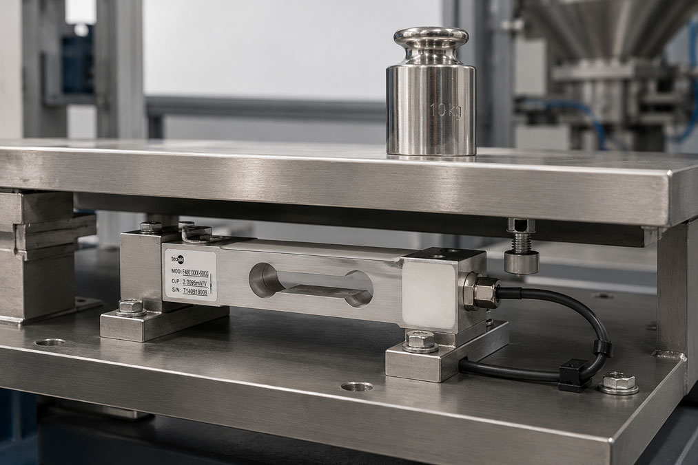
A high-quality load cell can only measure accurately if the mechanical design allows the intended force flow. In practice, many deviations are not caused by the load cell or the connected weighing electronics, but by uneven mounting surfaces, stressed frames, lateral forces, unsuitable supports or unintended force shunts.
A load cell measures the elastic deformation of its measuring body. To convert this deformation into a reproducible weight signal, the force to be measured must pass through the load cell as completely as possible and in the intended direction. If part of the load is transferred through a pipeline, stop, cable, frame contact or secondary support, the load cell detects only part of the actual load.
The opposite is also possible: lateral forces, bending moments or a mechanically stressed installation can additionally deform the measuring body. The indicated value may then be too high, too low or unstable even though the actual weight remains unchanged. Severe incorrect loading can permanently shift the zero point or mechanically damage the load cell.
Particularly with platform or single-point load cells, it is frequently assumed that the cell can simply be bolted fully between the base plate and weighing platform. In fact, only the mounting and load-introduction areas intended by the design may be supported. The spring section between them requires sufficient clearance so that it can deform elastically under load.
This article explains the force flow through a load cell, shows typical force shunts and describes how supports, platforms, pipelines, overload stops, cables and multi-cell systems should be designed.
Table of contents
- Why the mechanical installation determines the measuring accuracy
- How a strain-gauge load cell works
- What is meant by a clean force flow
- What is a force shunt?
- Why every load cell design requires a different installation concept
- Requirements for mounting surfaces and supporting structures
- Installing platform and single-point load cells correctly
- Supports, spacers and recessed surfaces
- Applying the load correctly and centrally
- Avoiding lateral forces, torsion and bending moments
- Off-centre loading and corner-load compensation
- Mechanical decoupling of the weighing structure
- Pipelines, hoses and cables as force shunts
- Vessels and platforms supported by multiple load cells
- Temperature changes and thermal expansion
- Designing stops and mechanical overload protection
- Impact loads, vibration and dynamic forces
- Determining dead load, payload and measuring range
- Routing the measuring cable without tension and with interference protection
- Recommended installation procedure
- Commissioning and mechanical functional testing
- Corner-load and repeatability testing
- Why the scale must be calibrated after installation
- Typical installation errors and their effects
- Practical example: Platform scale displays different values depending on load position
- Which information is required for the design
- Which measuring instruments / products are suitable?
- Conclusion
- Frequently asked questions about installing load cells
Why the mechanical installation determines the measuring accuracy
The technical accuracy specifications of a load cell are determined under defined test conditions. The force is applied in the intended direction and through the surfaces provided by the design. Lateral forces, friction, pipeline forces and deformation of the surrounding structure are largely excluded.
In an actual machine or scale, however, the load cell is part of a complete mechanical system. The base frame, platform, vessel, mounting screws, pipes, protective covers and stops influence the force flow.
Even a slightly distorted base plate can preload the load cell when the screws are tightened. A platform subjected to lateral stress can create an additional bending moment. A connected hose can transmit a tensile or compressive force with every movement.
The weighing electronics cannot fundamentally correct such mechanical errors. Zeroing may remove a constant initial value, but it does not eliminate load-dependent deviations, hysteresis, poor repeatability or different indications when the load position changes.
The mechanical design should therefore be treated as part of the measuring chain from the planning stage onwards. A precise load cell installed in an unsuitable structure does not result in a precise scale.
How a strain-gauge load cell works
A typical load cell has a metallic measuring body that deforms slightly and elastically under load. Strain gauges are applied to defined areas of this measuring body.
When the strain gauges are stretched or compressed, their electrical resistance changes. Several strain gauges are usually connected to form a Wheatstone measuring bridge. The bridge circuit converts the mechanical deformation into a small electrical output signal.
For many load cells, the output signal is specified in millivolts per volt. A rated output of 2 mV/V, for example, means that the load cell produces approximately 20 mV at rated load and an excitation voltage of 10 V.
The measuring body may only deform within its intended elastic range. After unloading, it must return as precisely as possible to its original condition. If it is overloaded, twisted or bent laterally, permanent deformation may occur.
Such damage is often indicated by a shifted zero point, reduced signal span, poor repeatability or a significant difference between loading and unloading.
What is meant by a clean force flow
The force flow describes the mechanical path taken by the weight force from the item being weighed through the weighing structure to the foundation.
In a simple platform scale, this path ideally runs from the item being weighed into the platform, from there into the intended load-introduction area of the load cell and then through its mounting area into the base structure.
The entire force to be measured must pass through the elastic measuring body. Only then does the deformation of the load cell correspond to the actual load.
It is not sufficient that the load cell is loaded at all. The force flow must also be reproducible. The same mass must follow the same mechanical path every time it is placed on the scale.
Rubbing guides, stiff joints, laterally contacting panels or mechanically stressed vessel connections can alter the force flow depending on the direction of movement, temperature and load position. This causes hysteresis and poor repeatability.
What is a force shunt?
A force shunt occurs when part of the force to be measured bypasses the load cell. The load is then transferred partially through another component directly into the base structure.
A simple example is a platform that contacts a lateral protective panel under load. As soon as contact occurs, the protective panel carries part of the weight force. The load cell indicates less than the actual load placed on the platform.
A hose between a weighed vessel and a stationary installation can also form a force shunt. If the hose is too stiff or preloaded, it transmits additional forces to the vessel. These forces can increase or decrease the measured result.
Typical force shunts are caused by:
- contact between the weighing platform and machine frame
- full-surface support of a platform load cell outside its intended mounting areas
- overload stops or transport locks adjusted too closely
- rigid pipelines connected to weighed vessels
- stiff cable bundles, cable ducts or energy chains
- protective covers resting on the movable weighing structure
- product bridges, contamination or compacted material
- friction in guides, joints or bearings
- additional supports or installation aids that were accidentally not removed
A force shunt does not have to be rigid and permanently present. Contacts that only occur above a certain load, during a temperature change or while the system is moving are particularly problematic. Such errors are often only temporarily visible and are therefore difficult to identify.
Why every load cell design requires a different installation concept
The term load cell covers various mechanical designs. They differ in their intended loading direction, mounting arrangement and method of load introduction.
Platform or single-point load cells are typically secured to a base plate at one end and to a platform at the other. They are designed for defined platform sizes and a specific direction of the weight force.
Bending-beam and shear-beam load cells also have a fixed mounting area and a separate load-introduction area. The elastic measuring section between the two zones must remain free to deform.
Compression force transducers are loaded through suitable compression surfaces. Depending on the design, centrally applied force through a spherical surface, load button or special mounting accessory may be required.
Tension and compression force transducers are frequently integrated into a force path by means of threads, rod ends or clevises. Lateral stress and torsion must be avoided particularly carefully in these cases.
Load pins, ring force transducers and special force transducers have their own installation requirements. There is therefore no single mounting drawing that applies to all load cells.
The data sheet, dimensional drawing and operating instructions for the specific model are always decisive. Statements such as “load cells are always bolted over their full surface” or “the force must always act exactly through the geometric centre” are not generally valid without reference to the particular design.
Requirements for mounting surfaces and supporting structures
The mounting surfaces must be sufficiently flat, clean and rigid. Unevenness can deform and mechanically preload the load cell when the mounting screws are tightened, causing a mechanical zero-point shift.
Loose particles, welding spatter, paint runs, burrs or washers placed in unsuitable positions result in point loading. The screw force is then not transferred evenly through the intended mounting area.
The base structure must remain sufficiently dimensionally stable under load. If the base plate bends, the alignment of the load cell changes and additional moments or lateral forces may occur.
The weighing platform also requires sufficient rigidity. A platform that bends significantly cannot transfer the load into the load cell in the manner intended by the corner-load compensation.
The mounting holes must be positioned accurately in relation to each other. Screws must not be used to force an incorrectly positioned hole pattern into alignment. The lateral forces created while tightening can already preload the load cell.
Before installation, it should be checked whether:
- the supporting surfaces are flat and free from damage
- the hole spacing corresponds to the manufacturer’s drawing
- the structure remains sufficiently rigid under rated load
- there is sufficient clearance for the load cell to deform
- the screw length and thread engagement are suitable
- no screw bottoms out in a threaded hole
Installing platform and single-point load cells correctly
A single-point load cell is mounted so that one end is rigidly connected to the base structure. The other end supports the weighing platform. The measuring spring between the two ends deforms under load.
Only the mounting areas provided by the design may contact the base plate and platform. If the load cell rests on a surface along its full length, the spring section cannot deform freely.
This creates an internal force shunt within the installation. The load cell responds insufficiently, non-linearly or depending on the load position. In the worst case, it may already be mechanically overloaded while being bolted into place.
If the load cell does not have clearly visible raised support surfaces, this does not automatically mean that it may be mounted over its full surface. Depending on the model, spacers, mounting blocks or structurally recessed surfaces may be required.
The exact location and size of these supports are specified in the dimensional drawing or operating instructions. The spaces between them must not be bridged by either the base plate or the platform.
The weighing platform should be aligned with the load cell in accordance with the manufacturer’s drawing. With many single-point versions, the centre of the platform is aligned with the intended centre of the load cell.
The maximum permissible platform size must be observed. A larger platform creates greater lever arms and therefore higher bending and torsional moments during off-centre loading.
Supports, spacers and recessed surfaces
Supports transfer forces between the load cell, platform and base structure. Their shape must suit the load cell and must not restrict elastic deformation.
With a platform load cell, there is usually one support in the mounting area and another in the load-introduction area. The central measuring section remains unsupported.
Spacers may be required so that the load cell can deform downwards or upwards under load without contacting the base plate or platform.
The spacers must:
- be sufficiently rigid
- be manufactured with parallel surfaces
- fully support the intended mounting areas
- allow a reproducible bolted connection
- provide sufficient clearance for the complete deflection
Individual washers are not automatically suitable as spacers. They can create point stresses and load the supporting surface unevenly.
The required support height must not be selected solely by visual judgement. Manufacturing tolerances, platform deflection and a possible overload travel must be taken into account in addition to the normal deflection.
If the manufacturer’s drawing requires a recessed mounting surface, this should be machined into the structure or created using an appropriate mounting block. An improvised installation can significantly reduce the specified measuring accuracy.
Applying the load correctly and centrally
The weight force must be applied in the direction specified by the manufacturer. This direction is frequently indicated by an arrow on the load cell or in the dimensional drawing.
For a compression load cell, central force application means that the resultant force passes through the intended loading point. An inclined or laterally offset loading surface additionally creates a bending moment.
Depending on the design, spherical load surfaces, pendulum supports, load buttons, rod ends or special mounting kits are used. These components enable defined load application and can compensate for small alignment deviations.
However, an alignment element must not be regarded as a substitute for a fundamentally inclined or unstable design. Joints and pendulum supports also have limited angular and lateral-force ranges.
With tension force transducers, the force axis must pass through both connection points. Rod ends that are twisted relative to each other or misaligned threads create lateral forces and torsion.
The load introduction should be considered as a force vector during the CAD design stage. Not only the static rated load, but also the actual movement of the machine must be taken into account.
Avoiding lateral forces, torsion and bending moments
A load cell is generally designed for one primary measuring direction. Forces acting perpendicular to this direction are referred to as lateral or side forces.
Lateral forces can be caused by inclined supporting surfaces, friction, acceleration, lateral guides or connected pipes and cables. They produce additional deformation that does not correspond to the actual weight.
Torsion occurs when the load cell is twisted around its longitudinal or measuring axis. A typical example is a platform twisted by incorrectly aligned screws or a one-sided stop.
Bending moments occur when the force does not act along the intended line of action. The distance between the force line and measuring axis acts as a lever arm.
A platform load cell described as “off-centre-load compensated” is not protected against unlimited lateral forces. The compensation applies to defined off-centre vertical loads within the approved platform dimensions. It does not permit arbitrary horizontal forces or torsional moments.
In machines with acceleration, it must be considered that the mass also produces horizontal inertial forces. A scale that operates correctly at standstill may be subjected to significantly different loads during rapid movement.
Off-centre loading and corner-load compensation
Single-point load cells are designed and adjusted so that a load placed at different positions within a defined platform produces approximately the same weight indication.
This corner-load compensation is a major advantage of this design. It enables a platform scale to be built with only one centrally arranged load cell.
However, the compensation only applies within the specified mechanical limits. These include in particular:
- maximum platform dimensions
- sufficient platform rigidity
- correct alignment with the load cell
- the intended direction of loading
- proper mounting surfaces
If the platform is larger than specified, the moments acting during corner loading increase. The indicated value may then vary depending on the position of the load.
A very thin platform may bend locally. The load is then not transferred as a rigid resultant force, but changes the mechanical loading of the load cell.
A corner-load test is therefore required after the complete scale has been assembled. Compensation within the individual load cell alone does not confirm the accuracy of the complete system.
Mechanical decoupling of the weighing structure
The weighed structure must be movable relative to the stationary machine frame so that the full weight force is transferred through the load cell or load cells.
At the same time, it must be protected against tipping, shifting or impermissible movement. These two requirements can conflict with each other.
Guides, stops and lift-off protection devices must therefore be designed with defined clearance or with suitable load-cell mounting kits. They must not carry any relevant proportion of the load during normal weighing operation.
For vessels, pendulum supports or self-centring load introductions can permit thermal movement. Horizontal restraints limit movement caused by agitators, wind or pipeline forces.
Mechanical decoupling does not mean that the structure may move freely and uncontrollably. The horizontal and vertical forces that occur must be known and carried by components intended for this purpose.
The installation concept must take into account normal weighing operation as well as maintenance, transport, cleaning, seismic loads, wind loads and possible fault conditions.
Pipelines, hoses and cables as force shunts
Weighed vessels are frequently connected to the surrounding installation by pipelines, hoses, cables, pneumatic lines and grounding straps. Each of these components can transmit forces.
Depending on temperature, internal pressure and installation condition, a rigid pipeline acts like an additional spring. It can load the vessel upwards, downwards or laterally.
Pipelines that are forced into alignment under stress during installation and then bolted to the vessel are particularly critical. The stored mechanical stress changes the zero point and may shift further with temperature changes.
Suitable measures may include:
- flexible hose or expansion-joint sections
- sufficiently long and stress-free pipe bends
- symmetrical pipe routing
- mechanically decoupled pipe supports
- low stiffness in the weighing direction
- defined guidance in the directions that are not being measured
The appropriate solution depends on the medium, pressure, temperature, hygiene requirements and permissible movement. A flexible hose is not automatically force-free. It also has spring stiffness and can change its shape due to internal pressure.
Cables should be routed from the weighed structure to the stationary structure with a loose, reproducible loop. A tightly stretched cable or rigid cable duct can cause a relevant error even with small measuring ranges.
Product deposits can also create a force shunt. A bulk-material vessel connected to an adjacent component by a material bridge can no longer be weighed reliably.
Vessels and platforms supported by multiple load cells
Large platforms and vessels are frequently supported by three or four load cells. The load is then distributed across several measuring points.
Three supports geometrically define a plane and can provide an unambiguous load distribution with a rigid structure. Four or more supports are more sensitive to height differences and deformation.
If one of four load cells is slightly higher than the others, it may carry a disproportionately large share of the load. Another cell is correspondingly unloaded.
The sum of the signals may initially appear plausible with a constant total load. Individual cells may nevertheless already be overloaded or provide strongly varying signals as the load distribution changes.
The following are therefore important in multi-cell systems:
- equal support heights
- rigid vessel or platform construction
- correct alignment of all load cells
- uniform load distribution
- suitable mounting kits
- compensation for thermal expansion
- checking the individual signals
The rated load of each load cell must not simply be calculated by dividing the total weight by the number of cells. Unequal distribution, the centre of gravity, dynamic loads and safety reserves must be considered.
With a vessel supported by four load cells, one corner can carry significantly more than one quarter of the total weight. The design must therefore take the most unfavourable realistic load case into account.
Temperature changes and thermal expansion
Temperature affects both the load cell and the surrounding structure. The load cell has specified temperature coefficients and a permissible operating range.
Platforms, vessels, frames and pipelines also expand when heated. If this movement is mechanically restricted, horizontal forces and stresses occur.
With large vessels, even a moderate temperature change can produce a measurable change in length. Rigid supports or guides transfer the resulting forces to the load cells.
Mounting kits for vessel weighing systems are often designed to permit changes in length while still guiding the vessel sufficiently. The exact arrangement depends on the number of supports and the expected direction of movement.
One-sided heating can also create temperature gradients. If only one load cell is heated by a hot pipeline or solar radiation, the individual signals may change differently.
Load cells should therefore be exposed to conditions that are as similar as possible. Direct radiant heat, hot cleaning media or local cold zones must be considered in the design.
Designing stops and mechanical overload protection
A mechanical stop can protect the load cell against overload. It limits movement of the platform or load-introduction component before the measuring body is deformed excessively.
The stop must not make contact within the normal measuring range. Otherwise, it forms a force shunt and distorts the indication.
The required gap must be selected so that:
- the full deflection up to the intended rated load remains possible
- manufacturing tolerances and platform deflection are taken into account
- the stop becomes effective before a damaging overload occurs
- temperature changes do not alter the gap impermissibly
A general gap value is not suitable for every load cell. The basis is the deflection, permissible limit load and installation geometry of the specific model.
The stop itself must be sufficiently rigid. A soft stop may take over the load too late and still allow the load cell to be overloaded.
With impact loading, a static stop alone may be insufficient. Falling loads briefly generate forces considerably greater than their weight. Damping elements or a larger measuring range may be required.
Transport locks must be released completely or placed in the intended operating position before commissioning. A transport lock that has only been partially released is a typical force shunt.
Impact loads, vibration and dynamic forces
The rated load of a load cell does not automatically apply to every dynamic load. If a mass is dropped onto the platform, the peak force can be several times greater than the static weight force.
Agitators, conveyors, dosing screws and vibrating machines also produce alternating forces. The load cell then detects not only the weight, but also dynamic accelerations.
The mechanical design must prevent resonances from occurring or the measuring body from being subjected continuously to high lateral forces.
For dynamic applications, the following must be assessed, among other factors:
- maximum acceleration
- impact energy
- vibration frequency
- rigidity of the platform and base frame
- sampling rate and filtering of the weighing electronics
- permissible limit load and breaking load of the load cell
Strong electronic damping can stabilise a fluctuating indication, but it does not eliminate mechanical incorrect loading. It also increases the settling time and may conceal rapid weight changes.
Determining dead load, payload and measuring range
The measuring range must accommodate the dead load of the complete weighing structure and the maximum payload.
For a platform scale, the platform, attachments, vessel, brackets and permanently installed components form part of the preload. Only the remaining capacity is available as the usable weighing range.
A load cell with a rated load of 100 kg does not automatically provide a 100 kg payload when the platform itself weighs 40 kg. Without additional reserves, only 60 kg remain mathematically.
The following must also be considered:
- unequal load distribution
- dynamic peak forces
- possible incorrect loads
- installation and maintenance loads
- the required overload reserve
An excessively large measuring range, on the other hand, reduces the usable signal change per kilogram. This can reduce the resolution and accuracy of the complete system.
The selection is therefore a compromise between sufficient mechanical reserve and the best possible utilisation of the rated load.
Routing the measuring cable without tension and with interference protection
The connection cable must not transmit any relevant mechanical force to the load cell. It requires suitable strain relief and sufficient freedom of movement.
The strain relief must not be attached to the measuring body in a manner that restricts its deformation. The cable outlet intended by the manufacturer must remain free.
The measuring signal from a strain-gauge load cell is very small. The cable should therefore be routed separately from motor, variable-frequency-drive, contactor and power cables.
Only suitable shielded, low-capacitance measuring cables should be used for extensions. Transitions and terminal points must be protected against corrosion and remain electrically stable.
The cable shield and equipotential bonding must be connected in accordance with the manufacturer’s instructions and the installation concept. Multiple grounding points can cause equalising currents and interference.
Welding currents must not flow through the load cell or its measuring cable. If welding work has to be carried out on the installation, the load cell and electronics must be protected and suitable current paths or equipotential bonding connections must be provided.
Recommended installation procedure
Before installation, the model, rated load, loading direction and connection data are compared with the design. The load cell is inspected for visible transport or installation damage.
The base plate, platform, mounting blocks and holes are then checked. Burrs, welding spatter, chips and contamination must be removed.
The load cell is placed in the installation position without force. The screws are initially only tightened lightly so that the components can align themselves.
It is then checked whether:
- the mounting areas are fully and evenly supported
- the spring section remains free
- the platform and base structure do not make unintended contact
- the cable is routed without mechanical tension
- the intended loading direction is observed
The mounting screws are tightened evenly and with the torque specified by the manufacturer. Insufficient torque can cause movement and hysteresis. Excessive torque can damage threads, the measuring body or mounting surfaces.
The output signal should be observed during installation. A strong change when a single screw is tightened indicates mechanical stress, uneven surfaces or an unsuitable mounting arrangement.
After mechanical installation, the cable, electronics and shielding are connected. Only then is the platform loaded gradually and in a controlled manner.
Commissioning and mechanical functional testing
Before calibration, it is first checked whether the zero signal is stable. After a short settling period, the indication must not continue to drift.
A slowly drifting zero point can be caused by temperature equalisation, mechanically stressed pipelines, cable forces or a damaged load cell.
The platform or vessel is then moved carefully by hand in the permissible directions. Contacts, friction points and stops adjusted too closely can often be identified in this way.
A small test load is applied and removed several times. After unloading, the indication should return reproducibly to the original value.
The load is then increased step by step. At every step, the signal, mechanical freedom of movement and possible contacts are checked.
With a multi-cell scale, the individual signals from the load cells should also be examined. An unusually high or low load on one cell may indicate a height difference, mechanical stress or uneven load distribution.
Corner-load and repeatability testing
With a platform scale, a suitable test load is placed successively in the centre and at several positions near the corners.
The indication should remain within the tolerance specified for the complete scale. Larger deviations may be caused by:
- a platform that is too large or insufficiently rigid
- incorrect alignment of the load cell
- uneven mounting surfaces
- lateral contact of the platform
- mechanically stressed mounting screws
- a damaged load cell
For the repeatability test, the same load is applied repeatedly at the same position. The platform should be completely unloaded between measurements.
Different indications with the same load and position frequently indicate friction, loose connections, changing force shunts or a mechanically damaged load cell.
The scale should also be loaded in ascending and descending steps. A significant difference between loading and unloading can indicate mechanical hysteresis.
Why the scale must be calibrated after installation
Calibration of an individual load cell does not replace calibration of the complete scale. The mounting structure, platform, supports and weighing electronics influence the overall result.
After installation, the zero point and span are checked using suitable reference weights or a traceable force reference.
A single-point adjustment at the upper end of the measuring range may be sufficient for simple applications, but it does not reveal non-linearity or errors in the lower range. Several load points should be used for higher requirements.
Calibration should be performed with both increasing and decreasing loads. This makes hysteresis and return to zero visible.
After changes to supports, platform, pipelines, overload stops or mounting screws, the scale must be checked again. A purely mechanical modification can alter the characteristic of the complete system.
Typical installation errors and their effects
| Installation error | Possible effect | Better approach |
|---|---|---|
| Load cell clamped over its full surface between two plates | Spring deformation blocked, signal too small or non-linear | Support only the intended mounting areas and keep the spring section free |
| Uneven or contaminated mounting surface | Mechanical preload and shifted zero point | Machine the surfaces flat and clean them before installation |
| Mounting holes are not aligned | Lateral forces already occur while tightening the screws | Manufacture the hole pattern accurately and do not use screws as alignment tools |
| Platform larger than approved | Excessive moments and corner-load deviations | Observe the maximum platform dimensions for the model |
| Platform contacts the protective frame | Load-dependent force shunt | Provide sufficient clearance throughout the complete weighing range |
| Overload stop adjusted too closely | Indication is limited before the rated load is reached | Adjust the gap using the model-specific deflection |
| Rigid pipeline connected to the weighed vessel | Zero-point drift, hysteresis and temperature-dependent deviation | Mechanically decouple the pipeline and install it without stress |
| Cable routed tightly between the load cell and frame | Additional tensile force and unstable indication at small loads | Use a loose cable loop and suitable strain relief |
| Lateral or inclined load on a compression load cell | Measurement deviation and possible permanent deformation | Use a suitable load-introduction component or mounting accessory |
| Four load cells mounted at different heights | Uneven load distribution and overloading of individual cells | Align the supports and check the individual signals |
| Load cell installed using a hammer | Impact overload and permanent zero-point shift | Install without force while observing the output signal |
| Transport lock not fully released | Partial force shunt and limited measuring travel | Check the operating position before calibration |
| Welding current passed through the load cell | Damage to strain gauges, cable or weighing electronics | Provide suitable equipotential bonding and a safe welding-current path |
Practical example: Platform scale displays different values depending on load position
A compact dosing scale is built using a single-point load cell. The load cell does not have clearly raised supporting surfaces. It is therefore bolted directly to a solid base plate along its entire length.
The upper platform is also attached to the complete upper surface of the load cell without a spacer. After electrical adjustment, the scale initially displays a plausible value when a test load is placed in the centre.
If the same load is placed in a corner, the indication deviates significantly. At higher loads, the signal also no longer increases proportionally.
The load cell is initially replaced with a new unit. The behaviour remains almost unchanged. This indicates that the cause is not the individual load cell, but the installation situation.
Mechanical inspection shows that the spring section of the load cell is already almost in contact with the base plate and platform when unloaded. Additional contacts occur under load. A large part of the weight force is transferred directly between the platform and base plate, bypassing the elastic measuring section.
The design is then modified in accordance with the mounting drawing. Parallel mounting blocks are provided in the fixed mounting area and load-introduction area. The central section is given sufficient clearance for the full deflection.
The platform is aligned with the load cell and the mounting screws are tightened to the specified torque. The zero signal is observed during tightening.
After recalibration, the scale provides values that agree considerably better during central and off-centre loading. Linearity across the measuring range also improves.
The example shows that a load cell without visible steps or raised sections must not automatically be mounted over its full surface. The mounting zones defined in the manufacturer’s drawing and the required clearance for the measuring spring are decisive.
Which information is required for the design
The maximum mass alone is not sufficient for selecting a suitable load cell.
At least the following information is required:
- dead load of the weighing structure
- minimum and maximum payload
- required resolution and accuracy
- platform size or vessel geometry
- number and position of the load cells
- static or dynamic loading
- possible lateral forces and moments
- temperature and environmental conditions
- degree of protection and cleaning requirements
- existing pipelines, hoses and cables
- required output signal
- existing weighing electronics or PLC
- overload, explosion-protection or safety requirements
- calibration or legal-for-trade requirements
Drawings of the planned installation are also helpful. Particularly with special designs, the suitability of a load cell can only be assessed when the force flow, supports and possible secondary forces are visible.
Which measuring instruments / products are suitable?
The displacement, force, speed, torque and vibration sensors category contains different sensor principles for mechanical engineering, automation, test benches and industrial weighing technology.
In addition to load cells, the range includes tension and compression force transducers, bending and shear beams, load pins, ring force transducers and other special designs. The suitable model depends on the type of force, installation space, measuring range, mechanical loading and required output signal.
The WIKA platform load cells category contains single-point load cells for compact bench, platform, dosing and checkweighing scales.
The WIKA F4801 platform load cell is available in different rated loads and is suitable for compact scales using a single load cell. The specified platform size, mounting arrangement and loading direction must be taken into account in the design.
For larger rated loads, the WIKA F4818 platform load cell is available, among other models. Here too, the permissible platform size is not a freely variable value, but part of the mechanical design.
The WIKA F4885 platform load cell is available for various compact weighing applications and, depending on the version, has a multi-core connection for precise signal acquisition.
For larger vessels, silos, machines or force-measuring applications, other load-cell or force-transducer designs may be more suitable. These include shear beams, compression force transducers, tension/compression force transducers and load pins.
The load cell frequently provides a small strain-gauge bridge signal in mV/V. Suitable weighing electronics, a measuring amplifier or a PLC weighing module are required for further processing. Depending on the system, analogue signals, digital measured values, limit values or dosing functions can be provided.
ICS Schneider Messtechnik assists with selecting the load cell, assessing the installation situation and matching it to the weighing electronics. For a reliable recommendation, a technical drawing, the dead load, payload, platform or vessel dimensions and information about possible secondary forces should be provided.
Conclusion: A load cell only measures the force that actually flows through it
The accuracy of a scale depends significantly on the mechanical design. The load cell must be mounted on flat and sufficiently rigid surfaces and may only be loaded in the intended direction.
With platform and single-point load cells, only the intended mounting areas may be supported. The spring section must have sufficient clearance. Full-surface clamping can block deformation and create an internal force shunt.
Pipelines, cables, stops, protective panels and deposits must not divert any part of the load around the load cell. At the same time, lateral forces, torsion and bending moments must be avoided as far as possible.
Corner-load compensation does not mean that the platform size and mechanical loading can be selected arbitrarily. The dimensions and installation conditions approved by the manufacturer remain binding.
Overload stops must provide sufficient clearance for the normal deflection. Stops adjusted too closely distort the measurement, while stops adjusted too far may not protect the load cell adequately.
After installation, the complete scale must be tested and calibrated using suitable reference loads. Calibration of the individual load cell cannot account for the mechanical influences of the subsequent installation.
Taking the force flow, supports, decoupling and secondary forces into account during the design stage improves not only the measuring accuracy, but also the service life and operational reliability of the complete weighing system.
Frequently asked questions about installing load cells
What is a force shunt in a load cell installation?
A force shunt occurs when part of the force to be measured is transferred into the base structure through another component instead of through the load cell. The load cell then does not detect the full load.
Which components frequently cause force shunts?
Typical causes include rigid pipelines, tensioned cables, protective covers, overload stops adjusted too closely, transport locks, lateral frame contacts and product deposits.
May a platform load cell be supported over its full surface?
As a general rule, only the mounting and load-introduction areas specified by the manufacturer may be supported. The elastic spring section must remain free to deform. The drawing for the specific model is decisive.
What happens with full-surface mounting?
The deformation of the measuring spring may be restricted. This can result in an insufficient signal, non-linearity, poor corner-load performance or a load-dependent force shunt.
Do I have to design recessed supporting surfaces myself?
If the manufacturer’s drawing specifies separate mounting areas and clearances, these must be implemented in the design. This can be achieved using machined surfaces, mounting blocks or suitable spacers.
Can I use ordinary washers as spacers?
This is not generally recommended. Individual washers can cause point stresses and uneven support. Spacers should have parallel surfaces, sufficient rigidity and dimensions that match the intended mounting areas.
How much clearance is required beneath a platform load cell?
The clearance must allow the full deflection, including tolerances and possible platform bending. The required value is specified by the manufacturer for the particular model.
Why must the mounting surface be flat?
An uneven surface mechanically stresses the load cell when the screws are tightened. This can shift the zero point and produce additional lateral forces or bending moments.
May the mounting surface be painted?
A thick, uneven or soft paint layer can settle and alter the bolted connection. The specific surface requirements should be checked against the manufacturer’s instructions and the mechanical design.
What torque is required for the mounting screws?
The permissible or recommended torque is model-specific. It must be obtained from the data sheet or operating instructions.
Can excessive tightening torque damage the load cell?
Yes. It can damage threads, the measuring body or mounting surfaces and can mechanically preload the load cell.
Why should the signal be observed while tightening the screws?
A strong signal change when one screw is tightened may indicate uneven surfaces, incorrectly positioned supports or mechanical stress.
What does load introduction mean?
Load introduction refers to the area and method through which the force to be measured is transferred into the measuring body of the load cell.
Must the force always act exactly in the centre?
This depends on the load cell design. Compression force transducers frequently require central load application. Single-point load cells can compensate for off-centre loads within a defined platform.
What is corner-load compensation?
It ensures that a vertical load placed within the approved platform produces approximately the same measured value regardless of its position.
May the platform be larger than specified in the data sheet?
This is not recommended without a technical assessment. A larger platform increases the lever arms and therefore the bending and torsional moments during off-centre loading.
Why must the platform be rigid?
A bending platform changes the load introduction and can cause different indications depending on the load position.
What are lateral forces?
Lateral forces act sideways or perpendicular to the intended measuring direction. They can cause measurement errors and permanently damage the measuring body.
How are lateral forces generated in a scale?
They can be caused by inclined mounting surfaces, lateral guides, rigid pipelines, acceleration, friction or misaligned load introduction.
What is torsion in a load cell?
Torsion is a twisting load on the measuring body around its axis. It can be caused, for example, by connections twisted relative to each other or a mechanically stressed platform.
Can an off-centre-load compensated load cell withstand arbitrary lateral forces?
No. The compensation only applies to defined vertical load positions and mechanical limits. Horizontal forces and high torsional moments must still be avoided.
How do pipelines affect a vessel weighing system?
Pipelines can transfer additional forces to the vessel due to their stiffness, thermal expansion, internal pressure or installation stress.
Is a flexible hose sufficient for mechanical decoupling?
Not always. A flexible hose also has spring stiffness and can transmit forces under pressure or during movement. The specific arrangement must be assessed mechanically.
How should a load-cell cable be routed?
It should be routed without tension, with a suitable loop and strain relief. Parallel routing with power cables should be avoided.
Can a cable influence the measured result?
Yes. With small measuring ranges, even a tensioned or stiff cable can apply a relevant tensile or bending force to the weighing structure.
Why must a stop not remain in permanent contact with the platform?
The stop would carry part of the weight force and therefore create a force shunt.
How is an overload stop adjusted?
The gap must allow the normal deflection and limit movement before a damaging overload occurs. Adjustment is based on the model-specific data.
What is a transport lock?
It secures the movable weighing structure during transport or installation. Before weighing operation, it must be released completely or placed in the intended operating position.
Why does a scale not return to zero after a load has been removed?
Possible causes include friction, a changing force shunt, mechanical overload, loose screws, stressed pipelines or a damaged load cell.
Why does a scale display different values at different corners?
Possible causes include a platform that is too large or insufficiently rigid, an incorrectly mounted load cell, lateral contact or an uneven base plate.
How is a corner-load test performed?
A suitable test load is placed successively in the centre and at defined positions on the platform. The indicated values are compared.
Why must the scale be calibrated after installation?
Only in the complete installation do the platform, supports, pipelines, electronics and mechanical influences act together. Calibration of the individual load cell does not account for these factors.
Can zeroing correct a mechanical installation error?
It can compensate for a constant zero-point offset. Load-dependent errors, hysteresis, poor corner-load performance and changing force shunts are not eliminated.
How is the correct measuring range selected?
The dead load, maximum payload, unequal load distribution, dynamic peak forces and a suitable overload reserve must all be considered.
Can an oversized load cell be disadvantageous?
Yes. If only a small part of the rated range is used, the usable electrical signal is correspondingly smaller. This can reduce the resolution and accuracy of the complete system.
Why can four load cells carry different loads?
Possible causes include differences in support height, an off-centre centre of gravity, a deformed frame or thermal stresses.
How can uneven load distribution be identified?
If the individual signals are accessible, the loads on the individual load cells are compared. Large differences should be investigated mechanically.
May welding be carried out on an installation containing a load cell?
Welding currents must not flow through the load cell, measuring bridge or connection cable. Suitable protection and equipotential bonding measures are required before welding work.
Which information is required for an enquiry?
The dead load, payload, platform or vessel size, number of supports, required accuracy, dynamic loading, possible lateral forces, environmental conditions, output signal and preferably a technical drawing of the installation are required.