


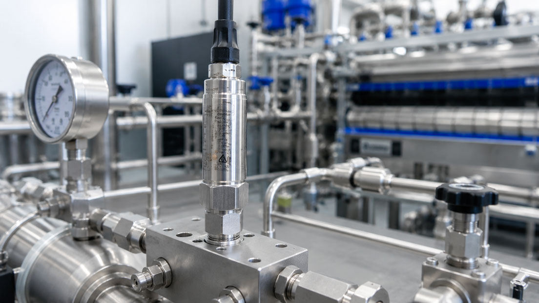
Hydrogen is used in electrolysis plants, compressors, storage systems, fuel-cell systems, test benches, pipeline networks and refuelling stations at widely varying pressures. Depending on the application, the measuring range extends from a few millibars to several hundred or even 1,000 bar.
However, a pressure sensor for hydrogen must not be selected solely on the basis of its pressure range. Hydrogen has a very small molecular size, can diffuse through certain materials and seals and, under unfavourable conditions, can affect the mechanical properties of metallic components. These requirements become even more demanding at high pressures, with rapid load changes and a large number of pressure cycles.
The complete wetted construction is therefore decisive. This includes the measuring diaphragm, pressure connection, welds, filling fluids, seals and any coatings. The general statement “stainless steel” is not sufficient because different stainless-steel grades, heat treatments and component geometries can behave differently when exposed to hydrogen.
Approvals must also be interpreted correctly. An ATEX approval confirms that a specific instrument version is suitable for a defined potentially explosive atmosphere. However, it is not a general confirmation that all wetted components are suitable for hydrogen at the actual pressure, temperature and expected number of pressure cycles.
Conversely, not every hydrogen pressure measuring point automatically requires an ATEX sensor. The decisive factors are the hazardous-area classification, the possible formation of an explosive atmosphere, the protection concept of the installation and the operator’s requirements.
This article explains how to select a hydrogen pressure sensor from a technical perspective, the importance of diaphragm materials, seals, pressure connections and leakage rates, and how ATEX, UN R134, former EC79 approvals, SIL and electrical output signals must be distinguished from one another.
Table of contents
- Why hydrogen places special requirements on pressure sensors
- Which application data is required before selection
- Distinguishing between gaseous and liquid hydrogen
- Correctly assessing hydrogen embrittlement
- Diffusion, permeation and long-term stability
- Measuring diaphragm and measuring-cell construction
- Fully evaluating wetted materials
- Elastomer seals, metal seals and welded designs
- Selecting a pressure connection for hydrogen and high pressure
- Defining the leakage rate and leak test
- Correctly distinguishing measuring range, operating pressure and overload
- Pressure measurement at 350, 700 and 1,000 bar
- Pressure cycles, pulsations and fatigue
- Gauge pressure, absolute pressure or sealed gauge?
- Assessing accuracy and total error
- Response time and dynamic pressure measurement
- Medium, ambient and process temperature
- 4–20 mA, 0–10 V and ratiometric output signals
- ATEX and IECEx in hydrogen applications
- Correctly assessing EC79 and UN R134
- SIL and functional safety
- Gas purity, cleanliness and contamination
- Installing the pressure sensor correctly
- Including pipelines, valves and adapters in the assessment
- Calibration and periodic testing
- Typical hydrogen applications
- Direct comparison of selection criteria
- Typical selection errors
- Practical example: Pressure sensor for a 1,000-bar hydrogen test bench
- Which information is required for a technical enquiry
- Which measuring instruments / products are suitable?
- Conclusion
- Frequently asked questions about hydrogen pressure sensors
Why hydrogen places special requirements on pressure sensors
A general industrial pressure sensor may be suitable for air, water, hydraulic oil or many technical gases without automatically being approved for hydrogen. The reason is not only the flammability of the medium, but also its behaviour in relation to metallic and non-metallic materials.
Hydrogen can enter materials and move within their microstructure. Depending on the material, pressure, temperature, mechanical stress and duration of exposure, this can change strength, ductility and fatigue behaviour.
Hydrogen can also permeate elastomers, plastics and certain metallic diaphragms. In a pressure sensor, this may result in gradual leakage, bubble formation, zero-point shifts or an influence on the internal measuring cell.
The small molecular size also makes every interface relevant. Threads, seals, welds, electrical feedthroughs and adapters must be considered as part of the complete pressure boundary.
At high pressures, it is not only the mechanical load that increases. The stored energy of the compressed gas also rises considerably. A leak or component failure can therefore have significantly more serious consequences than in a low-pressure application.
Selecting a hydrogen pressure sensor is therefore a combined assessment involving materials engineering, pressure engineering, explosion protection, electrical measurement technology and system integration.
Which application data is required before selection
The statement “hydrogen, 700 bar” is not sufficient for reliable product selection. The question of whether the application involves a static storage system, a cyclically operated test bench or a refuelling station can already result in different sensor designs.
Before selection, at least the following conditions should be clarified:
- gaseous or liquid hydrogen
- purity and possible accompanying substances
- minimum, normal and maximum operating pressure
- possible pressure peaks and rate of pressure change
- number and frequency of pressure cycles
- medium and ambient temperature
- gauge, absolute or differential pressure measurement
- required accuracy and long-term stability
- pressure connection and existing piping technology
- permissible leakage rate
- electrical output signal
- supply voltage and connected evaluation electronics
- hazardous area and required instrument marking
- mobile or stationary application
- required automotive, marine, SIL or other approvals
It must also be clarified whether the sensor is used only for process monitoring or forms part of a safety-related shutdown function. A sensor used purely for indication may be subject to different requirements from an instrument whose failure could result in a dangerous plant condition.
Distinguishing between gaseous and liquid hydrogen
Most industrial hydrogen pressure sensors are intended for gaseous hydrogen. Depending on the application, pressures can range from a few millibars to several hundred bar.
Liquid hydrogen additionally creates extreme temperature requirements. Its boiling point is approximately −253 °C. A conventional pressure sensor must not be exposed directly to this temperature solely because it has a general hydrogen approval.
In cryogenic applications, the sensor is frequently separated from the cryogenic medium by a suitable impulse line, thermal stand-off or specially designed measuring arrangement. It must be ensured that no impermissible heating, evaporation, condensation or pressure distortion occurs.
Even with gaseous hydrogen, significant temperature changes can occur due to expansion, compression and rapid filling processes. The maximum process temperature is therefore not always identical to the normal ambient temperature.
An approval for gaseous hydrogen at room temperature must not be transferred to liquid hydrogen or strongly cryogenic gas conditions without confirmation from the manufacturer.
Correctly assessing hydrogen embrittlement
The term hydrogen embrittlement covers various mechanisms through which hydrogen can adversely affect the mechanical properties of a material.
The risk does not depend solely on the material designation. Relevant factors include:
- alloy composition
- microstructure and heat treatment
- hardness and strength level
- welding process and weld quality
- residual mechanical stresses
- hydrogen pressure and temperature
- static or cyclic loading
- component geometry and notches
The general statement “stainless steel is resistant to hydrogen” is therefore insufficient. Although austenitic stainless steels are frequently used in hydrogen applications, the specific material grade, manufacturing process and operating conditions must still be considered.
High-strength steels in particular can be more susceptible to hydrogen-related cracking. Small threaded areas, sharp transitions and highly stressed diaphragms must be designed accordingly.
For a pressure sensor, the manufacturer’s approval of the complete wetted construction is more meaningful than a general material compatibility table. Nevertheless, the operator should confirm that the specified materials are suitable for the medium and process.
Diffusion, permeation and long-term stability
Hydrogen can diffuse through certain materials. With a thin metallic separating diaphragm, part of the gas can pass through the diaphragm and enter the space behind it.
In oil-filled pressure measuring cells, permeating hydrogen can enter the transmission fluid. Under changing pressure or temperature conditions, gas bubbles can form there. These affect pressure transmission and can cause zero-point shifts, hysteresis or delayed response.
A dry, welded measuring cell can reduce this risk, provided that all wetted materials and welded connections are designed for the application.
Special barrier coatings or diaphragm constructions are also used for particularly demanding measuring points. Such solutions can reduce permeation, but must be qualified for the specific sensor and measuring range.
Permeation is often not an immediately visible fault. A sensor may operate correctly during commissioning and only begin to drift after prolonged hydrogen exposure. Long-term stability, pressure cycles and the intended maintenance period are therefore important selection criteria.
Measuring diaphragm and measuring-cell construction
The measuring diaphragm is one of the most highly stressed components of the pressure sensor. It is in direct contact with the hydrogen and deforms with every pressure change.
Depending on the sensor technology, deformation is detected using thin-film strain gauges, piezoresistive silicon elements or resonant structures, for example.
In a media-isolated silicon measuring cell, a metallic diaphragm transfers the pressure to the actual sensing element. This construction protects the electronics from the medium, but may contain a transmission fluid.
In a dry thin-film measuring cell, the sensing elements are applied directly to a metallic measuring body. This can allow a completely welded design without filling fluid.
No technology is fundamentally superior for every application. The following must be assessed:
- hydrogen approval of the wetted materials
- diaphragm thickness and mechanical loading
- presence of a filling fluid
- permeation protection
- pressure-cycle resistance
- overload and burst pressure
- accuracy and long-term stability
- temperature behaviour
A flush diaphragm is not automatically more suitable for hydrogen than an internal pressure channel. It may have a larger surface area and a very thin separating diaphragm. Suitability must therefore be confirmed for the specific model.
Fully evaluating wetted materials
The wetted area includes more than just the diaphragm and visible process connection. Depending on the construction, internal pressure channels, welds, seals, filling fluids and adapters may also come into contact with the hydrogen.
A complete material list should therefore identify all wetted components wherever possible. Statements such as “stainless-steel housing” provide no information about whether the measuring diaphragm, internal pressure channel or process seal is made from the same material.
With a welded sensor, the filler metals and heat-affected zones are also part of the pressure boundary. A suitable base material can be adversely affected by an unsuitable joining process.
Other constituents of the medium must also be considered during assessment. Moisture, oxygen, electrolyte residues, lubricants or cleaning media can change the corrosion and ageing conditions.
The material selection should always be based on the maximum concentration, temperature, pressure load and exposure duration. ICS Schneider Messtechnik can recommend suitable sensor versions, but the final confirmation of media compatibility must be provided on an application-specific basis by the operator and manufacturer.
Elastomer seals, metal seals and welded designs
Elastomer seals enable compact, detachable pressure connections. With hydrogen, however, permeation, swelling, extrusion and rapid depressurisation can be problematic.
Whether FKM, EPDM, FFKM, NBR or another sealing material is suitable cannot be determined from the material group alone. The specific compound, temperature, pressure differential, sealing groove and depressurisation rate play a major role.
During rapid depressurisation, hydrogen that has previously penetrated the elastomer can expand. This can cause internal bubbles, cracks or surface delamination. The effect is frequently referred to as explosive decompression or rapid gas decompression.
Metal seals and coned-and-threaded high-pressure connections can avoid permeation through elastomers. However, they require highly accurate sealing surfaces, defined tightening torques and a suitable mating connection.
A fully welded measuring cell reduces the number of possible sealing points inside the sensor. The external process connection may nevertheless require a separate seal or metallic sealing geometry.
For high pressures and low permissible leakage rates, a design with as few interfaces as possible is therefore often advantageous. Maintainability and interchangeability must be weighed against the sealing requirements.
Selecting a pressure connection for hydrogen and high pressure
The pressure connection must be compatible with both the sensor and the existing piping system. Thread size and thread type alone are not sufficient for selection.
The following must be checked, among other factors:
- permissible operating pressure of the specific connection
- sealing principle within the thread or via a separate sealing surface
- material of the mating connection
- required tightening torque
- frequency of assembly and disassembly
- dead volume and flushing capability
- vibration and pressure-cycle loading
- permissible leakage rate
A G1/4, NPT or UNF connection may be approved for high pressures on a particular sensor. This does not mean that every commercially available mating fitting, adapter and sealing method can safely withstand the same pressure.
Special coned-and-threaded connections or other high-pressure fittings are frequently used at very high pressures. The sensor, adapter, pipeline and valve must be designed as one continuous pressure chain.
Additional adapters increase the number of potential leak points and can increase the dead volume. Wherever possible, the sensor should be selected with a directly compatible process connection.
Defining the leakage rate and leak test
The term “leak-tight” is not technically unambiguous. Every installation has a maximum permissible leakage rate derived from safety requirements, gas loss, the measuring task and the test method.
For hydrogen applications, a pressure-hold test alone may be insufficiently sensitive. A small leak may change the pressure in a large volume only very slowly and remain undetected during a short test.
Depending on the requirement, tests can be performed using forming gas, helium or another suitable test gas. However, the test medium, test pressure, measuring method and acceptance value must be suitable for the construction and subsequent hydrogen operation.
A helium leak test does not automatically produce the same numerical value as a hydrogen leakage rate. Conversions require a defined physical model and a clear statement of the test conditions.
It is also important whether the specified value applies only to the sensor or to the complete assembled unit, including the adapter and pipe connection.
For a safety-critical application, the required leakage rate should already be stated in the enquiry. A requirement specified at a later stage may necessitate a completely different sensor and connection design.
Correctly distinguishing measuring range, operating pressure and overload
The measuring range describes the range within which the sensor measures pressure with the specified performance data. It is not the same as the maximum permissible operating pressure or overload limit.
A sensor with a measuring range of 0 to 700 bar may, for example, withstand a higher short-term overload. However, this reserve must not be used as the normal operating range.
The burst pressure refers to an even higher limit at which the pressure boundary of the sensor should not fail. This value is also not a permissible operating pressure or recurring overload.
For selection, the following values must be considered separately:
- minimum process pressure
- normal operating pressure
- maximum operating pressure
- regular pressure peaks
- rare fault or test pressures
- permissible sensor overload
- burst pressure
The measuring range should match the actual working range as closely as possible. A 1,000-bar sensor at a measuring point that normally operates at 20 bar uses only a small part of its signal and may provide unnecessarily poor usable resolution.
Conversely, the sensor must not be selected so narrowly that normal pressure peaks regularly enter the overload range.
Pressure measurement at 350, 700 and 1,000 bar
Pressure levels around 350 or 700 bar frequently occur in mobile and stationary hydrogen systems. Test benches, component tests and compressor systems may additionally require measuring ranges of up to 1,000 bar or more.
For a 700-bar storage system, a sensor with an exact 700-bar measuring range is not automatically sufficient. Higher pressures may occur during filling, temperature changes and testing. The required measuring range results from the complete pressure profile and the applicable system requirements.
As the pressure increases, the following points become particularly important:
- material strength and hydrogen compatibility
- number of pressure cycles
- overload and burst pressure
- design of the process connection
- quality of the sealing surfaces
- installation instructions
- leakage rate
- protection against pressure surges
A sensor designed for 1,000 bar with hydraulic oil is not automatically suitable for 1,000 bar hydrogen. The material approval and construction must expressly relate to the hydrogen application.
Pressure cycles, pulsations and fatigue
In a static storage system, pressure changes comparatively slowly. A compressor, test bench or refuelling system, by contrast, may load and unload the sensor very frequently and rapidly.
Every pressure change deforms the measuring diaphragm and loads the pressure connection and welds. Even if the pressure remains below the rated range, a very high number of cycles can be decisive for the service life.
For cyclic applications, the following should therefore also be specified:
- expected number of pressure cycles
- lower and upper cycle pressure
- pressure rise and depressurisation rate
- pulsation frequency
- temperature during the cycle
- possible resonances and vibrations
A damping element can reduce rapid pressure peaks, but also changes the dynamic behaviour of the measurement. For control and test applications, it must therefore be clarified whether rapid events should be deliberately detected or mechanically damped.
The static overload specification in a data sheet does not replace service life.
For cyclic applications, the following should therefore also be specified:
- expected number of pressure cycles
- lower and upper cycle pressure
- pressure rise and depressurisation rate
- pulsation frequency
- temperature during the cycle
- possible resonances and vibrations
A damping element can reduce rapid pressure peaks, but also changes the dynamic behaviour of the measurement. For control and test information about pressure-cycle resistance.
Gauge pressure, absolute pressure or sealed gauge?
With gauge pressure measurement, the process pressure is compared with the current atmospheric pressure. The sensor has a pressure reference to the surroundings for this purpose.
This design is suitable for many open and vented systems. At high pressures, a hermetically sealed reference is frequently used. This design is referred to as sealed gauge.
With absolute pressure measurement, the measured value is referenced to an enclosed vacuum. It is useful when the actual absolute gas pressure is required or atmospheric changes must not influence the result.
The terms must not be confused. A measuring range of 0 to 700 bar gauge and a measuring range of 0 to 700 bar absolute produce values that differ by approximately the atmospheric pressure at the same process pressure.
For high-pressure applications, this difference is small in percentage terms, but can be relevant for test reports, thermodynamic calculations and reference measurements.
Assessing accuracy and total error
The accuracy of a hydrogen pressure sensor is frequently stated as a percentage of full scale. It must be checked which error components are included in this specification.
A pure non-linearity specification cannot be compared with a total error across the complete temperature range. The following may also be relevant for the actual measuring task:
- non-linearity
- hysteresis
- repeatability
- zero and span tolerance
- temperature error
- long-term drift
- influence of the supply voltage
- influence of the electrical load
- installation influence
A sensor with very low BSL non-linearity may have a considerably larger total deviation across the actual temperature range. For reliable selection, the total error or total error band should therefore be considered where specified.
Test benches and development applications may require accuracy of only a few hundredths of a percent. A larger deviation may be sufficient for basic operational monitoring or limit-value signalling.
An unnecessarily strict accuracy requirement increases cost and calibration effort. The requirement should therefore be derived from the actual measurement uncertainty of the application.
Response time and dynamic pressure measurement
In storage systems and slowly changing processes, response time is often not critical. In compressors, injection systems, valve test benches and rapid filling processes, however, it can be decisive.
A sensor with high electrical bandwidth can detect rapid pressure changes. However, the actual measuring chain is additionally influenced by pressure channels, adapters, restrictors, dead volume and the sampling rate of the data-acquisition system.
A long impulse line can damp pressure peaks or create resonances. A fast sensor at the end of an unsuitable line therefore does not automatically reproduce the actual process profile.
For dynamic measurements, at least the sensor bandwidth, sampling rate, filtering and mechanical connection must be considered together.
For basic process control, defined damping may be desirable. On a test bench intended to investigate pressure peaks, the same damping would suppress important information.
Medium, ambient and process temperature
A pressure sensor normally has several temperature limits. These include the permissible medium temperature, ambient temperature, storage temperature and compensated temperature range.
The specified temperature errors apply within the compensated range. Outside this range, the sensor may continue to function but exhibit a larger measurement deviation.
Hydrogen heats up during rapid compression. During expansion, the temperature can fall considerably. The sensor must therefore be suitable not only for normal room temperature, but also for the dynamic process temperatures.
Electrical connections and cables frequently have lower temperature limits than the metallic measuring cell. The sensor must therefore not be selected solely on the basis of the maximum diaphragm temperature.
Seals, adapters and pipelines must also be considered where large temperature changes occur. Different coefficients of thermal expansion can create additional mechanical stresses or leaks.
4–20 mA, 0–10 V and ratiometric output signals
The output signal must be compatible with the controller, PLC, data-acquisition system or vehicle controller. An unsuitable signal cannot always be corrected by simply changing the wiring.
| Output signal | Typical advantages | Points to consider |
|---|---|---|
| 4–20 mA, 2-wire | Interference-resistant transmission over longer cables, wire-break detection possible | Supply, load and Ex isolating barrier must be compatible |
| 0–10 V, 3-wire | Simple connection to many PLC and test-bench inputs | Consider voltage drop, ground reference and electromagnetic interference |
| 0–5 V | Suitable for compact electronics and data acquisition | Check the common reference potential and input impedance |
| 0.5–4.5 V ratiometric | Frequently used in mobile and OEM applications, cable-fault diagnostics possible | Output depends on the supply voltage |
| mV/V | Direct sensor signal and high dynamics possible | Suitable measuring amplifier and low-interference wiring required |
| Digital or frequency | Lower analogue transmission errors and additional diagnostic data possible | Protocol, sampling rate and system integration must be compatible |
With a 4–20 mA sensor, the available supply voltage must be sufficient for the sensor, cable resistance, evaluation input and any Ex isolating barrier.
With 0–10 V, proper ground routing must be ensured. Potential differences between the sensor and PLC can shift the measured value or cause equalising currents.
The UPS4E loop calibrator can be used for electrical testing of a 4–20 mA current loop. It can measure the loop current or simulate defined current values to test the PLC input.
However, the UPS4E does not generate hydrogen pressure. It tests the electrical signal processing, not the diaphragm, pressure tightness or media compatibility of the sensor.
ATEX and IECEx in hydrogen applications
Hydrogen forms a flammable atmosphere with air. If a pressure sensor is used in a hazardous area, its equipment category or Equipment Protection Level must match the hazardous-area classification.
Hydrogen belongs to the demanding gas group IIC. An instrument approved only for IIA or IIB must not automatically be used in a hydrogen atmosphere.
For Ex selection, the following must be checked, among other factors:
- Zone 0, 1 or 2
- equipment category or EPL
- gas group IIC or explicit suitability for hydrogen
- temperature class
- permissible ambient temperature range
- type of protection
- electrical connection conditions
- associated apparatus and isolating barriers
With intrinsically safe circuits, the sensor, power supply isolator, cable and electrical parameters must be assessed together. An ATEX marking on the sensor alone does not confirm that the complete circuit has been designed as intrinsically safe.
Flameproof enclosure uses a different protection principle from intrinsic safety. The suitable type of protection depends on the installation, maintenance concept and electrical installation.
ATEX also does not answer whether the sensor is compatible with the medium over the long term. An Ex sensor for natural gas or another combustible gas is not automatically a suitable hydrogen pressure sensor.
Correctly assessing EC79 and UN R134
The former Regulation EC 79/2009 defined requirements for the type approval of hydrogen-powered vehicles and certain hydrogen components.
It has no longer been in force since July 2022. Within the current European vehicle type-approval framework, Regulation EU 2019/2144 and UN Regulation No. 134 play an important role, among other requirements.
Products are nevertheless still sometimes described on the market as having an EC79 approval. This can demonstrate that the relevant version was tested for a mobile hydrogen application in accordance with the requirements applicable at the time.
For a new vehicle project, however, it must be clarified which current regulation, amendment series and approval are required by the vehicle manufacturer or approval authority.
An approval according to UN R134 also cannot be applied generally to every sensor variant. The measuring range, process connection, electrical connection and software or signal version may form part of the approval.
For stationary electrolysis, storage or test-bench installations, a vehicle approval is frequently not required. The Pressure Equipment Directive, ATEX, machinery legislation, operational specifications and application-specific standards may be relevant instead.
SIL and functional safety
SIL describes the reliability of a safety function, not the general accuracy or hydrogen compatibility of a sensor.
A SIL-capable pressure sensor can be used in a safety-related measuring chain when the corresponding safety parameters, diagnostic functions and operating conditions are taken into account.
For a complete safety function, the logic, actuator, proof-test intervals and process conditions must also be assessed in addition to the sensor.
A sensor suitable for SIL does not automatically require an ATEX approval. Likewise, an ATEX sensor is not automatically qualified for use in a SIL loop.
SIL, explosion protection, media compatibility and vehicle approval are separate requirements that may have to be fulfilled simultaneously depending on the application.
Gas purity, cleanliness and contamination
The composition of the hydrogen can influence product selection. Hydrogen from electrolysis may contain moisture or electrolyte residues. Reformer gas may contain other constituents. Fuel cells frequently require a defined gas purity.
Dead spaces, unsuitable sealing compounds or lubricants can contaminate the gas flow. In high-purity applications, manufacturing, cleaning, packaging and installation must therefore be considered in addition to the materials.
The requirement “free from oil and grease” must be specified technically. Cleaning for oxygen applications has specific objectives and is not automatically equivalent to all requirements of a high-purity hydrogen system.
Thread-sealing compounds may only be used if they are approved for the pressure, temperature, hydrogen and required gas purity. Excess sealing compound can enter the pressure channel and affect the dynamic response.
Installing the pressure sensor correctly
Before installation, the nameplate, measuring range, connection, output signal and approval marking must be compared with the order and plant documentation.
The pressure line must be depressurised and secured against unintended repressurisation. High-pressure hydrogen systems may only be opened or installed by appropriately qualified personnel.
The sensor may only be tightened using the designated wrench flats. The housing or electrical connector must not be used as a lever.
The tightening torque depends on the sensor, thread, sealing principle and mating connection. Insufficient torque can cause leaks. Excessive torque can damage the thread, sealing surface or measuring body.
With tapered threads, the sealing effect is produced within the thread. With parallel threads, sealing is usually achieved via a separate sealing surface or sealing ring.
The connection cable must be strain-relieved and protected against vibration, sharp edges and heat. The sensor should not support the weight of a freely suspended pipeline or heavy adapter.
A suitable leak test is required after installation. Only then should the system be pressurised with hydrogen gradually and in a controlled manner.
Including pipelines, valves and adapters in the assessment
The best hydrogen pressure sensor cannot compensate for an unsuitable installation. Pipelines, valves, adapters and seals form the pressure boundary together with the sensor.
The components must be compatible in terms of pressure, temperature, material, hydrogen compatibility and number of pressure cycles.
An adapter with a lower pressure rating limits the entire assembly. The same applies to valves, hoses and tube fittings.
With rapid pressure changes, small bores and long lines can delay the measuring signal. With pulsations, line volumes and the sensor cavity can create resonances.
The sensor should be positioned so that it is protected against impermissible mechanical loads but detects the actual process pressure without unnecessary delay.
Isolation valves can simplify maintenance and sensor replacement. However, they create additional sealing points and must be protected against unintended incorrect operation.
Calibration and periodic testing
A factory or accredited calibration confirms the measuring behaviour under defined conditions. It is not evidence of hydrogen compatibility or leak-tightness in the final installation.
Calibration intervals for hydrogen pressure sensors should be defined on the basis of the measuring requirement, pressure cycles, temperature loading, safety function and operating experience.
Periodic tests typically check the zero point, span, hysteresis and repeatability. Increasing zero-point drift may indicate overload, mechanical stress, permeation or ageing.
Suitable pressure balances, hydraulic comparison systems or gas pressure controllers are used for high pressures. The calibration medium and subsequent cleaning must be compatible with the sensor and process design.
A sensor intended for a high-purity hydrogen process must not be contaminated during calibration with an impermissible oil or other residues.
After reinstallation, the pressure connection and complete assembly must be tested for leaks again.
Typical hydrogen applications
Electrolysis and hydrogen production
In electrolysis plants, pressures are monitored at electrolysers, gas-treatment systems, drying systems, compressors and buffer storage systems. In addition to hydrogen, moisture, oxygen or electrolyte residues may be relevant.
Compressors
Compressors generate rapid pressure changes, pulsations, vibrations and elevated temperatures. Pressure-cycle resistance, dynamic response and mechanically robust connections are particularly important here.
Hydrogen storage systems
Storage applications require reliable long-term measurement, low leakage and a measuring range that also covers filling and temperature effects.
Refuelling stations
Refuelling systems combine high pressures, rapid filling processes, temperature changes and potentially explosive atmospheres. Application-specific and legal metrology requirements may also apply.
Fuel-cell systems
Compact sensors with ratiometric signals are frequently used on the low-pressure side of fuel cells. Material compatibility and vehicle approvals may nevertheless be required.
Test benches
Test benches frequently require high accuracy, fast response and flexible data acquisition. The sensors are often subjected to a very large number of pressure cycles and deliberately generated limit loads.
Hydrogen pipelines and distribution networks
In pipeline networks, long-term stability, explosion protection, remote transmission and maintainability are the primary considerations. The measuring range and materials depend on the network pressure level and gas quality.
Direct comparison of selection criteria
| Requirement | Important points to check | Potentially suitable sensor design |
|---|---|---|
| Stationary storage system up to 700 bar | Long-term stability, leak-tightness, pressure connection and overload | Hydrogen-optimised sensor with a welded or qualified media-isolated measuring cell |
| Test bench up to 1,000 bar | Pressure cycles, accuracy, dynamics and high-pressure connection | Hydrogen-approved high-pressure sensor with a suitable test-bench connection |
| Vehicle or mobile fuel cell | Current vehicle requirements, EMC, vibration and ratiometric signal | OEM sensor with project-specific UN R134 or vehicle approval |
| Zone 0 or Zone 1 | ATEX category, EPL, IIC, temperature class and isolating barrier | Intrinsically safe sensor version with complete verification of the circuit |
| High-precision research test bench | Total error, long-term drift, digital interface and hydrogen barrier | High-precision resonant hydrogen pressure sensor |
| Long cable run to the PLC | Load, supply and electromagnetic interference | 2-wire sensor with 4–20 mA output |
| Vehicle electronics or compact controller | Supply, diagnostic range and EMC | 0.5–4.5 V ratiometric sensor |
| Very low permissible leakage | Number of sealing points, test method and complete assembly | Welded measuring cell with a metallically sealing process connection |
Typical selection errors
| Selection error | Possible consequence | Better approach |
|---|---|---|
| Selecting a general 1,000-bar sensor without hydrogen approval | Unknown long-term stability, embrittlement or permeation risk | Have the complete hydrogen suitability confirmed by the manufacturer |
| Considering only the housing material | Unsuitable diaphragm, seal or internal pressure channels remain unconsidered | Check the complete list of wetted materials |
| Treating ATEX as proof of media compatibility | Explosion protection is present, but the material may still be unsuitable | Assess explosion protection and hydrogen compatibility separately |
| Using EC79 as a current approval without verification | The requirements of the current vehicle project are not fulfilled | Check the current type-approval framework and UN R134 for the specific project |
| Limiting the measuring range exactly to the normal operating pressure | Pressure peaks regularly cause overload | Consider the complete pressure profile, including fault conditions |
| Using the overload limit as the continuous operating pressure | Drift, material fatigue or premature failure | Treat overload only as a short-term protective reserve |
| Using an arbitrary elastomer seal | Permeation, explosive decompression or leakage | Approve the sealing material and geometry for the specific application |
| Combining the sensor connection with an arbitrary adapter | The adapter limits the pressure resistance or causes leaks | Design the complete high-pressure connection as one system |
| Assessing accuracy based only on non-linearity | Temperature and long-term errors are underestimated | Compare the total error band and operating conditions |
| Failing to specify pressure cycles | The sensor is suitable statically but unsuitable for continuous cyclic loading | Specify the number of cycles and rate of pressure change |
| Defining the leakage rate only after ordering | The selected seal and connection type do not meet the requirement | Define the test method and acceptance value in the enquiry |
Practical example: Pressure sensor for a 1,000-bar hydrogen test bench
A pressure sensor with a measuring range of 0 to 1,000 bar is required for a component test bench. The initial selection is a general stainless-steel high-pressure sensor with a 4–20 mA output.
The sensor is designed for hydraulic applications up to 1,000 bar and has a sufficient static overload limit. However, there is no explicit approval for hydrogen.
On the test bench, the pressure is to cycle between 50 and 900 bar. Several thousand load cycles are planned for each test specimen. In some cases, depressurisation takes place within only a few seconds.
The sensor is also located in an area classified as potentially explosive. The existing PLC expects a 4–20 mA signal via an intrinsically safe isolating power supply.
A closer examination reveals several unresolved points:
- The general stainless-steel material of the sensor is not specified in greater detail.
- The measuring cell contains an internal filling fluid.
- The process connection uses an elastomer seal without a specific approval.
- There is no information about pressure-cycle resistance in hydrogen.
- The sensor is not available in a suitable ATEX version.
- The permissible leakage rate of the test bench has not yet been defined.
The sensor is therefore not approved solely on the basis of its measuring range. Instead, the hydrogen concentration, temperature profile, number of cycles, pressure rise, depressurisation rate, hazardous area and required leakage rate are documented.
A high-pressure sensor expressly suitable for hydrogen is then selected for the application. Depending on the required accuracy, an HT-H2 version or a welded IMP336 may be considered, for example. The pressure connection and mating fitting are designed together for the maximum test and fault pressure.
The Ex version is matched to the existing isolating power supply on the basis of the actual zone, gas group and electrical data. It is also clarified whether the sensor can withstand the required number of pressure cycles within the intended maintenance interval.
After installation, the complete assembly is first tested using the defined leak-test procedure. A step-by-step pressure test is then performed using a suitable reference instrument.
The example shows that the statement “0 to 1,000 bar, stainless steel, 4–20 mA” is insufficient for a hydrogen test bench. Actual suitability results only from the materials, measuring cell, sealing concept, pressure cycles, connection, Ex version and test requirements.
Which information is required for a technical enquiry
For a reliable design, the most complete possible process and connection data should be provided.
- medium and hydrogen concentration
- gaseous or liquid state
- gas purity and possible contaminants
- minimum and maximum operating pressure
- test, fault and possible peak pressure
- pressure cycles and rate of pressure change
- medium and ambient temperature
- required pressure reference
- accuracy and permissible long-term drift
- required leakage rate and test method
- pressure connection and existing mating fitting
- required output signal
- supply voltage and electrical load
- hazardous area and required marking
- mobile or stationary application
- UN R134, vehicle, SIL, DNV or other requirements
- required calibration certificate
For existing installations, photographs, drawings, data sheets for the current sensor and information about the existing PLC are particularly helpful.
When selecting a replacement sensor, more than the thread must be compared. The pressure reference, output signal, connector pin assignment, supply, accuracy and approval must also correspond.
Which measuring instruments / products are suitable?
The H² pressure sensors for hydrogen applications category contains different sensor solutions for storage systems, test benches, fuel cells, hydrogen production and mobile applications.
An overview of further measured variables and solutions is available in the hydrogen measurement technology section. In addition to pressure measurement, it covers temperature, flow, level, force and calibration solutions for the hydrogen value chain.
Druck UNIK 5000H
The UNIK 5000H has been specifically optimised for demanding hydrogen applications. It is available for measuring ranges from 700 mbar to 700 bar and offers mV, current and voltage outputs depending on the version.
The sensor is suitable for hydrogen storage systems, fuel-cell systems, test benches and mobile applications, among other uses. Corresponding certified versions are available for hazardous areas.
Due to its high accuracy and fast signal processing, the UNIK 5000H is particularly interesting when precise or dynamic measurement is required in addition to media compatibility.
HT-H2 series
The HT-H2 series offers measuring ranges up to 1,000 bar and different output signals such as 4–20 mA, 0–10 V, 0–5 V and 0.5–4.5 V ratiometric.
Depending on the version, different process connections, electrical connections, an ATEX IIC version and hydrogen-related approval options are available.
The series is therefore suitable for stationary storage and production installations as well as OEM, fuel-cell and test-bench applications.
IMP336
The IMP336 is a welded industrial pressure transmitter for technical gases and hydrogen applications.
It is available for rated pressures from 16 to 1,000 bar and has wetted components made from a special stainless steel intended for the application. Ex and SIL versions are optionally available.
The IMP336 is particularly interesting when a robust, filling-fluid-free or welded high-pressure construction with a 4–20 mA output is required.
RPS/DPS8000H
The RPS/DPS8000H is designed for particularly precise and stable long-term measurements in hydrogen-rich media.
The resonant sensing technology is combined with a hydrogen barrier. Depending on the version, digital, frequency and other output signals are available.
The sensor is particularly suitable for research, development and reference test benches where very low measurement deviation and high long-term stability are more important than a simple standard industrial signal.
Additional Hydrotechnik pressure sensors
The Hydrotechnik pressure sensors category contains additional pressure transducers and sensor designs for test benches, mobile measuring technology and industrial high-pressure applications.
Not every sensor listed there is automatically suitable for hydrogen. The hydrogen approval must therefore always be checked for the specific model, measuring range and selected connection version.
Electrical testing of the measuring chain
For sensors with a 4–20 mA output, the UPS4E loop calibrator is suitable for testing the current loop, supply, PLC scaling and fault diagnosis.
A suitable process signal calibrator can be used for voltage outputs. However, electrical simulation does not replace pressure calibration or leak testing of the hydrogen system.
ICS Schneider Messtechnik assists with selection based on the pressure range, temperature, pressure cycles, materials, connection, output signal and required approvals. For high-pressure and Ex applications, the complete installation situation should ideally already be documented in the enquiry.
Conclusion: A hydrogen pressure sensor must be assessed as a complete pressure boundary
In hydrogen applications, it is not sufficient to select a general pressure sensor with a suitable measuring range and stainless-steel housing. All wetted materials, the measuring-cell construction, sealing principle, pressure connection and expected loading over the complete service life are decisive.
Hydrogen embrittlement and permeation depend on the material, pressure, temperature, mechanical stress and pressure cycles. An explicit manufacturer approval for the specific sensor version is therefore significantly more meaningful than a general material specification.
With elastomer seals, permeation and rapid depressurisation must be considered in addition to chemical compatibility. Welded or metallically sealed constructions can reduce the number of potential leak points but place higher requirements on installation and the mating connection.
The measuring range, operating pressure, overload and burst pressure must not be confused. Particularly in storage, compressor and test-bench applications, pressure peaks and the expected number of pressure cycles must be included in the design.
ATEX confirms the explosion protection of a specific instrument version, but not automatically the hydrogen compatibility of its wetted components. Conversely, hydrogen approval does not replace a required ATEX or IECEx approval.
The former Regulation EC 79/2009 is no longer in force. For current vehicle projects, the presently applicable European and international requirements, particularly the project-specific application of UN Regulation No. 134, must be checked.
A permanently reliable hydrogen pressure sensor can only be selected when the medium, pressure profile, temperature, materials, leak-tightness, electrical interface and approvals are assessed together.
Frequently asked questions about hydrogen pressure sensors
Can every stainless-steel pressure sensor be used for hydrogen?
No. The general specification “stainless steel” is not sufficient. The specific alloy, measuring diaphragm, welds, seals and internal wetted components must be approved for the hydrogen application.
What does hydrogen-compatible mean for a pressure sensor?
The designation should mean that the wetted construction has been assessed for defined hydrogen conditions. The measuring range, temperature, pressure cycles and specific instrument version remain decisive.
What is hydrogen embrittlement?
Hydrogen can enter certain metals and adversely affect their mechanical properties. Under unfavourable conditions, ductility and fatigue strength can decrease or cracks can develop.
Is 316L stainless steel fundamentally suitable for hydrogen?
316L is frequently used in hydrogen applications. Suitability nevertheless depends on the pressure, temperature, component geometry, manufacturing process, welds and pressure cycles.
What is hydrogen permeation?
Permeation refers to hydrogen passing through a material. In pressure sensors, this can affect a separating diaphragm or seal, for example, and influence measurement or leak-tightness over the long term.
Why can oil-filled measuring cells be problematic?
Hydrogen permeating through the separating diaphragm can enter the filling fluid. Under changing pressure conditions, gas bubbles can form and affect the measuring behaviour.
Is a dry measuring cell always better?
Not fundamentally. Although it avoids an internal transmission fluid, the materials, diaphragm loading, pressure-cycle resistance and accuracy must still suit the application.
What is a hydrogen barrier?
A special coating or material layer can reduce hydrogen permeation through a separating diaphragm. Its effectiveness is specific to the model and must be qualified by the manufacturer.
Are FKM seals suitable for hydrogen?
This cannot be answered generally. The specific elastomer compound, temperature, pressure, installation situation and depressurisation rate must be checked.
What does explosive decompression mean?
Gas that has penetrated an elastomer can expand during rapid depressurisation. This can cause bubbles, cracks or delamination within the seal.
Are metal seals better for hydrogen?
They avoid permeation through an elastomer and can be advantageous at high pressures. However, they require precise sealing surfaces and professional installation.
What must be considered with a welded sensor?
A welded measuring cell reduces internal sealing points. The external process connection, welding materials and pressure-cycle resistance must nevertheless suit the application.
Which pressure connection is suitable for 700 bar hydrogen?
This depends on the sensor, piping system, sealing principle and applicable requirements. The connection must be approved as a complete combination of sensor and mating fitting.
Can a G1/4 connection be used at 1,000 bar?
Only if the specific sensor and mating connection are expressly designed for this pressure. The thread designation alone does not confirm suitability for 1,000 bar.
Why should as few adapters as possible be used?
Every adapter creates additional sealing points, dead volume and possible material transitions. This increases the risk of leakage and the installation effort.
Which measuring range is required for a 700-bar system?
The required range depends on the maximum operating, filling, test and fault pressure. A measuring range of exactly 700 bar is not automatically sufficient.
What is the difference between overload pressure and burst pressure?
The overload limit describes a short-term permissible load without a specified measuring function. The burst pressure is an even higher safety limit for the pressure boundary. Neither is a regular operating range.
Can a hydraulic 1,000-bar sensor be used for hydrogen?
Not without explicit approval. Pressure resistance with oil confirms neither hydrogen compatibility nor the required leak-tightness.
Why are pressure cycles important?
Every pressure cycle loads the diaphragm, pressure connection and welds. A high number of cycles can determine the service life even if the rated pressure is not exceeded.
What must be considered during rapid depressurisation?
It loads the seals, measuring diaphragm and internal cavities. Temperature changes and explosive decompression of elastomers may also occur.
What accuracy does a hydrogen pressure sensor require?
This depends on the measuring task. Basic operational monitoring generally requires less accuracy than a research or component test bench.
What does BSL accuracy mean?
BSL describes the deviation from a mathematically best-fit straight line. Temperature errors, zero tolerance and long-term drift may occur in addition.
What is a total error band?
It combines several error components across a defined temperature and pressure range. It is therefore often more representative of practical use than a pure non-linearity specification.
Is 4–20 mA suitable for hydrogen installations?
Yes. The signal is robust and suitable for longer cables. The supply voltage, load and any Ex isolating barriers must be designed correctly.
When is a 0–10 V output useful?
It is suitable for test benches and controllers with a corresponding voltage input. The ground reference, lead resistance and electromagnetic interference must be considered.
What does 0.5–4.5 V ratiometric mean?
The output signal is in a fixed ratio to the supply voltage. It is frequently used in vehicle and OEM applications and provides diagnostic ranges below and above the normal signal.
Can the UPS4E test a hydrogen pressure sensor?
The UPS4E can test the 4–20 mA current loop and PLC input. It does not generate test pressure and confirms neither leak-tightness nor hydrogen compatibility.
Does every hydrogen sensor require ATEX?
No. ATEX is required when the instrument is used in an appropriately classified hazardous area. The hazardous-area classification forms part of the explosion-protection concept.
Which gas group applies to hydrogen?
Hydrogen belongs to gas group IIC. An instrument approved only for IIA or IIB is therefore not automatically suitable.
What does Ex ia mean?
Ex ia refers to an intrinsically safe type of protection with a high protection level. The complete circuit, including the isolating barrier and cable, must meet the requirements.
Does an ATEX approval confirm hydrogen compatibility?
No. ATEX assesses explosion protection. The media compatibility of the diaphragm, pressure connection and seals must be confirmed separately.
Is EC79 still valid?
Regulation EC 79/2009 has no longer been in force since July 2022. The currently applicable European and international regulations must be checked for new vehicle projects.
What is UN R134?
UN R134 contains safety-related requirements for hydrogen-powered vehicles and their hydrogen storage systems or components. The required amendment series must be clarified for the specific project.
Does a stationary hydrogen installation require UN R134?
UN R134 is generally intended for vehicle applications. Other directives, standards and operator requirements are relevant for stationary installations.
Is a SIL sensor automatically explosion-protected?
No. SIL and explosion protection are separate properties. An instrument version may meet one, both or neither of these requirements.
How is the leakage rate of a sensor specified?
It is normally specified as a gas volumetric flow under defined test conditions. The test gas, pressure, temperature and measuring method must be stated together with the value.
Can a helium leakage rate be transferred to hydrogen?
Not directly. A conversion requires defined boundary conditions and a suitable physical model.
Why is a pressure-hold test frequently insufficient?
Small leaks change the pressure of a larger volume only slowly. Temperature effects can additionally mask the pressure change.
Can a hydrogen pressure sensor be calibrated using oil?
This depends on the sensor approval and the purity requirements of the subsequent process. Contamination of the hydrogen installation must be excluded.
How frequently should a hydrogen pressure sensor be calibrated?
The interval depends on the accuracy requirement, pressure cycles, safety function, temperature loading and operating experience.
What can cause increasing zero-point drift?
Possible causes include overload, mechanical stress, ageing, permeation, temperature loading or a damaged measuring diaphragm.
Which information is most important for product selection?
The medium, pressure profile, temperature, pressure cycles, pressure connection, leakage rate, output signal, hazardous area and required approvals are needed.
Which sensor is suitable for hydrogen up to 700 bar?
Depending on the accuracy, output signal and approval, the UNIK 5000H or a corresponding HT-H2 version may be suitable, for example. The specific configuration must be checked against the application.
Which sensor is suitable for hydrogen up to 1,000 bar?
Suitable versions of the HT-H2 series or IMP336 may be considered for such applications. The connection, pressure cycles, temperature and approvals must be confirmed for the specific model.
Which sensor is suitable for high-precision hydrogen test benches?
The RPS/DPS8000H is designed for highly precise and stable long-term measurements in hydrogen-rich media. The measuring range, interface and installation must nevertheless match the test application.