


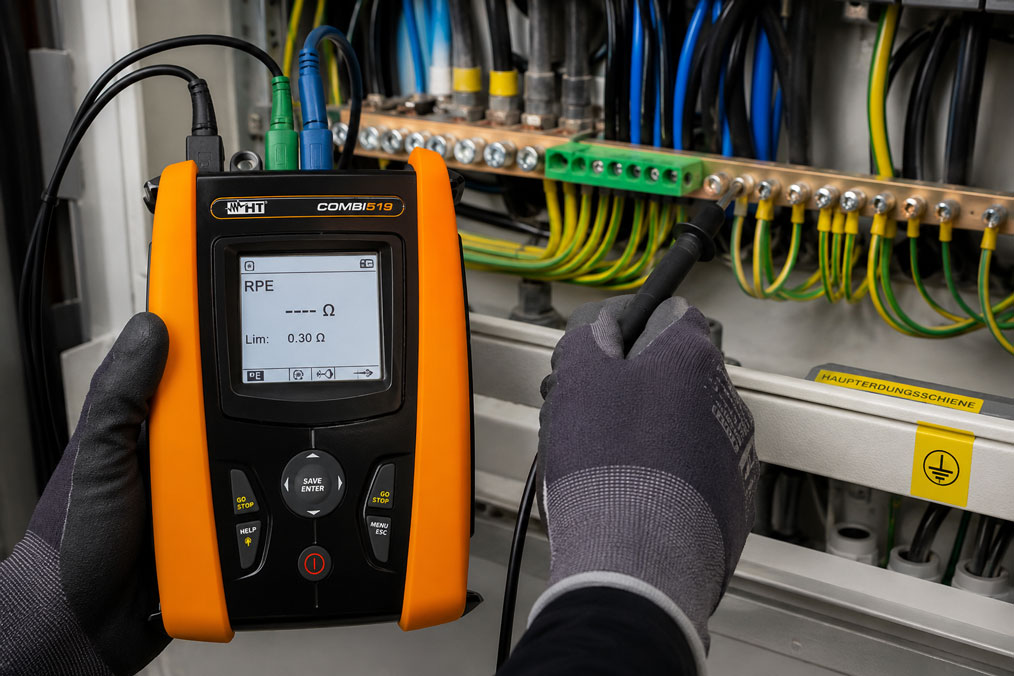
Protective conductor testing is one of the most important tests for electrical installations, machines and devices. It is intended to ensure that exposed conductive parts are reliably connected to the protective conductor. In the event of a fault, the protective conductor must be able to safely carry a dangerous fault current so that protective devices trip and no dangerous touch voltage remains on the enclosure, machine frame or system component.
The focus here is on low-resistance measurement. It checks whether the connection between the protective conductor terminal, protective contact, enclosure, conductive machine part or equipotential bonding connection is present with a sufficiently low resistance. Even small contact resistances, loose terminals, damaged conductors, corroded connections or poorly mounted connections can become safety-critical in the event of a fault.
This article explains why protective conductor testing is so important, how low-resistance measurement basically works and which typical errors occur in practice. The focus is on protective conductor resistance, test current, contact resistances, long cables, sockets, machines, test report, test probes, test leads, equipotential bonding and suitable test instruments such as COMBI519, EASYTEST and C.A 6163.
Table of contents
- Basics: what is the purpose of protective conductor testing?
- Low-resistance measurement: why small resistances are safety-relevant
- Test current: why not just “any continuity” is checked
- Measuring points: where the protective conductor must be tested
- Contact resistances, terminals and contact problems
- Correctly evaluating long cables and large installations
- Protective conductor testing on sockets and circuits
- Protective conductor testing on machines and control cabinets
- Test leads, test probes and zero adjustment
- Test report: documenting measurement results traceably
- Typical errors during protective conductor testing
- Practical example: loose PE terminal in a machine
- Which measuring instruments / products are suitable?
- Conclusion: protective conductor testing is more than a continuity test
- FAQ: frequently asked questions about protective conductor testing
Basics: what is the purpose of protective conductor testing?
The protective conductor is a central part of the protection concept in electrical installations, machines and devices. It connects exposed conductive parts to the protective potential. If a fault occurs, for example if an active conductor touches a metal enclosure, the fault current should flow via the protective conductor. This allows fuses, circuit breakers or residual current devices to react accordingly.
The protective conductor test is intended to verify that this connection is actually present and electrically sufficiently low-resistance. It is not enough for a green-yellow conductor to be visually present. What matters is whether the entire connection from the protective conductor terminal to the exposed conductive part works reliably.
In practice, protective conductor connections can be impaired by installation errors, loose terminals, paint layers, corrosion, damaged cables, plug connections, movable machine cables or subsequent modifications. It is particularly critical that such faults often remain unnoticed during normal operation. The system appears to function correctly, although a dangerous condition can occur in the event of a fault.
Protective conductor testing is therefore not merely a formal measurement for the test report. It is a direct safety test. It answers the question of whether the protective conductor can fulfill its purpose in the event of a fault. This is exactly why low-resistance measurement is an indispensable part of VDE tests, machine tests and equipment tests.
| Test objective | Meaning | Practical relevance |
|---|---|---|
| Verify protective conductor connection | Exposed conductive parts must be connected to PE | Basis for protection against electric shock. |
| Check low resistance | Fault current must be able to flow safely | Loose or poor contacts become detectable. |
| Detect installation errors | Incorrect or missing PE connections can be discovered | Important after new installation, modification or repair. |
| Find mechanical weak points | Movable cables, terminals and plug connections can be critical | Particularly relevant for machines and devices. |
| Document the test | Measurement result must remain traceable | Important for test report, repeat testing and proof of compliance. |
Low-resistance measurement: why small resistances are safety-relevant
Low-resistance measurement measures a very small resistance. This may sound unspectacular at first, but it is decisive from a safety point of view. In the event of a fault, the protective conductor must not represent a high resistance, but must provide a reliable connection to the protective potential. The poorer this connection is, the more unfavorable the fault situation can become.
A high contact resistance can have various causes. A terminal may not be tightened correctly, a conductor may only be partially contacted, a screw connection may sit on paint instead of bare metal, a plug contact may be contaminated or a cable may be damaged. Such faults cannot always be reliably detected by visual inspection alone.
Low-resistance measurement does not only check whether a connection exists at all, but how good this connection is electrically. This is exactly the difference compared to a simple continuity test with a buzzer. A buzzer often indicates continuity even at relatively high resistance values. This statement is not sufficient for protective conductor testing.
In practice, the measured value should always be evaluated in connection with cable length, cross-section, measuring point, contact quality and test task. A long protective conductor naturally has a higher resistance than a short connection in a control cabinet. The decisive factor is therefore not just the number on the display, but the technical plausibility of the measured value.
Test current: why not just “any continuity” is checked
A protective conductor test is carried out using a suitable test instrument and a defined test procedure. The test current is important because a protective conductor connection should not only be assessed under ideal, almost no-load conditions. Contact resistances, poor contacts or unstable connections can behave differently under test current than during a very weak continuity test.
Depending on the test task, standard reference and device type, different test currents may be used. The requirements and test procedures differ for electrical installations, machines and portable equipment. It should therefore always be clear which type of object is being tested and according to which test framework the work is being carried out.
The test current helps make contact problems more visible. A loose terminal may appear inconspicuous during a simple continuity test, but show increased or fluctuating values during a proper low-resistance measurement. Oxidized contacts or poor plug connections can also become noticeable in this way.
It is important that the test current matches the measurement task and the test instrument. An installation tester for electrical installations is designed differently from a machine tester for tests according to the Machinery Directive or EN 60204-1, or an appliance tester for portable equipment. The selection of the test instrument should therefore always match the test task.
| Test aspect | Why important? | Typical practical question |
|---|---|---|
| Test current | Loads the connection during measurement | Does the test procedure match the test object? |
| Measuring range | Low-resistance values must be measured accurately | Can the device reliably display small resistances? |
| Test lead compensation | Lead resistance must not falsify the measurement result | Was zeroing or compensation performed before measurement? |
| Contacting | Poor contact at the test probe causes measurement errors | Is the test probe applied securely and cleanly? |
| Evaluation | Measured value must match the object | Is the value plausible for cable length and cross-section? |
Measuring points: where the protective conductor must be tested
The protective conductor test must be carried out on the relevant exposed conductive parts. These can include protective contacts of sockets, enclosures of equipment, machine frames, control cabinet doors, mounting plates, motor housings, conductive covers, PE bars, equipotential bonding connections or other metallic parts that could become dangerous in the event of a fault.
It is important not to measure only at the nearest protective conductor terminal. The measurement must verify that the actual connection to the exposed part is reliable. For example, a control cabinet door may have a protective bonding strap, but it may be loose, damaged or poorly contacted. A measurement only at the PE bar would not detect this fault.
On machines and systems, movable or removable parts must also be considered. Doors, flaps, protective devices, motors on movable assemblies or pluggable system parts may require their own protective conductor connections. Faults occur particularly at these points due to movement, vibration, modifications or mechanical stress.
The selection of measuring points should therefore be made from the perspective of the user and the fault case. Where can a person touch a conductive part? Which parts could become live in the event of an insulation fault? Which connections are mechanically stressed or retrofitted? These questions help plan the measurement sensibly.
Contact resistances, terminals and contact problems
Contact resistances occur at connection points. These can be screw terminals, plug contacts, crimp connections, earthing straps, hinges, enclosure connections, mounting plates, painted surfaces or clamping points. Each of these points can increase the protective conductor resistance if it is not executed correctly.
A common practical error is painted or coated metal parts. If a protective conductor connection is mounted on a coated surface, the electrical contact may be poorer than expected. The same applies to contaminated contact surfaces, corrosion or insufficiently tightened screws. Mechanically, the connection often looks stable, but electrically it is not reliable.
Vibration can also be problematic. In machines, pumps, compressors or systems with moving parts, terminals can become loose. A recurring protective conductor test can make such changes visible. Fluctuating measured values during slight movement of the cable or door are a clear indication of contact problems.
Low-resistance measurement helps systematically find such faults. If a measured value is significantly higher than expected, not only the conductor itself should be considered. The cause is often at a contact point. A targeted test along the protective conductor connection can narrow down the fault.
| Contact point | Possible problem | Test approach |
|---|---|---|
| Screw terminal | Loose, not correctly tightened or conductor not inserted cleanly | Check terminal and retighten / measure again. |
| Control cabinet door | Earthing strap missing, damaged or poorly contacted | Measure from PE bar to door or door component. |
| Painted surface | Poor metallic contact | Check contact surface and fastening design. |
| Plug connection | Wear, contamination or contact spring problem | Move plug connection and observe measured value. |
| Equipotential bonding strap | Mechanically damaged or corroded | Combine visual inspection and low-resistance measurement. |
Correctly evaluating long cables and large installations
With long cables, the protective conductor resistance is higher than with short connections. This is initially normal because every conductor has electrical resistance. The measured value must therefore always be considered in connection with cable length, cross-section, material and measurement path. A general comparison between a short control cabinet connection and a long cable to a distant socket is not meaningful.
In large installations, the measurement can also be influenced by long test leads, extensions or unfavorable contacting. Correct test lead compensation is therefore particularly important. If the resistance of the test leads is not compensated, it is added to the actual protective conductor resistance and can falsify the result.
At distant measuring points, it should also be ensured that the measurement path is clear. In branched installations, parallel connections, equipotential bonding systems or metallic structures can influence the measurement result. This is not fundamentally wrong, but it must be understood when evaluating a measured value.
In practice, this means: the larger and more complex the installation, the more important measurement planning, clear measuring points and proper documentation become. The measured value alone is not sufficient if it is later no longer possible to trace between which points the measurement was taken.
Protective conductor testing on sockets and circuits
Protective conductor testing is particularly important on sockets because a wide range of equipment is connected there. A missing or poor protective conductor at the protective contact can mean that connected devices are not sufficiently protected in the event of a fault. It must therefore be checked whether the protective contact is reliably connected to the protective conductor.
When testing circuits, measurements are often taken from the protective contact or a suitable measuring point to the protective conductor or PE bar. Loose terminal points, interrupted PE conductors, incorrect wiring or poor contacts can be detected in this way. In existing installations, such faults are particularly relevant when sockets have been retrofitted, extended or modified.
A simple socket indicator does not fully replace protective conductor testing. A basic socket tester can provide indications of major wiring faults, but it does not necessarily measure the protective conductor resistance under suitable conditions. A suitable test instrument is required for a standards-compliant test.
Multiple sockets, extension leads and portable consumers should also not be considered uncritical across the board. Movable cables and frequently used plug connections are mechanically stressed. Visual inspection and protective conductor testing complement each other well here.
Protective conductor testing on machines and control cabinets
On machines and control cabinets, protective conductor testing is particularly extensive because many conductive parts may be present. These include control cabinet enclosures, mounting plates, doors, control panels, motors, pumps, drives, protective covers, cable ducts, conductive structural parts and external system components. Not every part is automatically sufficiently connected to the protective conductor.
Machines are often mechanically stressed. Vibrations, movement, maintenance work, modifications or replacement of components can influence protective conductor connections. Door earthing, motor connections, plug connectors and movable assemblies should be checked particularly carefully.
In control cabinets, it should also be noted that a stable PE bar alone is not sufficient. The connection from the PE bar to all relevant conductive parts must be verified. Otherwise, a painted mounting surface, a loose earthing strap or a poorly conductive hinge connection may remain undetected.
Machine testers are often used for machine tests, covering other electrical safety tests in addition to protective conductor testing. These may include insulation testing, high-voltage testing, leakage current measurement, functional testing and documentation. Protective conductor testing remains one of the central foundations.
Test leads, test probes and zero adjustment
During low-resistance measurement, test leads and test probes can have a considerable influence on the result. Because very small resistances are measured, the resistance of the test leads is also significant. For this reason, many test instruments offer a zero adjustment or test lead compensation function.
Before measurement, the test leads should be checked for damage, loose plugs, broken conductors and clean contacts. A damaged test lead can not only generate false values, but also represent a safety risk. Test probes must sit securely on the measuring point and must not just randomly touch a conductive point.
Contact force also plays a role. If the test probe is placed on a contaminated, oxidized or painted surface, a high contact resistance can occur that does not belong to the actual protective conductor connection. Conversely, the measurement must not be artificially improved by heavy scratching or accidentally penetrating a coating if the actual connection is not reliable during operation.
For repeatable measurements, measuring point, test probe, contacting and test lead compensation should be carried out as consistently as possible. Only in this way can results be meaningfully compared and documented.
| Influencing factor | Possible effect | Recommendation |
|---|---|---|
| Test lead resistance | Measured value is displayed too high | Compensate test leads before measurement. |
| Contaminated test probe | Poor contact and fluctuating values | Check test probes and keep them clean. |
| Painted surface | Contact resistance falsifies result | Use suitable measuring point and evaluate design. |
| Loose test lead | Unstable or jumping values | Check leads and plugs before use. |
| Wrong measuring range | Insufficient resolution or misinterpretation | Use the low-resistance measurement function of the test instrument. |
Test report: documenting measurement results traceably
The protective conductor test must not only be performed, but also documented in a traceable way. A test report should show which object was tested, which measuring points were used, which test instrument was used, which measured value was obtained and how the result was evaluated.
Especially for larger installations, machines or recurring tests, clear assignment is important. A single value without measuring point description is hardly meaningful later. If, however, it is documented that measurement was taken, for example, from the PE bar to the control cabinet door, to the motor housing or to a specific socket, the condition can later be traced much better.
Test instrument, serial number, calibration status and test date should also be documented. In many companies, this information is important for internal quality assurance, audits, maintenance and legally reliable proof. Modern test instruments can store measured values and later transfer them to test software or reports.
In the case of conspicuous measured values, it should also be noted which measure was taken. Was a terminal retightened? Was a protective conductor replaced? Was a measurement repeated? Such information helps use the test not only as a snapshot, but as part of maintenance.
Typical errors during protective conductor testing
A common error is confusing visual inspection with protective conductor testing. A visible PE conductor does not automatically mean that the connection is electrically faultless. Low-resistance measurement is necessary to actually evaluate the connection.
A simple continuity test with a buzzer is also problematic. A buzzer can indicate continuity even though the resistance for a protective conductor connection is too high or the contact point is unstable. A suitable low-resistance measurement procedure is required for a professional evaluation.
Another error is missing compensation of the test leads. Especially with small resistances, lead resistance can significantly influence the result. Anyone using long test leads must work particularly carefully and document the measurement setup.
Incorrect measuring points also lead to incomplete results. If measurements are only taken at the PE bar, but not at the door, enclosure, motor or conductive system part, critical faults may remain undetected. The measuring points must match the actual touchable parts and the protection concept.
| Error pattern | Possible cause | Test approach |
|---|---|---|
| Measured value is higher than expected | Loose terminal, long cable, poor contact or test lead resistance | Divide measurement path and compensate test leads. |
| Measured value fluctuates | Unstable contact point, movable cable or poor test probe | Check contacting and mechanical stress. |
| Buzzer indicates continuity, low-resistance measurement is conspicuous | Continuity exists, but resistance or contact quality is insufficient | Use low-resistance measurement as the decisive test. |
| Control cabinet door is not safely connected | Earthing strap missing, loose or poorly contacted | Measure directly on the door or door component. |
| Test report is not traceable | Measuring points or test conditions not documented | Clearly record measuring point, device, value and evaluation. |
Practical example: loose PE terminal in a machine
During the recurring test of a production machine, the protective conductor connection between the PE bar in the control cabinet and several exposed metal parts is checked. The visual inspection initially shows no abnormalities. All green-yellow conductors are present, and the machine operates without malfunction during normal operation.
During low-resistance measurement, however, it becomes apparent that the resistance to the housing of a drive motor is higher than expected and fluctuates when the cable is moved slightly. The measurement is repeated, the test leads are compensated and the measuring point directly on the motor housing is tested again. The behavior remains conspicuous.
After opening the terminal box, a PE terminal that was not sufficiently tightened is found. Mechanically, the conductor was still present, but electrically the connection was not reliable. After proper fastening, the measurement is performed again. The value is now stable and significantly more plausible.
The example shows why protective conductor testing cannot be replaced by a visual inspection. Loose terminals, damaged connections or unstable contacts often only become visible through proper low-resistance measurement.
Which measuring instruments / products are suitable?
For protective conductor testing in electrical installations, the COMBI519 installation tester is a suitable solution. It is suitable for testing electrical systems and installations and supports typical measurement tasks as part of installation testing. Depending on the test sequence, this also includes measurements relevant to evaluating protective measures.
The EASYTEST installation tester is interesting when recurring test sequences in electrical installations need to be carried out as simply and structurally as possible. For field installation testing, ease of use, automatic measurement sequences and reliable assignment of measurement results are particularly important.
For machines and electrical equipment, the C.A 6163 multitester / machine tester is suitable. It is particularly relevant when protective conductor testing, machine testing, documentation and accessory integration are to be combined in a professional test sequence.
Which solution is suitable depends on the test task. An electrical building installation requires different test sequences than a machine or portable device. The decisive factors are standard reference, test current, measuring range, test lead accessories, memory function, report generation and practical handling at the measuring point.
| Product / area | Typical use | Particularly relevant for |
|---|---|---|
| COMBI519 installation tester | Testing electrical systems and installations | VDE testing, circuits, sockets, distribution boards and installation testing |
| EASYTEST installation tester | Structured installation testing in the field | Recurring test sequences, service calls and easy operation |
| C.A 6163 multitester / machine tester | Testing electrical machines and equipment | Machine testing, protective conductor testing, documentation and accessory integration |
| Suitable test leads and test probes | Safe contacting during low-resistance measurements | Long measurement paths, difficult-to-access points and repeatable measurements |
| Test software / documentation | Storage and evaluation of measurement results | Test reports, recurring tests, audits and maintenance |
Conclusion: protective conductor testing is more than a continuity test
Protective conductor testing is one of the most important safety tests on electrical installations, machines and devices. It ensures that exposed conductive parts are reliably connected to the protective conductor and that safe discharge is possible in the event of a fault. A simple visual inspection or continuity buzzer is not sufficient for this.
Low-resistance measurement shows whether the protective conductor connection is electrically sufficiently low-resistance and stable. It makes loose terminals, poor contacts, damaged cables, contact resistances and insufficient connections visible. Careful measurement is particularly important with long cables, machines, control cabinets, sockets and movable system parts.
The most important recommendation is: always understand protective conductor testing as a combination of visual inspection, suitable low-resistance measurement, correct measuring points and clean documentation. Only then is reliable proof created that the protective conductor can actually fulfill its safety function.
FAQ: frequently asked questions about protective conductor testing
What is a protective conductor test?
The protective conductor test checks whether exposed conductive parts are reliably connected to the protective conductor. It is important for preventing dangerous touch voltages in the event of a fault.
Why is protective conductor testing important?
A damaged or interrupted protective conductor can cause a metal enclosure to become live in the event of a fault. Protective conductor testing helps detect such dangerous conditions at an early stage.
What does low-resistance measurement mean?
Low-resistance measurement means measuring very small resistances. In protective conductor testing, it is used to evaluate whether the connection between protective conductor and exposed conductive part is sufficiently low-resistance.
Is a simple continuity test sufficient?
No. A simple continuity test only shows that some kind of connection exists. It does not reliably evaluate whether resistance and contact quality are sufficient for a protective conductor connection.
Why is measurement performed with test current?
The test current loads the connection during measurement and helps detect poor or unstable contacts more effectively. This makes the test more meaningful than a pure continuity indication.
Which measuring points are important?
Measurements should be taken on the relevant exposed conductive parts, for example protective contact, enclosure, control cabinet door, motor housing, machine frame or equipotential bonding connection.
Why must the control cabinet door be tested?
A control cabinet door can be touched and may contain conductive parts. If the earthing strap is missing, loose or poorly contacted, the door can become dangerous in the event of a fault.
What causes high protective conductor resistances?
Possible causes include loose terminals, long cables, poor contacts, corrosion, damaged conductors, paint layers, contaminated contact surfaces or defective plug connections.
Why does the measured value sometimes fluctuate?
Fluctuating values often indicate unstable contacts, movable cables, poor test probes or loose terminals. The measuring point should then be examined more closely.
Why is test lead compensation important?
During low-resistance measurements, the resistance of the test leads is relevant. Without compensation, it can be added to the measurement result and make the protective conductor resistance appear too high.
How do you evaluate long protective conductor connections?
Long cables naturally have higher resistance. The measured value must therefore be evaluated in connection with cable length, cross-section, material and measurement path.
Can visual inspection replace measurement?
No. Visual inspection is important, but it does not detect all electrical contact problems. A loose or poorly contacted connection may be visually inconspicuous.
What must be included in the test report?
The test report should include test object, measuring point, measured value, test instrument, date, evaluation and, if applicable, corrective actions. Only in this way does the test remain traceable.
Which test instrument is suitable for installations?
Installation testers such as COMBI519 or EASYTEST are suitable for electrical installations. They support typical test sequences as part of installation testing.
Which test instrument is suitable for machines?
A machine tester such as the C.A 6163 is suitable for machines and electrical equipment. It is designed for extensive test sequences on machines and their documentation.
What is the difference between protective conductor testing and loop impedance measurement?
Protective conductor testing evaluates the low-resistance connection of the protective conductor. Loop impedance measurement, on the other hand, considers the fault current loop and the disconnection conditions of a circuit.
When should a protective conductor test be carried out?
It is carried out during initial testing, repeat testing, after repairs, modifications, extensions or if a protective conductor fault is suspected. The exact test framework depends on the object and applicable requirements.
What is the most important practical rule?
Always measure on the actually exposed conductive parts, compensate test leads, evaluate contact points carefully and document the measurement results clearly.