


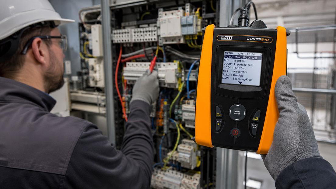
In practice, VDE tests are not only carried out in new, clearly documented installations. Very often, electrical installations have to be tested that have grown over many years. Old distribution boards, later extensions, unclear network systems, mixed circuits, missing labels, modified protective measures and incomplete documentation are part of everyday work. In exactly these existing installations, it is often not enough to simply read measured values and compare them with a limit value.
Unclear N/PE connections, previous PEN splitting points, retrofitted RCDs, old sub-distribution boards, provisional extensions or modifications where the originally intended protective measure can no longer be clearly traced are particularly critical. An installation tester provides important measured values, but the technical assessment must be carried out by qualified electrical personnel. Only those who correctly classify the network system, installation condition, protective measure and measuring method can draw the right conclusions from the measured values.
This article explains what must be considered when carrying out VDE testing in existing installations, why old electrical installations often require more diagnostics than new installations and how installation testers can help with assessment. The focus is on old distribution boards, N/PE bridges, later modifications, mixed circuits, missing documentation, protective conductor testing, insulation measurement, loop impedance, RCD testing, interpretation of measured values and safe working by qualified personnel.
Table of contents
- Basics: why existing installations must be tested differently
- Work and assessment only by qualified personnel
- Missing documentation: checking circuit diagrams, circuits and labels
- Unclear network system: correctly classifying TT, TN, TN-C, TN-S and IT
- N/PE bridges and PEN splitting: typical faults in existing installations
- Old distribution boards and later extensions
- Important measurements: protective conductor, insulation, loop, RCD and voltage drop
- Correctly interpreting measured values: why a single value is rarely enough
- Modifications, changes of use and altered protective measures
- Practical example: RCD trips, cause is an old N/PE connection
- Which measuring instruments / products are suitable?
- Conclusion: existing installations require measurement, diagnostics and expert assessment
- FAQ: frequently asked questions about VDE testing in existing installations
Basics: why existing installations must be tested differently
Ideally, a new electrical installation is built according to the current planning status, fully documented, clearly labeled and then tested in a structured manner. In existing installations, the situation is often much more complex. Circuits have been extended, distribution boards modernized, individual rooms repurposed, old cables reused or protective devices retrofitted. The result is an installation that works technically, but is not always immediately understandable.
When carrying out a VDE test on an existing installation, it must first be understood what is actually present. Which network system is in place? Where was a PEN conductor split? Are there old two-wire cable sections? Are neutral conductors and protective conductors properly separated? Which circuits are routed through which RCD? Do the labels match the actual wiring? Have loads or sub-distribution boards been added later?
An installation tester can provide many important measured values, for example protective conductor resistance, insulation resistance, loop impedance, line impedance, RCD tripping time, RCD tripping current, phase sequence, voltage and voltage drop. The challenge, however, lies in evaluating these measured values in relation to the existing installation. In existing installations, the same measured value can be interpreted differently depending on the network system, cable length, protective device and installation structure.
Testing an existing installation is therefore often more diagnostic work than a pure measurement routine. Automatic test sequences and stored measured values are helpful, but they do not replace technical assessment. Especially in old or modified installations, the tester must recognize whether an implausible measured value is caused by a real fault, an incorrect measuring point, an old installation structure or unsuitable documentation.
| Characteristic in existing installations | Typical problem | Why important for testing? |
|---|---|---|
| Grown installation | Circuits have been extended or changed over many years | Measured values must match the actual wiring, not only the old plan. |
| Unclear network system | TT, TN-C, TN-S or mixed forms are not clearly recognizable | Protective measure and measuring method must be assessed correctly. |
| N/PE connections | Neutral conductor and protective conductor are connected at an unexpected point | RCD function, insulation measurement and fault diagnostics can be affected. |
| Missing labels | Circuits, RCD assignment or sub-distribution boards are unclear | Measured values can be assigned incorrectly or documented incompletely. |
| Later modifications | New loads were connected to old cables or distribution boards | Current-carrying capacity, protective measure and disconnection conditions must be reassessed. |
Work and assessment only by qualified personnel
Tests on electrical installations may only be carried out and assessed by qualified personnel. This applies especially to existing installations, because the hazards present are not always immediately visible. Old cables, damaged insulation, unclear protective conductor connections, incomplete disconnections, parallel supplies, stored energy or faulty modifications can create significant risks.
An installation tester is a powerful tool, but it is not a substitute for technical expertise. The device can perform a measurement and display values. However, it does not automatically decide whether the entire installation is safe, whether the measurement was carried out at the correct point or whether the protective measure matches the existing network system. This assessment must be performed by a qualified electrician.
Particular caution is required with N/PE problems, PEN splitting points, retrofitted RCDs or unclear distribution board structures. Incorrect assumptions can lead to a fault being overlooked or a measured value being interpreted incorrectly. Disconnecting neutral conductors, disconnecting loads or rewiring for testing purposes may also only be carried out professionally and in compliance with safety rules.
In practice, this means: before measuring, it must be clear which installation is being tested, which hazards exist, which protective measure is expected and which measurement is permissible. After the measurement, it must be assessed whether the measured value matches the installation. Especially in the case of deviations, one single component should not be blamed too quickly. The cause often lies in the structure of the existing installation.
Missing documentation: checking circuit diagrams, circuits and labels
Complete documentation is often not available in existing installations. Circuit diagrams are missing, distribution board labels are outdated, circuit lists have not been updated or modifications are only partially documented. As a result, a circuit may be assigned to one room in the plan, but actually supply additional loads. RCD assignments in old distribution boards also do not always match the labeling.
Before the actual measurement, it should therefore be checked whether the existing documentation is plausible. Do circuit numbers and fuse labels match? Are sub-distribution boards clearly assigned? Are there signs of later extensions? Have old miniature circuit breakers been replaced? Have RCDs been retrofitted? Are there terminals, bridges or provisional wiring that are not documented?
Missing or incorrect documentation is not only an organizational problem. It directly affects the measurement. If a circuit is assigned incorrectly, a measured value can end up in the wrong place in the test report. If loads are not known, insulation measurements may be impermissible or not meaningful. If RCD assignments are unclear, troubleshooting in the event of tripping becomes much more difficult.
VDE testing in existing installations should therefore always also be understood as a documentation-related task. Findings, deviations between plan and reality, unclear circuits and later additions should be recorded. Good documentation after testing greatly simplifies later maintenance, modifications and periodic inspections.
Unclear network system: correctly classifying TT, TN, TN-C, TN-S and IT
The network system is a central basis for assessing an electrical installation. In new installations, it is usually clearly documented. In existing installations, however, it can be unclear, especially when old installation parts have been combined with new distribution boards. In practice, transitions between TN-C and TN-S, local earth electrodes, old PEN conductors, retrofitted RCDs or partial modifications can make assessment more difficult.
In TN-C systems, neutral conductor and protective conductor functions are combined in one PEN conductor. From the point where it is split into N and PE, these conductors must not be arbitrarily reconnected in the following TN-S section. In existing installations, however, unexpected connections, bridges or shared conductor sections are repeatedly found, which can become problematic when an RCD is retrofitted later.
In TT systems, the consumer’s earthing system is an essential part of the protective measure. Earth resistance, RCD function and disconnection conditions play a different role here than in a TN system. A measured value that is plausible in one network system may be critical in another. Therefore, before assessment, it must be clear which network system is actually present.
IT systems or special networks can also occur in industry, medical facilities, laboratories or certain technical systems. Different diagnostic and monitoring approaches apply there. If the network system is unclear, a standard test sequence should not simply be processed. First, the installation structure must be clarified by a qualified person.
| Network system / situation | Typical characteristic | Relevance for testing |
|---|---|---|
| TN-C | PEN conductor combines neutral and protective conductor function | Splitting and further conductor routing must be assessed clearly. |
| TN-S | N and PE are routed separately | Impermissible N/PE connections after the split can influence RCDs. |
| TT | Protective measure depends strongly on earthing and RCD | Earthing system, RCD function and disconnection conditions must be assessed together. |
| IT | First fault does not automatically lead to disconnection | Insulation monitoring and installation concept are particularly important. |
| Mixed existing structure | Old and new installation parts are combined | Measuring method and assessment must match the actual structure. |
N/PE bridges and PEN splitting: typical faults in existing installations
N/PE connections are among the most common and at the same time most demanding topics in grown electrical installations. A connection between neutral conductor and protective conductor can be present at certain points due to the system, for example in connection with PEN splitting. At other points, however, such a connection can be a fault, especially if it occurs downstream of an RCD or in an already separated TN-S section.
An unexpected N/PE connection can have various effects. RCDs can trip for no clearly recognizable reason. Parts of the operating current can flow through protective conductors or extraneous conductive parts. Insulation measurements can produce implausible results. Even with disconnected circuits, feedback effects from other circuits can still occur. In existing installations with several distribution boards, the cause is often not immediately recognizable.
Retrofitted RCDs in old distribution boards are particularly critical. If neutral conductors from different circuits are routed together or mixed downstream of different RCDs, the installation may appear to work in normal operation, but trip under certain load conditions or during testing. Old bridges, shared neutral conductors or incorrectly assigned N bars can also cause faults.
Searching for N/PE connections is not merely a device function, but a systematic diagnostic task. It requires knowledge of the network system, distribution board structure, RCD assignment and connected loads. An installation tester can provide important indications through insulation measurements, low-resistance measurements, loop measurements and RCD tests. However, interpretation must be carried out professionally.
Old distribution boards and later extensions
Old distribution boards often show a mixture of the original installation and later changes. Miniature circuit breakers were replaced, RCDs added, circuits combined, new loads connected or sub-distribution boards retrofitted. Sometimes spare positions were used without updating the documentation. In other cases, old cables were retained even though the use of the area changed significantly.
When testing such distribution boards, not only the function of individual circuits should be considered. The structure is also important: are N bars and PE bars properly separated? Are RCD groups clearly structured? Are conductor cross-sections and protection plausible? Are terminals tight and suitable? Are there thermal marks, discoloration, mechanical damage or provisional wiring?
Later extensions can cause old circuits to be loaded more heavily than originally intended. A former lighting circuit may supply additional socket outlets. An old sub-distribution board may supply new machines or IT loads. A distribution board may contain several phases of modification that were technically understandable individually, but have become confusing in the overall picture.
In existing installations, visual inspection is therefore particularly important. It provides indications that no measured value alone can detect. An installation tester shows electrical measured values, but loose terminals, incorrectly labeled circuits, mechanically damaged cables or unclear bridges are often first detected by carefully inspecting the distribution board.
Important measurements: protective conductor, insulation, loop, RCD and voltage drop
The choice of measurements depends on the installation, network system, protective measure and test task. In existing installations, protective conductor testing, insulation measurement, loop impedance or line impedance, RCD testing, phase sequence testing and voltage measurement are particularly relevant. Depending on the installation, additional measurements may be required, such as earth measurement, voltage drop or power quality assessment.
The protective conductor test shows whether protective conductor connections are low-resistance and continuous. In existing installations, increased values can result from long cables, poor terminal connections, corrosion, damaged connections or incorrect assignment. A conspicuous value must therefore not only be measured, but also localized on site.
Insulation measurement is particularly important, but often demanding in existing installations. Connected loads, electronic devices, surge protection, control systems, dimmers, frequency converters or luminaires can influence the measurement or be damaged by unsuitable test voltage. Before measuring, it must therefore be clear which equipment is connected and how the measurement may be carried out correctly.
Loop impedance, line impedance and short-circuit current indication help assess disconnection conditions. In old installations, long cable routes, poor connections or unsuitable protective devices may become apparent. RCD tests are particularly important when residual current devices have been retrofitted or several circuits are routed through shared protective devices.
| Measurement | Use in existing installations | Typical finding |
|---|---|---|
| Protective conductor resistance / low resistance | Checks continuity of protective conductors and connections | Increased values due to terminals, corrosion or long cable routes. |
| Insulation measurement | Detects insulation faults and unintended connections | Implausible values due to connected loads or N/PE connections. |
| Loop impedance / line impedance | Helps assess disconnection conditions | High impedance due to long cables or poor contact points. |
| RCD testing | Assesses tripping behavior of residual current devices | Tripping due to mixed neutral conductors or N/PE bridges. |
| Phase sequence and voltage | Checks supply, assignment and phase sequence | Incorrect assignment after modifications or swapped phase conductors. |
Correctly interpreting measured values: why a single value is rarely enough
In existing installations, a measured value should never be considered in isolation. An increased protective conductor resistance can indicate a fault, but may also be explained by long cable routes. A low loop impedance may be plausible, but alone says nothing about clean separation of N and PE. A tripping RCD can indicate a defective load, incorrect N assignment or an N/PE connection.
The combination of measured values, visual inspection and understanding of the installation is important. If an RCD trips during a certain measurement, it should be checked whether the measurement matches the RCD group, whether neutral conductors are assigned correctly and whether connected equipment influences the measured value. If an insulation measurement is conspicuous, it must be clarified whether loads were connected or whether a real insulation weakness is present.
An installation tester with memory function and structured test sequences can help record measured values in an organized way. Nevertheless, room for diagnostics should remain in existing installations. Automatic sequences are very useful for repeatable test procedures, but they cannot automatically explain implausible installation conditions. The tester must decide when a measurement must be repeated, supplemented or assessed differently.
Correct interpretation also includes documenting boundary conditions. Was the measurement carried out with or without connected loads? Which RCD group was affected? Was the installation partially disconnected? Were neutral conductors disconnected? Were any findings observed in the distribution board? Such information is often crucial later in order to understand measured values.
Modifications, changes of use and altered protective measures
Many existing installations have not only been repaired over time, but functionally changed. Storage areas became offices, apartments became commercial spaces, simple machine connections became complex production areas. With every change of use, the requirements for electrical supply, protective measures, residual current protection, selectivity, documentation and current-carrying capacity often change as well.
Later modifications are particularly critical when new protective measures meet old installation parts. A retrofitted RCD can make old N/PE connections visible. New electronic loads can increase leakage currents. Frequency converters, switching power supplies or charging equipment can place different requirements on RCD type, power quality and protection concept. An installation that was previously inconspicuous can suddenly show problems after a modification.
During testing, it should therefore be asked whether the installation still matches its current use. Are cable lengths, protective devices and cross-sections suitable for today’s loads? Have suitable RCDs been selected? Are there circuits that are more heavily loaded by new loads? Are old distribution boards sufficiently documented and labeled for the new use?
A VDE test cannot answer these questions through individual measured values alone. However, it provides important indications. Conspicuous voltage drops, high loop impedances, RCD problems, implausible insulation values or strongly deviating measured values between similar circuits can show that an existing installation needs closer examination.
Practical example: RCD trips, cause is an old N/PE connection
A periodic inspection is carried out in an older commercial building. Several circuits were extended a few years ago, and RCDs were retrofitted in a sub-distribution board. The documentation is incomplete, and the labeling of the neutral conductor bars is partly unclear. In normal operation, it is initially only noticed that an RCD trips occasionally without a specific load being clearly identifiable as the cause.
During testing, individual measured values show a contradictory picture. The protective conductor test is plausible at several measuring points, but unexpected tripping occurs during RCD testing. In addition, some insulation measurements appear ambiguous. Instead of immediately assessing the RCD as defective, the distribution board structure is examined more closely.
It turns out that in an older circuit there is a connection between neutral conductor and protective conductor that no longer matches the new protective structure after the later RCD retrofit. In addition, neutral conductors from different circuits are not clearly assigned separately. In normal operation, the fault only occurs under certain load conditions, but it becomes visible during testing.
After professional clarification of the circuit assignment, correction of the N/PE problem and updating of the documentation, the measurements are repeated. The RCD test is now traceable, and the measured values can be assigned cleanly. The example shows: in existing installations, a conspicuous measured value is often the starting point for diagnostics, not immediately the complete explanation.
Which measuring instruments / products are suitable?
For testing existing installations, an installation tester is required that reliably covers typical measurements for electrical installations. These include low-resistance measurement, insulation measurement, RCD testing, line and loop impedance, short-circuit current indication, phase sequence, voltage measurement and, depending on the application, further functions. The category installation testers / VDE 0100 installation testing is a useful starting point for this.
The COMBI519 installation tester is suitable for comprehensive installation tests and supports important test tasks such as auto sequences, low-resistance measurement, insulation measurement, RCD testing, line and loop impedance, short-circuit current indication, phase sequence and voltage drop. Especially in existing installations, it is helpful to record measured values in a structured way and to carry out targeted supplementary measurements in the event of abnormalities.
The EASYTEST installation tester is interesting when periodic inspections need to be carried out efficiently and with automated procedures. In existing installations, however, an auto sequence should always be used deliberately: it supports the procedure, but does not replace the technical assessment of unclear network systems, old distribution boards or unexpected measured values.
For extended applications, for example in installations with charging infrastructure or additional diagnostic requirements, the COMBI521 installation tester is particularly relevant. In addition to classic installation tests, EVSE test sequences, extended measuring functions and digital documentation may also play a role depending on accessories and application.
| Product / area | Typical use | Particularly relevant for |
|---|---|---|
| COMBI519 installation tester | Comprehensive installation and electrical system testing | Existing installations, RCD testing, loop impedance, insulation measurement, voltage drop and test reports |
| EASYTEST installation tester | Structured VDE testing with auto sequence function | Periodic inspections, mobile use and efficient test procedures |
| COMBI521 installation tester | Extended installation testing including EVSE test sequences | Charging infrastructure, RCD type B / EV, Wi-Fi connection, documentation and additional measurements |
| VDE 0100 / VDE 0105 installation testing | Selection of suitable test instruments for electrical installations | Protective conductor testing, insulation measurement, loop measurement, RCD testing and periodic inspection |
| Test equipment management and calibration | Monitoring of calibration status and readiness for use of test instruments | Testing service providers, electrical contractors, quality management and tests requiring documentation |
Conclusion: existing installations require measurement, diagnostics and expert assessment
VDE testing in existing installations is more demanding than testing a new, fully documented installation. Old distribution boards, grown circuits, later extensions, unclear network systems, N/PE connections and missing documentation require a careful combination of visual inspection, measurement and technical assessment.
Installation testers such as COMBI519, EASYTEST or COMBI521 provide important measured values and support structured test procedures. However, it is crucial that the measured values are understood in the context of the installation. A conspicuous RCD test, an implausible insulation measurement or an increased loop impedance are indications that must be further classified.
The most important recommendation is: do not treat existing installations like ideal new installations. Before assessment, network system, distribution board structure, N/PE assignment, modifications, protective measures and documentation must be clarified. Only then can measured values be interpreted reliably and electrical installations be assessed safely, traceably and professionally.
FAQ: frequently asked questions about VDE testing in existing installations
Why are VDE tests in existing installations more difficult?
Existing installations have often grown over many years. Old distribution boards, modifications, missing documentation, unclear network systems and retrofitted RCDs make assessment more complex than with a newly installed system.
Is anyone allowed to test an existing installation?
No. Work, measurements and assessments on electrical installations may only be carried out by qualified personnel. In existing installations, technical assessment is particularly important because old or unclear structures can create additional risks.
What is particularly critical in old distribution boards?
Critical points include unclear conductor assignments, old bridges, mixed neutral conductors, retrofitted RCDs, missing labels, loose terminals, thermal marks, unsuitable protection and undocumented extensions.
What does N/PE bridge mean?
An N/PE bridge is a connection between neutral conductor and protective conductor. Depending on network system and position, such a connection can be system-related or faulty. An unexpected N/PE connection downstream of an RCD can be particularly problematic.
Why do RCDs in existing installations sometimes trip without a clear cause?
Possible causes include mixed neutral conductors, N/PE connections, defective loads, leakage currents, moisture or incorrect circuit assignment. In existing installations, such faults often only become apparent after modifications or retrofits.
How can an impermissible N/PE connection be detected?
Diagnosis is carried out by technically correct inspection of the installation structure and suitable measurements. This can include visual inspection, insulation measurement, low-resistance measurement, RCD testing and targeted localization of the affected circuits. Assessment depends on the network system and installation structure.
Why is the network system so important?
The network system determines how protective measures work and how measured values must be assessed. TT, TN-C, TN-S and IT systems have different requirements. Without correct network system assessment, measured values can be interpreted incorrectly.
What must be considered when splitting a PEN conductor?
After a PEN conductor has been split into N and PE, neutral conductor and protective conductor must be routed separately in the downstream section. Unexpected reconnections can influence RCDs and protective measures.
Why is missing documentation problematic?
Without correct documentation, circuits, RCD assignments, sub-distribution boards and modifications are difficult to trace. Measured values can be assigned incorrectly, and troubleshooting becomes much more time-consuming.
Which measurements are particularly important in existing installations?
Typical measurements include protective conductor resistance, insulation resistance, loop impedance, line impedance, RCD tripping time, RCD tripping current, voltage, phase sequence and, depending on the installation, voltage drop or earth measurement.
Why is one measured value not enough?
A single measured value only shows one part of the installation. In existing installations, measured values must be assessed together with network system, cable length, protective device, distribution board structure, connected loads and visual inspection.
What can make insulation measurement difficult in existing installations?
Connected loads, electronic devices, surge protection, dimmers, frequency converters, luminaires or control systems can influence insulation measurements or be damaged if the test is performed incorrectly.
Why are retrofitted RCDs often a problem?
Retrofitted RCDs often meet old conductor structures. If neutral conductors are mixed or old N/PE connections exist, the RCD can trip or troubleshooting can become more difficult.
When should an existing installation be examined more closely?
A closer examination is useful in the case of implausible measured values, repeated RCD tripping, unclear network system, missing documentation, old distribution boards, visible damage, modifications or strongly differing measured values between similar circuits.
What role does visual inspection play?
Visual inspection is particularly important because many problems are not immediately apparent from measured values. These include damaged cables, loose terminals, incorrect labels, old bridges, thermal marks or provisional wiring.
Which installation testers are suitable for existing installations?
Suitable installation testers support typical installation tests such as low resistance, insulation, RCD, loop impedance, line impedance, phase sequence, voltage and documentation. Examples include COMBI519, EASYTEST and COMBI521.
Does an auto sequence replace expert assessment?
No. Auto sequences help with structured test procedures, but they do not replace technical assessment. In existing installations, unclear network systems, N/PE problems and modifications must still be assessed by qualified personnel.