


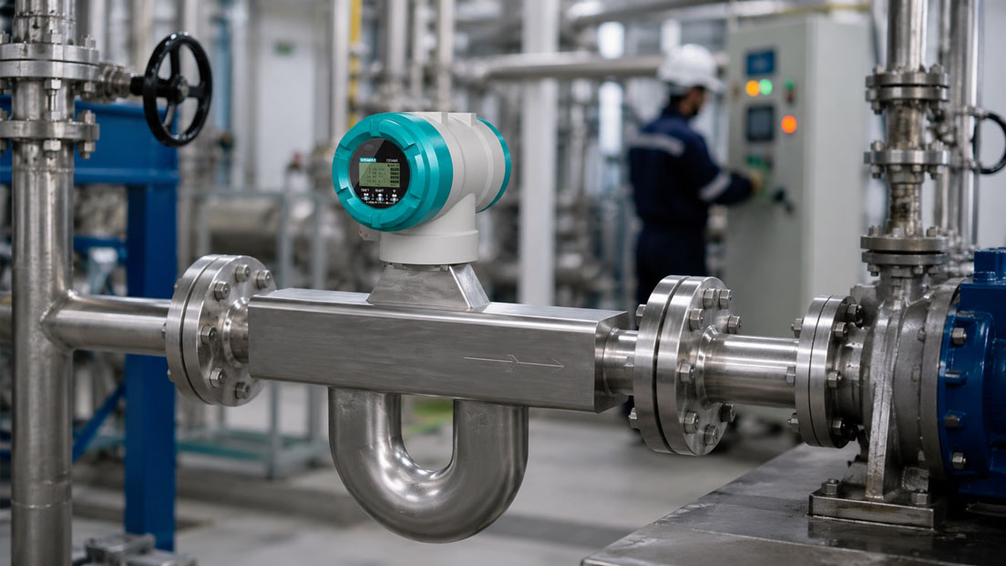
Coriolis flow meters are among the most accurate measuring instruments for mass flow, density and temperature. They are used in chemicals, pharmaceuticals, the food industry, oil and gas, dosing applications, test benches and demanding process plants. Precisely because the measuring principle is very accurate, unstable values, jumping displays or implausible density values are quickly noticed during operation.
However, if a Coriolis flow meter fluctuates, the cause is not automatically the device itself. Unstable measured values are often caused by gas bubbles in the medium, two-phase flow, cavitation, mechanical vibration, pipe stress, unsuitable support, incorrect installation, low flow, unsuitable damping, incorrect zero point adjustment or ignored diagnostic messages.
This article explains how typical causes of unstable Coriolis measured values can be narrowed down. The focus is on gas bubbles, two-phase flow, vibration, mechanical stress, installation situation, pipe support, zero point adjustment, low flow, damping, diagnostic functions, transmitter parameterization and assessment of the complete measurement chain.
Table of contents
- Basics: why Coriolis flow meters are very accurate but sensitive to process conditions
- Typical symptoms: how unstable measured values can be recognized
- Gas bubbles and two-phase flow as frequent causes
- Check cavitation, outgassing and pressure conditions
- Vibration and mechanical disturbances in the pipework
- Installation, pipe support and mechanical stress
- Zero point adjustment and low flow
- Damping, filters and transmitter parameterization
- Using diagnostic messages correctly
- Check output signal, PLC scaling and measurement chain
- Practical example: mass flow fluctuates after pump modification
- Which measuring instruments / products are suitable?
- Conclusion: always assess unstable Coriolis values together with process and installation conditions
- FAQ: frequently asked questions about unstable Coriolis flow meters
Basics: why Coriolis flow meters are very accurate but sensitive to process conditions
A Coriolis flow meter measures mass flow directly. To do this, one or more measuring tubes are excited into vibration. When medium flows through these tubes, the vibration behavior changes. From this change, the mass flow can be calculated. Depending on the device, additional variables such as density and temperature can also be measured.
The major advantage of this measuring principle is that a volume flow does not first have to be converted using density or temperature. Coriolis measures mass directly and is therefore particularly interesting for dosing, recipes, filling, balancing, process optimization and applications with changing density. At the same time, however, the measuring principle also means that process conditions and the mechanical installation situation play an important role.
For a Coriolis flow meter to work stably, the measuring tubes must be able to vibrate cleanly. Disturbances occur when the medium does not flow through the sensor as a single phase, when gas bubbles are present, when the flow is very low, when strong vibrations are introduced into the pipework or when the measuring device has been installed under mechanical stress. Pump pulsation, cavitation, poor venting or incorrect parameterization can also cause unstable values.
In practice, the question should therefore not only be whether the sensor “measures correctly”. What matters is whether medium, process condition, installation, pipework and transmitter parameters fit together. A high-quality Coriolis flow meter can only provide stable values if the process at the measuring point is sufficiently stable and measurable.
| Influencing variable | Why relevant? | Typical error pattern |
|---|---|---|
| Gas bubbles in the medium | Change density and vibration behavior of the measuring tubes | Mass flow and density jump or become unstable. |
| Two-phase flow | Liquid and gas do not flow homogeneously through the sensor | Measured value becomes unstable, diagnostics report poor signal quality. |
| Vibration | External vibrations can overlay the Coriolis signal | Display fluctuates despite a constant process. |
| Mechanical stress | Installation under stress influences tube vibration | Zero point shifts or measured value drifts. |
| Low flow | Signal is close to the lower measuring limit | Measured value appears noisy or jumps around the zero point. |
Typical symptoms: how unstable measured values can be recognized
Unstable Coriolis measured values do not always appear in the same way. Sometimes only the mass flow fluctuates while the density remains stable. In other cases, flow, density and temperature jump at the same time. In some plants, the problem only occurs during start-up, in others only at partial load, after a pump change, during a batch change or after maintenance work.
An important distinction is whether the fluctuation actually comes from the process or is only visible in the signal output. If the measured value on the device is stable but jumps in the PLC, the cause is more likely to be scaling, signal transmission, filtering or evaluation. If diagnostic messages, density fluctuations or poor signal quality are already shown at the transmitter, the cause is more often in the medium, installation or sensor environment.
The time profile also helps with troubleshooting. If the value fluctuates periodically with pump speed or compressor cycling, a mechanical or hydraulic cause is likely. If jumps occur after opening a valve, trapped air or cavitation may be present. If the problem only occurs at small quantities, the lower measuring range and the zero point should be considered.
Good diagnostics therefore start with a description of the error pattern: Which measured variable fluctuates? When does the fluctuation occur? Is it dependent on flow, pressure, temperature, pump, valve position or medium? Are there diagnostic messages? Was anything changed to the pipework, pump, parameterization or installation before the issue appeared?
Gas bubbles and two-phase flow as frequent causes
Gas bubbles are one of the most common causes of unstable Coriolis measured values. Coriolis devices can measure very accurately when the medium flows homogeneously through the sensor. However, if gas is present in a liquid, the vibration behavior of the measuring tubes changes. At the same time, the density can fluctuate strongly. The device then no longer detects a calm, reproducible measuring condition.
Gas bubbles can be created in different ways. A pipe has not been fully vented, a pump draws in air, a tank runs empty, the medium outgasses due to pressure drop or a valve creates locally unfavorable pressure conditions. Batch changes, cleaning processes, filling operations or high flow velocities can also bring gas fractions into the sensor.
Two-phase flow is particularly critical because liquid and gas are not evenly distributed. Gas pockets, bubble packages or changing mixed states can occur. The measured value then does not jump because the device measures “randomly”, but because the physical condition in the sensor is constantly changing.
To narrow down the cause, it should be checked whether the pipe is completely filled, whether venting points are available, whether the pump draws in air-free medium, whether pressure and temperature promote outgassing and whether the measuring device is located at a point where gas can accumulate. With liquids, an installation position that supports complete filling and avoids gas accumulation is often advantageous.
| Cause of gas fractions | Typical indication | Test approach |
|---|---|---|
| Pipe not fully vented | Fluctuations especially after start-up or maintenance | Check venting, filling condition and pipe routing. |
| Pump draws in air | Measured value fluctuates depending on suction condition | Check suction side, tank level, seals and suction conditions. |
| Outgassing due to pressure drop | Density value jumps with valve position or pressure change | Assess pressure conditions and vapor pressure of the medium. |
| Two-phase flow | Mass flow and density are simultaneously unstable | Stabilize process condition or change measuring point. |
| Tank runs empty | Instability at the end of a batch or dosing process | Check minimum level, suction position and shutdown logic. |
Check cavitation, outgassing and pressure conditions
Cavitation occurs when the local pressure in the medium drops so far that vapor bubbles form and then collapse again. In Coriolis flow meters, this can lead to strong disturbances because a homogeneous liquid is no longer flowing through the sensor. Cavitation also creates mechanical stress and can cause long-term damage to pumps, valves or pipework.
Outgassing is a related issue. Certain liquids contain dissolved gases that can be released when pressure drops, temperature changes or flow routing is unfavorable. Even if classic cavitation is not present, gas bubbles can form and make the Coriolis measurement unstable. This point should be considered especially with volatile media, solvents, hydrocarbons, water-based media with dissolved air or warm liquids.
The position of valves is important here. A throttling valve directly upstream of the measuring device can create pressure drop and turbulence. In many applications, it is better to install the Coriolis flow meter so that sufficient back pressure is present and critical pressure drops do not occur directly in the sensor. Pumps, filters, reducers and pipe restrictions can also influence local pressure conditions.
With unstable values, it should therefore be checked whether the plant has sufficient pressure reserve over the entire operating range. Minimum pressure, medium temperature, vapor pressure, pump curve, valve position and flow range should be considered together. If the measurement is unstable only at certain load points, this can indicate local outgassing or cavitation.
Vibration and mechanical disturbances in the pipework
Coriolis flow meters work with vibrating measuring tubes. The mechanical environment is therefore particularly important. External vibration, pump pulsation, poorly supported pipework or vibrating equipment can influence the measuring signal. Modern devices are designed to withstand many external influences, but an unfavorable installation situation can still promote unstable values.
Typical sources include piston pumps, dosing pumps, compressors, poorly aligned drives, vibrating machine foundations, flexible hose lines or long pipe sections that are not sufficiently supported. If the vibration is in an unfavorable frequency range, it can influence the measuring behavior more strongly than expected.
An indication of vibration is a measured value that fluctuates periodically although process pressure, valve position and medium appear stable. If several measuring instruments in the same pipe section show similar fluctuations, a mechanical or hydraulic cause may be present. Diagnostics should therefore not start only at the Coriolis device, but at the entire pipework.
Countermeasures can include improved pipe support, modified pipe routing, vibration decoupling, distance from pumps, pulsation dampers or a different measuring point. It is important not to stress the measuring device through rigid supports. Good installation supports the pipework without mechanically loading the sensor.
Installation, pipe support and mechanical stress
A Coriolis flow meter should be installed in the pipework free from mechanical stress. If flanges are not aligned properly, pipes are pulled into position when tightening bolts or the sensor is used as a mechanical compensation for pipe misalignment, unwanted stresses can occur. These stresses can influence zero point and measuring stability.
The weight of the measuring device also plays a role depending on nominal size. Larger Coriolis sensors are heavy and should not hang freely on the pipework if this creates bending moments. Conversely, the support must not act directly on the sensor in a way that affects the vibration of its measuring tubes. The manufacturer’s specifications for support are therefore particularly important.
With liquids, the installation position should be selected so that the sensor remains completely filled and gas bubbles do not remain in the measuring tube. Other requirements apply to gases. With media containing solids, viscous liquids or crystallizing substances, deposits, drainability, cleaning and temperature control must also be considered.
A common practical error is that after a pipe modification everything is mechanically tight, but the measurement becomes unstable. In that case, the support may have been changed, a pump moved closer to the sensor, a valve repositioned or a reducer added. Such changes should always be queried during troubleshooting.
| Installation point | Why important? | Possible consequence of error |
|---|---|---|
| Stress-free installation | Measuring tubes should vibrate freely and reproducibly | Zero point shift, drift or unstable values. |
| Pipe support | Reduces mechanical load and vibration | Vibrations or bending moments influence the measurement. |
| Installation position | Supports complete filling and venting | Gas bubbles remain in the sensor or pipe partially runs empty. |
| Distance from pumps and valves | Reduces pulsation, pressure jumps and outgassing | Measured value fluctuates depending on pump or valve condition. |
| Process connections | Must be tight, suitable and mechanically aligned cleanly | Stress, leakage or maintenance problems. |
Zero point adjustment and low flow
The zero point is an important parameter in Coriolis flow meters. When no flow is present, the device should not display any mass flow. In practice, however, the zero point depends on installation, medium, temperature, pressure, mechanical condition and process calmness. An incorrect zero point adjustment, or one carried out under unfavorable conditions, can later lead to unstable or shifted measured values.
A zero point adjustment should only be performed when the plant is in a suitable condition for it. The measuring tube must be completely filled, the medium should be at rest, no gas bubbles may move through the sensor, valves must close tightly and process conditions should be stable. If slight flow, pump pulsation or two-phase fractions are still present during the zero point adjustment, an incorrect zero point is learned.
An unstable zero point has a stronger effect especially at very small flows. If the application permanently operates near the lower measuring range, small zero point deviations can appear relatively large. The measured value then appears noisy or jumps around the zero point, although the plant may only be conveying very small quantities.
Before a new zero point adjustment is performed, it should always be checked whether the cause really lies in the zero point. If gas bubbles, cavitation, vibration or mechanical stress are present, a new adjustment will not solve the underlying problem. It can even make the situation worse if adjustment is carried out under unstable conditions.
Damping, filters and transmitter parameterization
Transmitters often offer options for damping or filtering the output signal. Higher damping can smooth short-term fluctuations and make the display steadier. This can be useful if the process actually fluctuates slightly, but a stable average value is required. However, damping must not be used as a substitute for technical troubleshooting.
If gas bubbles, cavitation or strong vibration are present, excessive damping merely hides the symptom. The measured value appears steadier, but the cause remains. In dosing processes or fast control loops, too much damping can also cause the system to respond too slowly. A seemingly stable value is then achieved at the cost of poor control quality.
Conversely, damping that is too low can make normal process fluctuations unnecessarily visible. Especially with pulsating pumps, fast valve movements or batch processes, it must be decided whether the instantaneous flow or a smoothed process value is required. This decision depends on the application, control system and documentation requirement.
Parameterization also includes measuring range, output signal, density output, low-flow cut-off, alarm behavior, diagnostic output and communication interface. A Coriolis system consists of sensor and transmitter. Both must match the application and the control system.
Using diagnostic messages correctly
Modern Coriolis transmitters provide not only measured values, but also diagnostic information. This can give indications of signal quality, tube vibration, density plausibility, empty pipe, two-phase flow, sensor fault, electronics fault or process instability. Such messages should always be evaluated when values are unstable.
A common mistake is to look only at the 4–20 mA signal or the display in the PLC. If the transmitter simultaneously outputs diagnostic warnings, the cause can be narrowed down much faster. Poor signal quality is more likely to indicate process or installation problems. A communication or output warning, on the other hand, points more toward the electrical measurement chain.
However, diagnostic messages must be interpreted correctly. A message about unstable density does not automatically mean that the density sensor is defective. It can also indicate gas bubbles, two-phase flow or changing medium composition. An empty pipe warning can be caused by actual partial filling, gas fractions or an unfavorable installation position.
For troubleshooting, it is helpful to consider diagnostic messages together with process data. Flow, pressure, temperature, pump condition, valve position, tank level and batch phase should be compared over time with the messages. This makes it possible to identify whether the instability is related to a particular process condition.
| Diagnostic indication | Possible cause | Practical assessment |
|---|---|---|
| Poor signal quality | Gas bubbles, vibration, mechanical disturbance | Check process and installation, not only output signal. |
| Density value unstable | Two-phase flow, gas fraction, changing medium composition | Compare density trend with pressure, temperature and process phase. |
| Empty pipe or partial filling indication | Incomplete filling, gas pockets, unfavorable installation position | Check pipe routing, venting and filling condition. |
| Output or communication error | Wiring, supply, parameterization, PLC scaling | Check electrical measurement chain separately. |
| Zero point warning | Incorrect adjustment, residual flow, mechanical stress | Check zero point again only under stable conditions. |
Check output signal, PLC scaling and measurement chain
Not every unstable display originates from the sensor. Sometimes the measured value in the Coriolis transmitter is stable, but the PLC, display or data recording shows jumps. In this case, the electrical measurement chain should be checked: output signal, supply, shielding, grounding, scaling, limit values, damping in the PLC and signal processing.
With a 4–20 mA output, it must be clear which measured variable is being output. Depending on parameterization, the signal can represent mass flow, volume flow, density, temperature or another variable. If the PLC expects a different unit or a different measuring range, an electrically correct signal can appear as an incorrect process value.
The UPS4E loop calibrator is suitable for testing 4–20 mA signals. It can be used to measure and simulate mA signals, test current loops and detect scaling errors between Coriolis transmitter, PLC, display or data logger. This test is particularly helpful after device replacement, parameter changes or control system modifications.
Digital communication should also be considered. With HART, Modbus, Profibus, Profinet or other interfaces, data point assignment, unit, update rate or diagnostic bits can play a role. An unstable display in the control system can be caused by incorrect data processing even though the sensor works plausibly at the transmitter.
Practical example: mass flow fluctuates after pump modification
In a chemical plant, a Coriolis flow meter is used for dosing a liquid. Before modification, the measurement works stably. After replacing the pump, however, the mass flow shows significant fluctuations. The PLC display jumps, and an unstable density is occasionally displayed. At first, it is assumed that the Coriolis sensor is defective.
During the first check, the 4–20 mA signal is inspected. The signal follows the fluctuations but is electrically plausible. The scaling in the PLC is correct. Diagnostic indications of unstable signal quality are visible at the transmitter. This shifts troubleshooting from the output signal to the process and installation situation.
Process analysis shows that under certain operating conditions, the new pump draws in air on the suction side. In addition, a throttling valve was placed closer to the Coriolis flow meter. This causes pressure fluctuations and temporary gas bubbles in the medium at partial load. The sensor is therefore not showing a device fault, but an unstable process condition.
After adjusting the suction conditions, improving venting and changing the valve position, the measurement stabilizes again. A new zero point adjustment is only performed after the pipe is completely filled and the process is calm. The example shows: Coriolis fault diagnostics should always consider medium, pump, pipework, installation and signal together.
Which measuring instruments / products are suitable?
For demanding Coriolis applications, the SITRANS FCS600 robust Coriolis flow sensor is a suitable solution. It is designed for extreme conditions and corrosive liquids and, depending on the version, is suitable for demanding media, wide temperature ranges and industrial process applications. Especially with difficult media, clean sizing is crucial so that measuring range, material, pressure, temperature and installation situation fit together.
The SITRANS FCT040 transmitter is an advanced transmitter for Coriolis flow meters of the SITRANS FC series. It is particularly relevant when diagnostics, parameterization, output signals, communication and usability are to be considered in addition to the sensor. With unstable measured values, the transmitter is an important starting point for diagnostic messages and signal testing.
The category Coriolis / Vortex is the right starting point when Coriolis and vortex flow meters are to be compared or sized for an application. Coriolis is particularly strong in direct mass flow measurement, density information and high accuracy. Vortex, on the other hand, is often interesting for steam, gases and robust volumetric flow applications.
If a Coriolis transmitter is integrated into a PLC or control system via 4–20 mA, the UPS4E loop calibrator is a helpful tool for commissioning, troubleshooting and signal testing. It makes it possible to quickly determine whether an unstable display originates from the process, the transmitter or the electrical measurement chain.
| Product / area | Typical use | Particularly relevant for |
|---|---|---|
| SITRANS FCS600 Coriolis flow sensor | Robust Coriolis measurement with demanding media and process conditions | Corrosive liquids, extreme temperatures, industrial applications and direct mass flow measurement |
| SITRANS FCT040 transmitter | Transmitter for SITRANS FC Coriolis systems | Parameterization, diagnostics, output signals, communication and measured value assessment |
| Coriolis / Vortex | Selection of Coriolis and vortex flow meters | Principle comparison, process sizing, liquids, gases, steam and mass flow |
| Pipe support and installation accessories | Mechanically stable and stress-free installation | Vibration, mechanical stress, heavy sensors and demanding pipework |
| UPS4E loop calibrator | Testing and simulation of 4–20 mA signals | PLC scaling, output signal testing, commissioning and troubleshooting on analog signals |
Conclusion: always assess unstable Coriolis values together with process and installation conditions
An unstable Coriolis flow meter is not automatically defective. Often, the device shows very accurately that the process at the measuring point is not stable. Gas bubbles, two-phase flow, cavitation, vibration, mechanical stress, unfavorable pipe support, incorrect zero point adjustment or low flow can significantly influence the measurement.
Troubleshooting should therefore be systematic. First, it must be clarified which measured variable fluctuates and when the problem occurs. Then medium, filling condition, gas fractions, pressure conditions, pump, valves, installation position, pipe support, zero point and diagnostic messages are checked. Only then should device replacement or major interventions be considered.
The most important recommendation is: always consider Coriolis measurement as a complete system. Sensor, transmitter, medium, pipework, mechanical installation, process condition and output signal must fit together. Anyone who takes these relationships into account will find the cause of unstable values much faster and avoid unnecessary device replacement.
FAQ: frequently asked questions about unstable Coriolis flow meters
Why does a Coriolis flow meter show unstable values?
Common causes are gas bubbles, two-phase flow, cavitation, vibration, mechanical stress, low flow, incorrect zero point adjustment or unsuitable parameterization. The electrical measurement chain can also cause an unstable display.
Are gas bubbles critical in Coriolis measurements?
Yes. Gas bubbles change the density and vibration behavior of the measuring tubes. As a result, mass flow and density can fluctuate or diagnostic messages about signal quality can occur.
What does two-phase flow mean?
Two-phase flow means that two phases flow through the pipe at the same time, for example liquid and gas. Coriolis devices require flow conditions that are as homogeneous as possible for the measurement to remain stable.
Can cavitation influence the measured value?
Yes. Cavitation creates vapor bubbles and strong local disturbances. This can make the Coriolis measurement unstable and also cause mechanical stress in the pump, valve or pipework.
Why does the density value also fluctuate?
A fluctuating density value is often an indication of gas fractions, two-phase flow, changing medium composition or unstable process conditions. It should be considered together with pressure, temperature and flow.
Can vibration disturb a Coriolis flow meter?
Yes. Because Coriolis devices work with vibrating measuring tubes, external vibrations, pump pulsations or poorly supported pipework can influence the measuring signal.
How can a mechanical cause be recognized?
Mechanical causes often appear as periodic fluctuations, dependence on pump speed or changes after pipework modifications. Visible pipe vibration or insufficient support are also indications.
Why is stress-free installation important?
Mechanical stress can influence the vibration of the measuring tubes and lead to zero point shift, drift or unstable measured values. The sensor should not be used as compensation for pipe misalignment.
When should zero point adjustment be performed?
Zero point adjustment should only be performed when the measuring tube is completely filled, no flow is present, no gas bubbles move through the sensor and process conditions are stable.
Can an incorrect zero point adjustment make the measurement worse?
Yes. If residual flow, gas bubbles, vibration or unstable conditions are present during adjustment, an incorrect zero point can be stored. This causes problems especially at small flows.
Why are low flows problematic?
At very small flows, the useful signal is close to the zero point. Small disturbances, zero point deviations or process fluctuations then have a relatively stronger effect and can make the measured value appear unstable.
Does more damping help against unstable values?
Damping can smooth the display, but it does not eliminate the cause. With gas bubbles, cavitation or vibration, high damping only hides the symptom. In fast dosing or control processes, too much damping can be disadvantageous.
Which diagnostic messages are important?
Important indications include signal quality, density instability, empty pipe, partial filling, zero point, sensor condition, output error or communication error. These messages should be assessed together with process data.
Can the PLC cause an unstable display?
Yes. Incorrect scaling, wrong unit, unsuitable filtering, signal interference or incorrect data point assignment can make the display appear unstable even though the transmitter is working plausibly.
How do you test a 4–20 mA output signal?
A loop calibrator can be used to measure or simulate the mA signal. This makes it possible to check whether transmitter, PLC, display or data logger use the same measuring range and the same measured variable.
When should the sensor be replaced?
Replacement should only be considered after systematic checking of process, medium, gas fractions, pressure, vibration, installation, zero point, diagnostic messages and output signal. Many instabilities originate outside the sensor.
Which devices are suitable for demanding Coriolis applications?
For robust Coriolis applications, sensors such as the SITRANS FCS600 in combination with a suitable transmitter such as the SITRANS FCT040 are suitable. Precise sizing for medium, measuring range, pressure, temperature and installation situation is decisive.