


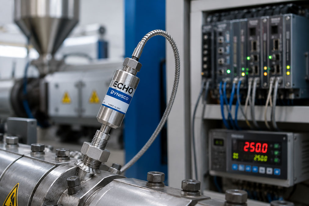
Melt pressure sensors and melt pressure transmitters are used in extrusion lines, injection molding machines, compounding systems, recycling processes, hot runner systems and polymer processing plants. They measure the pressure of the plastic melt or a comparable process medium directly at critical points such as screw outlet, filter, screen changer, nozzle, mold or hot runner. This directly affects process safety, quality, system availability and reproducibility.
However, selecting a melt pressure sensor is not only about pressure range, thread, diaphragm, filling medium, temperature range or accuracy. The output signal is just as important. In practice, users often have to decide whether a classic sensor with an mV/V signal or a melt pressure transmitter with a 4–20 mA output is better suited to the system. Voltage outputs such as 0–10 V or 0–5 V may also be suitable depending on the display, controller or control system.
This article explains the differences between mV/V, 4–20 mA and voltage signals for melt pressure sensors. The focus is on external amplifiers, integrated transmitters, display instruments, controllers, PLC inputs, cable length, noise immunity, calibration, shunt calibration, signal testing and the question of which output signal is the better choice for which application.
Table of contents
- Basics: why the output signal is so important
- mV/V signal: classic sensor with strain gauge bridge
- External amplifier, display or controller for mV/V sensors
- 4–20 mA: melt pressure transmitter with integrated signal amplifier
- 0–10 V and 0–5 V: voltage signals as an alternative
- mV/V or 4–20 mA: direct comparison
- Cable length, noise immunity and machine environment
- Display, controller or PLC: the output signal must match the input
- Calibration, shunt calibration and signal testing
- Replacing a sensor: why the output signal cannot simply be changed
- Practical example: extruder with old mV/V sensor is expanded for PLC connection
- Which measuring instruments / products are suitable?
- Conclusion: the right output signal determines safe integration
- FAQ: frequently asked questions about melt pressure sensors with mV/V or 4–20 mA
Basics: why the output signal is so important
A melt pressure sensor detects the process pressure at a point where high temperatures, high pressures, mechanical loads and demanding media conditions can occur. The actual sensor converts the mechanical pressure load into an electrical signal. This signal must then be evaluated by a display, controller, amplifier, data logger or PLC.
This is exactly where many selection and replacement errors occur. A sensor with an mV/V output cannot be connected directly to just any PLC analog input without suitable excitation voltage and amplification. A 4–20 mA transmitter, on the other hand, requires a suitable current loop and correct scaling in the input module. A voltage output such as 0–10 V fits certain controllers well, but is not always the best solution for long cable runs and electrically noisy environments.
The output signal therefore determines which electronics are required, how immune the transmission is to interference, how easy commissioning is and how well the sensor can be integrated into an existing machine. In new systems, the signal can be selected to match the control concept. In existing systems, however, the installed display or control device often has to be taken into account.
For this reason, signal selection should always be considered together with the complete measurement chain. This includes sensor, connection cable, connector, excitation voltage, amplifier, display, controller, PLC input, scaling, calibration and documentation. A technically high-quality sensor only delivers reliable values if its output signal matches the connected electronics.
| Output signal | Typical meaning | Typical use |
|---|---|---|
| mV/V | Unamplified sensor signal, dependent on excitation voltage | Display instruments, controllers or amplifiers with strain gauge input |
| 4–20 mA | Standardized current signal from a transmitter | PLC, control system, long cables, industrial process signals |
| 0–10 V | Standardized voltage signal | Controllers, data loggers, short cables, simple analog inputs |
| 0–5 V | Voltage output with a smaller range | Specific machine controls or older evaluation devices |
| Digital / fieldbus | Digital measured values and diagnostic data | Modern automation, diagnostics and process data acquisition |
mV/V signal: classic sensor with strain gauge bridge
The mV/V signal is a classic sensor signal for melt pressure transducers. It is often generated by sensors with a strain gauge bridge. The specification mV/V means that the output signal is given in millivolts per volt of excitation voltage. A sensor with 3.33 mV/V, for example, delivers a small millivolt signal at full span, and the magnitude of this signal depends on the applied bridge excitation.
This signal is very close to the actual sensing element. It does not yet contain strong signal conditioning inside the sensor itself. As a result, an mV/V sensor depends on suitable external electronics. These electronics supply the measuring bridge with a stable excitation voltage, amplify the small signal, perform the scaling and provide the measured value for display or control.
The advantage of an mV/V sensor lies in the classic, direct sensor technology. Many older extruders, injection molding machines and controllers were designed precisely for this type of sensor signal. If an existing controller has an mV/V input, a compatible mV/V melt pressure sensor can be a very good and simple replacement solution.
The disadvantage is that the small signal is more sensitive to interference, cable quality, connectors and incorrect evaluation electronics. The complete measurement chain must be set up cleanly. Excitation voltage, bridge resistance, cable, shielding, amplifier input and calibration must match. An mV/V sensor is therefore not automatically the best choice when the measured value has to be transmitted directly to a PLC over longer distances.
External amplifier, display or controller for mV/V sensors
With an mV/V output, the external electronics are a central part of the measurement chain. A display instrument, melt pressure controller or measuring amplifier performs several tasks at the same time. It provides the bridge excitation voltage, evaluates the sensor signal, scales the pressure range and provides the measured value as a display, relay contact, control signal or analog output signal.
This structure has been proven for many years in many plastics machines. The sensor is installed in the process, the connection cable runs to the controller or display instrument, and the pressure value, limit value, alarm or control function is processed there. For machines with existing Dynisco displays or pressure controllers, an mV/V sensor can therefore be very suitable if compatibility has been clearly verified.
However, it is important to note that not every mV/V sensor fits every controller. Pressure range, output sensitivity, bridge resistance, excitation voltage, pin assignment, connector type, shunt calibration and temperature compensation must be checked. Even small differences can mean that a sensor fits mechanically but delivers incorrect electrical values.
During modernization, the external electronics can also serve as an interface to the PLC. In this case, an mV/V sensor continues to be evaluated by the measuring amplifier, and the amplifier outputs a standardized signal such as 4–20 mA or 0–10 V to the control system. This can be useful if a proven sensor type is to be retained while the system also needs digital process data or PLC integration.
| Component | Task with mV/V sensors | What to pay attention to? |
|---|---|---|
| Bridge excitation | Supplies the strain gauge bridge in the sensor | Voltage must match sensor and evaluation device. |
| Measuring amplifier | Amplifies the small millivolt signal | Input sensitivity and scaling must be correct. |
| Display instrument | Displays the pressure value locally or in the control cabinet | Pressure range, unit and zero point must be set. |
| Controller | Uses the pressure value for control or limit values | Control parameters, alarm limits and sensor type must match. |
| Connection cable | Transmits excitation, signal and shunt line | Check shielding, pin assignment, length and connector. |
4–20 mA: melt pressure transmitter with integrated signal amplifier
A melt pressure transmitter with a 4–20 mA output already contains integrated signal conditioning. The sensor not only converts the process pressure into a raw signal, but outputs a standardized current signal. In most cases, 4 mA corresponds to the lower end of the measuring range and 20 mA to the upper end. The signal is then evaluated directly via an analog input, display, data logger or PLC.
The most important advantage is robust signal transmission. Current signals are proven in industrial environments and are well suited for longer cable runs. Interference, voltage drops or contact resistance are often less critical with a current signal than with small mV/V signals or voltage outputs. In addition, wire break or fault conditions can often be detected more easily because the signal may move outside the normal 4–20 mA range.
A 4–20 mA transmitter is particularly useful when the melt pressure is to be connected directly to a PLC, control system or remote I/O. For modern systems, retrofit projects and process data acquisition, this is often the simpler solution. The control system receives a standardized signal that can be scaled and processed in pressure units.
However, the entire measurement chain must also be correctly designed for 4–20 mA. Supply voltage, load, two-wire or three-wire connection, shielding, scaling, fault current, measuring range and evaluation in the PLC input must all match. A 4–20 mA sensor is not automatically integrated correctly just because it provides a standard output signal.
0–10 V and 0–5 V: voltage signals as an alternative
In addition to mV/V and 4–20 mA, there are melt pressure sensors and transmitters with voltage outputs, for example 0–10 V, 0–5 V or comparable ranges. These signals are often used by controllers, data loggers or specific machine control systems. They are easy to understand, directly measurable and available in many automation environments.
Voltage outputs can be particularly useful when the cable length is short, the electrical environment is clean and the connected input is designed exactly for this signal. When mounted close to the evaluation electronics in the control cabinet, 0–10 V signals can work well. Older systems or certain controller concepts also use voltage signals as a standard interface.
The disadvantage is greater sensitivity to voltage drops, reference potentials and electromagnetic interference. With longer cables, machines with frequency converters, heating power, motors or unclear grounding, a current signal may be advantageous. Reference potentials must also be considered carefully so that no measured value shifts occur.
Voltage outputs are therefore not a bad solution, but they should be selected consciously. The decisive factors are whether the input of the control system or display is designed for the signal, how long the cable is and how much electrical noise is present in the environment. If robust process signal transmission over longer distances is required, 4–20 mA is often the more stable choice.
mV/V or 4–20 mA: direct comparison
The decision between mV/V and 4–20 mA is essentially a decision between a classic raw signal with external evaluation and a standardized transmitter signal with integrated signal conditioning. Both variants have their place. The right choice depends on which electronics are available, how the system is built and what requirements exist for signal transmission and maintenance.
mV/V is suitable when an existing controller, amplifier or display is specifically designed for melt pressure sensors with a strain gauge bridge signal. This is the case in many existing plastics machines. The evaluation electronics then handle excitation, amplification, shunt calibration, display and sometimes control. The sensor itself remains comparatively simple in terms of signal technology.
4–20 mA is suitable when the measured value is to be transmitted directly to a PLC, control system or modern process data acquisition system. The sensor or transmitter already provides a standardized signal. This reduces the need for special strain gauge evaluation electronics and makes integration into general automation systems easier.
The decision should not be based only on price or availability. When replacing a sensor, the new signal must match the existing electronics. In a new system, the signal should be selected according to control concept, cable length, interference environment, diagnostic requirements and maintenance concept.
| Criterion | mV/V sensor | 4–20 mA transmitter |
|---|---|---|
| Signal type | Small raw signal from the measuring bridge | Standardized industrial current signal |
| Evaluation electronics | External amplifier or controller required | Can be connected directly to a suitable analog input |
| Cable length | More sensitive, clean shielding is important | Well suited for longer cables |
| Existing systems | Good with existing mV/V controllers | Good for PLC modernization or control system integration |
| Calibration | Shunt calibration and amplifier adjustment are important | mA scaling and loop testing are important |
Cable length, noise immunity and machine environment
Plastics machines are electrically demanding environments. Heating bands, motors, frequency converters, servo drives, contactors, controllers, power electronics and long cable runs can cause interference. The noise immunity of the output signal is therefore an important selection criterion.
An mV/V signal is small and should be routed carefully. Shielding, clean grounding, suitable cables, correct connectors and sufficient distance from power cables are important. If the signal is routed over longer distances or through electrically noisy areas, measured value quality may suffer. This does not mean that mV/V is unsuitable, but the installation must be done carefully.
A 4–20 mA signal is more robust against many typical interference influences. Since the measured value is transmitted as a current, cable resistances within the permissible load are less critical. A current signal is also very common in industrial PLC and control systems. This can be a clear advantage with long cable runs from the extruder to the control cabinet.
Nevertheless, 4–20 mA also requires clean installation. Shielding, equipotential bonding, supply, load, cable routing and EMC-compliant wiring remain important. If the signal fluctuates, not only the sensor should be examined, but also the cable, input module, power supply and scaling in the control system.
Display, controller or PLC: the output signal must match the input
The most important practical question is: What will the melt pressure sensor be connected to? An existing Dynisco controller or a special display instrument may be designed for mV/V sensors. A PLC, on the other hand, usually has standard analog inputs for 4–20 mA or 0–10 V. Directly connecting an mV/V sensor to a normal PLC input is generally not useful because the signal is too small and excitation as well as amplification are missing.
For display instruments, it must be checked which sensor type is supported. Some displays can directly evaluate mV/V signals and offer shunt calibration, limit relays or analog output. Other displays expect an existing 4–20 mA or 0–10 V signal. For controllers, it is also relevant whether the pressure value is only displayed or actively used for process control.
In PLC applications, scaling is decisive. A 4–20 mA input must know which pressure corresponds to 4 mA and which pressure corresponds to 20 mA. If a 0–700 bar transmitter is scaled in the PLC as 0–500 bar, all measured values are incorrect even though the electrical signal is correct. Unit, filter, limit values and alarm behavior must also be correct.
For this reason, the output signal should always be coordinated with the planned evaluation. Sensor, display, controller and PLC are not separate decisions. They form one measurement chain. The more clearly this measurement chain is defined, the fewer problems occur during commissioning, replacement and troubleshooting.
| Evaluation device | Suitable signal | Important check |
|---|---|---|
| Melt pressure controller with strain gauge input | mV/V | Check sensitivity, excitation, shunt and pin assignment. |
| Digital display for process signals | Depending on version mV/V, 4–20 mA or 0–10 V | Clearly define input type and scaling. |
| PLC analog input | Usually 4–20 mA or 0–10 V | Parameterize measuring range, unit, filter and fault behavior. |
| Data logger | Often 4–20 mA or voltage signal | Check sampling rate, scaling and signal source. |
| Control system | Standardized analog or digital signal | Document data point, unit, limit values and alarm handling. |
Calibration, shunt calibration and signal testing
Melt pressure sensors must not only be selected correctly, but also tested and calibrated correctly. With mV/V sensors, shunt calibration plays an important role. A defined electrical resistor is used to generate a test signal that corresponds to a specific percentage of the measuring span. This allows the evaluation electronics to be checked without mechanically applying pressure to the sensor.
Shunt calibration is particularly helpful for basically checking sensor, cable and amplifier. However, it does not replace full pressure calibration under defined conditions. If a process value is implausible, the shunt test can show whether the electrical measurement chain responds. But on its own, it does not indicate whether the diaphragm, pressure transmission, mounting bore or process conditions are correct.
With 4–20 mA transmitters, the focus is more on signal and loop testing. It must be checked whether 4 mA and 20 mA correctly match the pressure range, whether the current loop operates stably and whether the PLC scales the values correctly. After replacing a device, it is particularly important to compare pressure range and output signal with the control system.
The UPS4E loop calibrator is suitable for testing 4–20 mA signals. It can be used to measure and simulate mA signals, test current loops and detect scaling errors between melt pressure transmitter, display, PLC or data logger. Especially during commissioning, modification or troubleshooting, this quickly helps determine whether the fault is in the sensor, the cable or the evaluation.
Replacing a sensor: why the output signal cannot simply be changed
When replacing a melt pressure sensor, attention is often first paid to pressure range, process connection and diaphragm. This is important, but not sufficient. The output signal must also match exactly. An mV/V sensor cannot simply be replaced by a 4–20 mA transmitter if the existing controller expects a strain gauge bridge input. Conversely, a 4–20 mA input cannot correctly evaluate an unamplified mV/V bridge.
The pin assignment is also critical. Even if connector and thread look similar, pin assignment, excitation, shunt line, signal wires or shielding can be different. Incorrect wiring can cause measurement errors or damage sensor and electronics. Type plate, datasheet and existing wiring should therefore always be compared carefully.
In a retrofit, changing the signal can be useful, but it must be planned. If an old mV/V measurement chain is to be replaced by a PLC-based solution, a 4–20 mA transmitter may be the more modern choice. However, analog input, supply, scaling, alarm limits, documentation and, if necessary, mechanical installation situation must then be adapted.
For spare parts in existing machines, the safest solution is often to keep the previous signal, provided the evaluation electronics remain unchanged. If the controller or control system is modernized at the same time, the output signal should be reassessed. This helps avoid unnecessary adapter solutions and later troubleshooting.
Practical example: extruder with old mV/V sensor is expanded for PLC connection
A melt pressure sensor with mV/V output is installed in an extrusion line. The sensor is connected to an older pressure controller that displays the value locally and processes limit values. The system is basically running stably. As part of a modernization project, the operator wants to additionally record melt pressure in the PLC and use it for trend logging.
The first idea is to connect the sensor directly to a free analog input of the PLC. However, this does not work because the PLC input is designed for 4–20 mA and cannot evaluate an mV/V sensor signal. Bridge excitation, amplification and shunt function are also missing. The sensor is therefore not wrong, but it does not connect directly to the new evaluation system.
There are several sensible options. The existing mV/V sensor can continue to be evaluated via a suitable amplifier or controller that additionally provides a 4–20 mA signal to the PLC. Alternatively, if a sensor replacement is planned, a melt pressure transmitter with integrated 4–20 mA output can be selected. The PLC must then be scaled accordingly, and the existing controller function may need to be replaced or adapted.
The example shows: signal selection is not purely a sensor question. It determines how display, controller, PLC and documentation are connected. Anyone who considers the complete measurement chain before the modification avoids incorrect orders and time-consuming troubleshooting during commissioning.
Which measuring instruments / products are suitable?
The category Dynisco melt pressure sensors is the right starting point when melt pressure is to be measured directly in the process and different output signals such as mV/V, 4–20 mA, 0–5 V or 0–10 V need to be considered. The decisive factor is not only the pressure range, but the complete match with medium, temperature, process connection and evaluation electronics.
The category melt pressure transmitters is particularly relevant when a standardized signal is required for PLC, display, data logger or control system. Transmitters with 4–20 mA or voltage output simplify integration into modern automation systems and can offer advantages with longer cables or electrically noisy environments.
For applications in plastics and polymer processing, it is also worth looking at Dynisco products as a whole. In addition to melt pressure sensors and melt pressure transmitters, these also include sensors for injection molding, melt temperature sensors, display and control devices, sensor accessories and calibration or test equipment for the measurement chain.
If 4–20 mA signals need to be checked, simulated or compared with a PLC during commissioning, the UPS4E loop calibrator is a helpful tool. It quickly shows whether a melt pressure transmitter outputs correctly, whether the analog input is scaled correctly and whether the current loop operates stably.
| Product / area | Typical use | Particularly relevant for |
|---|---|---|
| Dynisco melt pressure sensors | Melt pressure measurement in extrusion, injection molding and plastics processing | mV/V, 4–20 mA, voltage signals, high temperatures and high pressures |
| Melt pressure transmitters | Melt pressure measurement with standardized output signal | PLC connection, control system, data logger, retrofit and longer cable runs |
| Display and control devices | Evaluation, display and control of melt pressure signals | mV/V sensors, limit values, shunt calibration and machine control |
| Measuring amplifier / signal converter | Conversion of small sensor signals into standard signals | mV/V to 4–20 mA or 0–10 V, modernization and PLC connection |
| UPS4E loop calibrator | Testing and simulation of 4–20 mA signals | Commissioning, troubleshooting, scaling checks and signal comparison |
Conclusion: the right output signal determines safe integration
Whether a melt pressure sensor with mV/V or a melt pressure transmitter with 4–20 mA is better suited depends primarily on the existing or planned evaluation electronics. mV/V is ideal when a suitable controller, amplifier or display with strain gauge input is available. 4–20 mA is particularly useful when the measured value is to be transmitted robustly and in standardized form to a PLC, control system or data logger.
In existing systems, the installed setup should be checked carefully. Output signal, excitation, pin assignment, shunt calibration, pressure range and scaling must match the existing controller or control system. A mechanically compatible sensor is not a complete solution if the electrical signal is not compatible.
The most important recommendation is: always consider melt pressure sensor, connection cable, display, controller, amplifier and PLC as a complete measurement chain. Selecting the right output signal early helps avoid incorrect orders, unstable measured values and unnecessary commissioning problems.
FAQ: frequently asked questions about melt pressure sensors with mV/V or 4–20 mA
What does mV/V mean for a melt pressure sensor?
mV/V means millivolts per volt of excitation voltage. The output signal depends on the bridge excitation and is a small raw signal from the measuring bridge. It requires suitable evaluation electronics with excitation and amplification.
What is the difference between a melt pressure sensor and a melt pressure transmitter?
A melt pressure sensor often provides an unamplified sensor signal, for example mV/V. A melt pressure transmitter has integrated signal conditioning and outputs a standardized signal such as 4–20 mA or 0–10 V.
When is mV/V the right choice?
mV/V is useful when an existing controller, display or measuring amplifier is designed specifically for this sensor signal. This is the case in many classic extrusion and injection molding machines.
When is 4–20 mA better?
4–20 mA is often better when the pressure value is to be transmitted directly to a PLC, control system or data logger. The signal is robust and very common for industrial analog inputs.
Can I connect an mV/V sensor directly to a PLC?
Usually not to a standard analog input. An mV/V signal is very small and requires bridge excitation and amplification. For a PLC, a measuring amplifier or transmitter output is usually required.
Can a 4–20 mA transmitter replace an mV/V sensor?
Only if the evaluation electronics also match. An existing controller with mV/V input cannot process a 4–20 mA signal without further adaptation. In a retrofit, the complete measurement chain must be adapted.
Which is more immune to interference: mV/V or 4–20 mA?
For longer cables and industrial environments, 4–20 mA is usually more immune to interference. mV/V can work very well, but requires particularly clean wiring, suitable shielding and suitable evaluation electronics.
What role does cable length play?
With mV/V signals, long cables and interference can be problematic because the signal is very small. 4–20 mA is better suited for longer signal paths as long as supply voltage and load are suitable.
What does shunt calibration mean?
During shunt calibration, a defined resistor is connected to generate a test signal. This allows the electrical measurement chain of an mV/V sensor to be checked without applying real pressure.
Does shunt calibration replace pressure calibration?
No. Shunt calibration primarily checks the electrical response of the measurement chain. Full pressure calibration evaluates the sensor under defined pressure and remains necessary for precise metrological statements.
What has to be scaled with 4–20 mA?
It must be defined which pressure value corresponds to 4 mA and which pressure value corresponds to 20 mA. This scaling must match in the transmitter, display and PLC or control system.
What happens if scaling is incorrect?
The electrical signal may be correct, but the displayed pressure value can still be wrong. Typical causes are incorrect units, incorrect pressure ranges or reversed lower and upper range values.
When is a 0–10 V output useful?
0–10 V can be useful if the connected input is designed for it, the cable is short and the environment is not heavily affected by electrical interference. For long industrial cables, 4–20 mA is often more robust.
Which information is required for selection?
Required information includes pressure range, process connection, diaphragm material, filling medium, temperature range, output signal, pin assignment, cable length, evaluation device and desired integration into controller or PLC.
Why is the pin assignment so important?
Depending on the signal type, melt pressure sensors can use different wires for excitation, signal, shunt and shielding. Incorrect wiring can lead to measurement errors or damage electronics.
How do you test a 4–20 mA signal?
A loop calibrator can be used to measure or simulate the signal. This makes it possible to check whether transmitter, cable, display and PLC process the same measuring range correctly.
What is particularly important when replacing a sensor?
In addition to thread, pressure range and diaphragm, output signal, excitation, pin assignment, shunt function, cable and scaling must be checked. Only then is the replacement sensor truly compatible.
Which products are suitable for melt pressure applications?
Dynisco melt pressure sensors and melt pressure transmitters are suitable for melt pressure applications. The selection depends on pressure range, temperature, medium, process connection, output signal and existing evaluation electronics.