


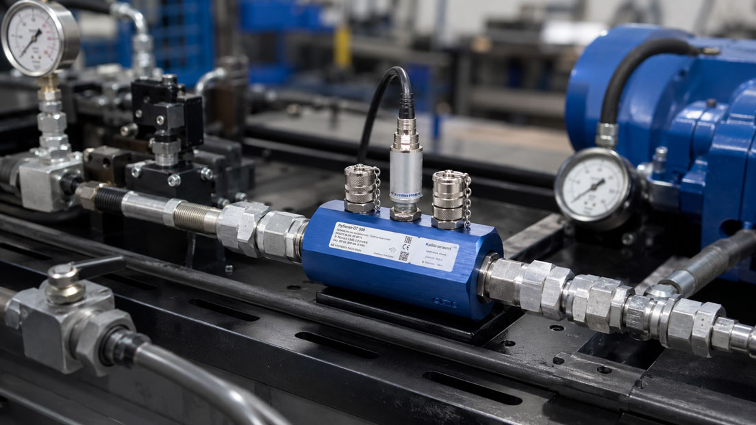
Hydraulic systems only work reliably when pressure and flow rate match. Too little flow can indicate worn pumps, internal leakage, clogged filters, incorrectly adjusted valves or unfavorable operating conditions. Too much or strongly fluctuating flow can stress components, waste energy or make control loops unstable. For maintenance, test benches, commissioning and troubleshooting, flow measurement of hydraulic oil is therefore a central measuring task.
Flow turbines are a very common and practical solution for hydraulic oil. They provide a frequency- or pulse-based signal that is proportional to the volume flow. This makes them well suited for mobile hydraulic measurement technology, test benches, pump tests, valve tests and continuous measurements in industrial hydraulic systems. At the same time, several points must be considered during selection so that the measured values are reliable.
This article explains what matters when using flow turbines for hydraulic oil. The focus is on oil viscosity, temperature dependence, pressure range, pressure loss, filtration, contamination, pulsation, measuring range, connection threads, installation position, signal processing and typical measurements on pumps, valves, test benches and mobile hydraulic systems.
Table of contents
- Basics: how does a flow turbine work with hydraulic oil?
- Hydraulic oil as a medium: why viscosity and temperature are decisive
- Measuring range: selecting minimum and maximum flow correctly
- Pressure range and pressure spikes in hydraulic systems
- Pressure loss: why the flow turbine must match the system
- Filtration and contamination: protecting the turbine and measurement accuracy
- Pulsation, vibrations and dynamic hydraulic processes
- Connection threads, installation position and mechanical integration
- Measurement on pumps, valves and test benches
- Signal processing: pulses, frequency, display and PLC connection
- Temperature measurement and correction of oil viscosity
- Typical errors with flow turbines in hydraulic oil
- Practical example: volume flow test on a hydraulic pump
- Which measuring instruments / products are suitable?
- Conclusion: flow turbines are strong when oil condition and application range fit
- FAQ: frequently asked questions about flow turbines for hydraulic oil
Basics: how does a flow turbine work with hydraulic oil?
A flow turbine measures volume flow by using the hydraulic oil to drive a turbine wheel inside the measuring body. Within the suitable measuring range, the rotational speed of the turbine is proportional to the flow velocity and therefore to the volume flow. A sensor detects the rotational movement and generates a pulse or frequency signal from it.
The major advantage of this measuring principle lies in the direct, fast and easily evaluable signal form. Flow turbines respond dynamically, provide a clear frequency signal and can be connected to displays, data loggers, test benches or control systems. This is particularly interesting for hydraulic oil because pumps, valves and consumers often need to be tested under real operating conditions.
At the same time, the flow turbine is a mechanical measuring principle. This means: the medium must be clean enough, the viscosity must match the measuring range, the pressure loss must not disturb the system and the flow must remain within the specified range. If the turbine is used outside its suitable operating conditions, measurement errors, increased wear or damage can occur.
For hydraulic oil, a flow turbine is particularly suitable when a defined volume flow needs to be measured and the oil is sufficiently filtered. For heavily contaminated, highly viscous, pulsating or extremely variable media, the application must be checked more closely.
| Characteristic | Meaning with flow turbines | Practical relevance with hydraulic oil |
|---|---|---|
| Turbine wheel | Driven by the flowing oil | Requires a clean medium and suitable flow range. |
| Frequency signal | Rotational speed is output as a pulse or frequency signal | Well suited for displays, data loggers and test benches. |
| Measuring range | Reliable only within the specified range | Minimum and maximum volume flow must match the system. |
| Pressure loss | A flow-through measuring device creates additional resistance | Must be considered for pump and test bench measurements. |
| Medium condition | Viscosity, temperature and contamination influence the measurement | Oil temperature and filtration are decisive selection points. |
Hydraulic oil as a medium: why viscosity and temperature are decisive
Hydraulic oil is not a constant medium. Its viscosity changes significantly with temperature. Cold oil is more viscous and creates higher friction, higher pressure loss and different turbine start-up behavior. Warm oil is thinner and flows more easily through the measuring device. Therefore, measured values and response behavior can differ depending on oil temperature.
Viscosity mainly influences the lower measuring range. At higher viscosity, the turbine may require more energy from the oil flow to start properly and rotate stably. If the minimum flow is not reached, the measurement can become inaccurate or the signal can appear unstable. This effect is particularly important with cold hydraulic oil after system start-up.
The oil type also plays a role. Mineral hydraulic oils, synthetic oils, bio-oils or fire-resistant hydraulic fluids can have different viscosity and lubrication characteristics. Additives, aging products or contamination can also influence the measurement. The flow turbine should therefore not be selected only according to the pipeline, but according to the specific oil and operating condition.
For meaningful hydraulic measurements, the oil temperature should ideally be recorded or at least documented. A volume flow value without temperature information is often difficult to evaluate because pump performance, leakage behavior, pressure loss and viscosity change with temperature.
| Influencing factor | Effect on hydraulic oil | Consequence for the flow turbine |
|---|---|---|
| Low temperature | Oil becomes more viscous | Higher pressure loss, more difficult start-up behavior, greater measurement uncertainty in the lower range. |
| High temperature | Oil becomes thinner | Flow increases more easily, leaks in pumps or valves can become more visible. |
| Oil type | Viscosity and additives differ | Check media compatibility and calibration conditions. |
| Oil aging | Viscosity and contamination can change | Measurement can provide indications of changed operating conditions. |
| Air in the oil | Compressibility and signal behavior change | Measured value may fluctuate or become implausible. |
Measuring range: selecting minimum and maximum flow correctly
The measuring range is one of the most important selection criteria. A flow turbine should not only be able to capture the expected maximum flow, but also measure accurately enough in the normal working range. If a turbine is selected too large, the actual volume flow may often be close to the lower limit. The signal then becomes weaker and the measurement less stable.
If the turbine is selected too small, pressure loss increases and the turbine may be overloaded at high flow rates. This can cause measurement errors, mechanical stress or premature wear. The expected operating range should therefore be known as precisely as possible.
With hydraulic pumps, the theoretical delivery flow can often be calculated from displacement volume and speed. In practice, the real volume flow deviates from this due to leakage, pressure, temperature and wear. For selecting the flow turbine, not only the pump’s nominal value should be considered, but the expected real measuring range.
On test benches, it is useful to select the flow turbine so that typical test points lie in the middle measuring range. The measuring device usually works more stably there than directly at the range limits. For very different flow ranges, several measuring ranges or interchangeable sensors may be useful.
Pressure range and pressure spikes in hydraulic systems
Hydraulic systems often operate with high working pressures. In addition, pressure spikes can occur due to valve switching, load changes, pump pulsation, fast movements or blocked consumers. A flow turbine must therefore be designed not only for normal operating pressure, but also for possible pressure spikes and safety margins.
The permissible pressure range concerns the measuring body, connections, seals and the entire mechanical design. If a flowmeter is installed in a high-pressure line, the pressure rating and connection type must clearly match the system. Especially for mobile hydraulic testing, it is important that the measuring device, hoses, couplings and adapters meet the same pressure requirements.
The operating pressure also influences the interpretation of the measured result. A pump may still provide sufficient volume flow at low pressure, but drop significantly at higher pressure due to internal leakage. For this reason, flow measurement in hydraulics is often only meaningful when pressure and temperature are considered at the same time.
In dynamic systems, pressure cycling should also be taken into account. A flow turbine that is sufficiently pressure-resistant under static conditions can be additionally stressed by strong pulsation or frequent load changes. The installation situation and test procedure should therefore match the mechanical load capacity of the measuring device.
| Pressure-related point | Why important? | Practical recommendation |
|---|---|---|
| Operating pressure | Measuring body and connections must be pressure-resistant | Select pressure rating to match the hydraulic system. |
| Pressure spikes | Can be significantly above normal pressure | Consider reserve and dynamic load. |
| Test pressure | Often higher or deliberately loaded on test benches | Design measuring device and accessories together. |
| Adapters and couplings | The weakest component determines safety | Check pressure class of the entire measuring chain. |
| Parallel pressure measurement | Flow without pressure is often difficult to interpret | Evaluate pressure, volume flow and temperature together. |
Pressure loss: why the flow turbine must match the system
A flow turbine is flowed through by the hydraulic oil and therefore creates a pressure loss. This pressure loss depends on nominal size, flow, oil viscosity, temperature and design. In many applications the pressure loss is uncritical, but in test benches or sensitive hydraulic circuits it can influence the measurement result or system behavior.
With cold oil, pressure loss increases because the viscosity is higher. This can be particularly relevant during system start-up or mobile testing outdoors. If the measuring device is sized too small, pressure loss can increase further and place more load on the system.
In pump tests, it must be considered whether the flowmeter is located in the pressure line, return line or in a bypass/test line. Depending on the installation point, pressure loss can be critical to different degrees. In a pressure line, additional resistance can influence pump behavior. In the return line, excessive back pressure may also be undesirable.
The flow turbine should therefore not only be selected according to suitable volume flow, but also according to permissible pressure loss. In critical applications, pressure loss should be considered over the entire operating range, especially at low oil temperature and high flow.
Filtration and contamination: protecting the turbine and measurement accuracy
Hydraulic oil should be clean, but in real systems particles, abrasion, seal residues, metal chips, dirt or aging products can occur. Contamination is particularly important for flow turbines because the turbine wheel and bearings are mechanically stressed. Particles can slow down, damage or block the turbine.
Suitable filtration protects the measuring device and improves measurement stability. In many hydraulic systems, filters are already part of the system. For mobile measurements or test bench measurements, it should nevertheless be checked whether the measuring point is before or after the filter and which cleanliness class can be expected.
Contamination can also gradually affect the measurement. If the turbine no longer runs freely, the displayed volume flow may be too low or the signal may become unstable. Especially for recurring tests, plausibility, signal behavior and the condition of the flow turbine should therefore be monitored.
If heavily contaminated oil, flushing processes or systems with unknown oil condition are to be measured, the suitability of the flow turbine must be checked critically. Additional filters, flushing or a different measuring principle may be more suitable.
| Type of contamination | Possible effect | Test approach |
|---|---|---|
| Metal particles | Damage to turbine wheel or bearing | Check filtration and oil condition. |
| Seal residues | Blockage or uneven running | Inspect measuring device after critical system conditions. |
| Oil aging products | Deposits or more viscous flow | Consider oil condition, temperature and viscosity. |
| Air bubbles | Fluctuating measured values and unstable signal | Check suction side, venting and return conditions. |
| Unknown system contamination | Increased risk of measurement errors or damage | Check prefiltration or alternative measurement strategy. |
Pulsation, vibrations and dynamic hydraulic processes
Hydraulic systems are often dynamic. Pumps generate pulsations, valves switch, cylinders move loads and control loops change the volume flow. A flow turbine can generally detect fast changes well, but strong pulsation can make the signal unstable and interpretation more difficult.
With pumps that have pronounced pulsation, the instantaneous volume flow can fluctuate even though the average volume flow appears stable. Depending on the display or evaluation device, this can lead to jumping values. In such cases, averaging, suitable sampling rates or a measuring setup with damping can be useful.
Mechanical vibrations can also play a role. If the flow turbine is installed rigidly in a vibrating line, the sensor, cable and connections can be stressed. Flexible lines, suitable supports and low-stress installation help reduce mechanical loads.
For test benches, it is important whether the instantaneous value or the average flow value is required. When assessing a pump, a stable average value may be sufficient. When analyzing a control valve or a fast switching movement, the dynamic signal itself may be of interest.
Connection threads, installation position and mechanical integration
The mechanical integration of a flow turbine is particularly important in hydraulic applications. Connection threads, sealing surfaces, adapters, hose lines, couplings and installation position must match the system. A mechanically fitting connection is not enough if pressure class, flow direction or sealing concept are incorrect.
Many flow turbines have a defined flow direction. This must be observed during installation. If the device is installed the wrong way around, the measured value may become implausible or the turbine may not work correctly. The flow direction should therefore be checked before commissioning.
The installation position may also be relevant. Although many hydraulic flow turbines are designed robustly, it should be avoided that air bubbles remain permanently in the measuring body or that dirt collects in unfavorable areas. For mobile measurements, the measuring device should be positioned so that lines do not pull, kink or mechanically load the device.
Special care is required with connection adapters. Every adapter creates additional sealing points, possible pressure losses and potential leakage points. For safe measurements, the entire connection chain consisting of flow turbine, coupling, hose and adapter must be suitable for pressure, medium and temperature.
| Mechanical point | Why relevant? | Typical consequence of errors |
|---|---|---|
| Connection thread | Must match system and pressure class | Leakage, incorrect adapters or safety risk. |
| Flow direction | Turbine is usually direction-dependent | Incorrect or unstable measured values. |
| Installation position | Influences air, dirt and mechanical stress | Signal disturbances or unnecessary stress. |
| Hoses and couplings | Determine pressure resistance and practical usability | Leaks, pressure loss or safety problems. |
| Mechanical support | Prevents tensile and bending loads | Damage to connection, sensor or line. |
Measurement on pumps, valves and test benches
One of the most important applications for flow turbines is testing hydraulic pumps. The volume flow is measured at a defined pressure, defined speed and known oil temperature. If the volume flow drops sharply as pressure increases, this can indicate internal leakage or pump wear.
In valve testing, flow measurement helps assess opening behavior, leakage, throttling effect or switching states. Especially with proportional valves or servo valves, the relationship between control signal, pressure difference and volume flow can be decisive. A flow turbine provides a fast and easily evaluable flow signal for this purpose.
On hydraulic test benches, flow turbines are often used for performance evaluation and documentation. It is important that measuring range, pressure rating, oil temperature, calibration and signal processing are clearly defined. Only then can measurement results be compared between tests or systems.
Flow turbines are also very useful in mobile maintenance. A service technician can check the volume flow of a machine under load and assess whether pump performance, valve function or consumers match the expected condition. A safe measuring setup with suitable hoses, couplings and pressure measurement is important here.
| Measuring point | Typical question | Important additional variable |
|---|---|---|
| Pump outlet | Does the pump deliver the expected volume flow? | Pressure, speed and oil temperature. |
| Valve circuit | Does the valve open or throttle correctly? | Control signal and pressure difference. |
| Return line | How much oil flows back to the tank? | Return pressure and temperature. |
| Test bench | Is the hydraulic component within specification? | Calibration status and defined test conditions. |
| Mobile machine | Is there performance loss or internal leakage? | Load condition, pressure and operating temperature. |
Signal processing: pulses, frequency, display and PLC connection
Flow turbines usually provide a pulse or frequency signal. The frequency increases with the volume flow. A K-factor is often used for evaluation; it indicates how many pulses are generated per volume unit. The evaluation device calculates the current volume flow and, if applicable, a total quantity from this.
For mobile measurements, the signal is often connected to a handheld measuring device or data logger. For test benches, it can be integrated directly into test bench software or a PLC. It is decisive that K-factor, unit, measuring range and signal type are parameterized correctly. An incorrect K-factor directly leads to incorrect volume flow values.
For PLC connections, the frequency signal can be evaluated directly or converted into an analog signal via a transmitter. If a 4–20 mA signal is used, the scaling must be clearly defined. 4 mA and 20 mA must correspond to a clear flow range. Otherwise, the turbine measures correctly, but the control system displays incorrect values.
The UPS4E loop calibrator is suitable for testing 4–20 mA signals. It can be used to measure or simulate current loops and detect scaling errors between transmitter, display, PLC and control system. For the pure frequency or pulse signal, however, a suitable frequency meter, counter or data logger is relevant.
Temperature measurement and correction of oil viscosity
Oil temperature should always be considered in hydraulic flow measurements. Many measurement results are only meaningfully comparable if they were taken at similar temperatures. A pump can behave differently with cold oil than in warm operating condition. Leaks in pumps or valves also often increase with warm, thinner oil.
On test benches, temperature is therefore often measured and documented. For mobile measurements, at least the oil temperature should be recorded at a suitable point. If volume flow values are to be compared over longer periods, a defined temperature condition is particularly important.
Temperature affects not only the pump, but also the pressure loss of the flow turbine. With cold oil, a measuring device that fits well at operating temperature can create significantly more resistance. This can make the measuring setup influence system behavior more strongly.
In very temperature-critical applications, it should be checked whether additional temperature compensation, a defined warm-up phase or another measuring concept is required. For many maintenance tasks, however, it is already sufficient to document pressure, flow and temperature together and not evaluate them in isolation.
Typical errors with flow turbines in hydraulic oil
A common error is selecting a flow turbine that is too large. It may fit mechanically into the line, but in real operation it often works close to the lower measuring range. This can cause unstable signals or less accurate measured values. Conversely, a turbine that is too small can create unnecessary pressure loss at high flow rates or be overloaded.
Another error is neglecting oil temperature. If a measurement with cold oil is compared with a measurement on a warm system, differences may be wrongly interpreted as a pump problem. Temperature and viscosity must therefore always be included in the evaluation.
Contamination is also frequently underestimated. Particles in hydraulic oil can influence or damage the turbine wheel. If the flow turbine suddenly indicates less, the cause may be the system, but also the measuring device itself. A plausibility check and regular inspection are therefore useful.
Signal errors are also typical. Incorrect K-factor, wrong unit, unsuitable input on the data logger, missing pulse counting or incorrect 4–20 mA scaling can lead to wrong measured values. The electrical evaluation should therefore be checked just as carefully as the hydraulic installation.
| Error pattern | Possible cause | Test approach |
|---|---|---|
| Measured value too low | Contaminated turbine, incorrect K-factor or pump wear | Check measuring device, signal parameterization and pump condition. |
| Measured value fluctuates strongly | Pulsation, air in the oil, unstable flow or signal problem | Check oil condition, venting, averaging and signal path. |
| High pressure loss | Flow turbine too small, oil too cold or flow too high | Reassess nominal size, oil temperature and operating range. |
| No display | No signal, incorrect wiring or turbine blocked | Check sensor supply, frequency input and mechanical running. |
| PLC value is incorrect | Incorrect scaling or incorrect signal conversion | Check K-factor, analog range and parameterization. |
Practical example: volume flow test on a hydraulic pump
In a mobile working machine, a loss of performance is detected. The cylinders move more slowly than usual, although the system pressure is sometimes still reached. To check whether the hydraulic pump delivers sufficient flow, a flow turbine is installed in the test circuit.
The measurement is carried out at a defined speed, known pressure and documented oil temperature. First, the volume flow is checked at low back pressure. Then the pressure is increased to assess behavior under load. It becomes apparent that the volume flow drops significantly more than expected as the load increases.
The combination of pressure, volume flow and temperature indicates increased internal leakage of the pump. Without flow measurement, the cause would have been more difficult to detect because the pressure alone still seemed plausible at times. The flow turbine therefore provides an important diagnostic variable for maintenance.
After repair, the measurement is repeated under comparable conditions. The volume flow is again within the expected range. The example shows why hydraulic measurements should always consider several variables: flow, pressure, temperature and operating condition together create a meaningful picture.
Which measuring instruments / products are suitable?
The category flow turbines is the right starting point when volume flow in hydraulic oil, test benches, mobile hydraulic systems or industrial applications needs to be measured. Flow turbines are particularly interesting when a fast pulse or frequency signal is required and the medium is sufficiently clean.
The higher-level category flow measurement technology provides a broader overview of different measuring principles. This is helpful when checking whether a flow turbine, oval gear meter, electromagnetic flowmeter, Coriolis system, ultrasonic flowmeter or another principle is better suited to the application.
For hydraulic oil, the flow turbine is particularly suitable when the volume flow is within a defined measuring range, the oil is filtered and pressure range, temperature and viscosity match the size. For very contaminated, strongly pulsating or extremely viscous media, the application should be checked more closely.
For test benches and mobile measurements, additional pressure sensors, temperature probes, data loggers, displays, frequency inputs and suitable hydraulic hoses may be required. Only the combination of volume flow, pressure and temperature makes the hydraulic measurement truly meaningful.
If the turbine signal is output via a transmitter as a 4–20 mA signal, the UPS4E loop calibrator can be used to test the analog signal path. For pure pulse or frequency signals, however, suitable counters, frequency inputs or data loggers are decisive.
| Product / area | Typical use | Particularly relevant for |
|---|---|---|
| Flow turbines | Volume flow measurement with turbine wheel and frequency signal | Hydraulic oil, test benches, mobile hydraulics, pump and valve tests |
| Flow measurement technology | Overview of different flow measurement principles | Selection between flow turbine, oval gear, electromagnetic flowmeter, Coriolis, ultrasonic and other principles |
| Pressure sensors | Additional pressure measurement in the hydraulic circuit | Pump testing, valve assessment, load condition and leakage analysis |
| Temperature probes | Recording the oil temperature | Viscosity assessment, comparability and test bench documentation |
| UPS4E loop calibrator | Testing of 4–20 mA signals after signal conversion | PLC connection, scaling check and troubleshooting in analog measuring chains |
Conclusion: flow turbines are strong when oil condition and application range fit
Flow turbines are a very practical solution for hydraulic oil when volume flow needs to be measured quickly, reproducibly and in a way that is easy to evaluate. They are particularly suitable for pump tests, valve tests, mobile hydraulic diagnostics, test benches and industrial systems where clean oil and defined operating conditions are present.
Correct sizing is decisive, however. Measuring range, pressure range, pressure loss, viscosity, oil temperature, filtration, contamination, pulsation, connection thread and signal processing must match. A flow turbine that mechanically fits into the line is not automatically the right solution for the measurement task.
The most important recommendation is: always consider hydraulic flow measurement as a combination of volume flow, pressure and temperature. Only this allows pump performance, valve behavior, internal leakage and system condition to be assessed reliably. When these framework conditions are right, the flow turbine is a very valuable tool for maintenance, testing and process monitoring.
FAQ: frequently asked questions about flow turbines for hydraulic oil
Can hydraulic oil be measured with a flow turbine?
Yes, flow turbines are very suitable for hydraulic oil when measuring range, viscosity, pressure range, temperature and oil cleanliness match the application.
What does a flow turbine measure?
A flow turbine measures volume flow. The flowing oil drives a turbine wheel whose rotational speed is evaluated as a pulse or frequency signal.
Why is viscosity important with hydraulic oil?
Viscosity influences start-up behavior, pressure loss and measurement accuracy. Cold oil is more viscous and can influence the measurement more strongly than warm oil.
Why should oil temperature also be measured?
Temperature changes the viscosity of the oil and therefore pump behavior, pressure loss and leakage. Flow values are often difficult to compare without temperature information.
What happens if the flow turbine is selected too large?
The actual flow may then be close to the lower measuring range. This can lead to unstable signals or less accurate measured values.
What happens if the flow turbine is selected too small?
A turbine that is too small can create high pressure loss or be overloaded at high flow rates. This can cause measurement errors or damage.
How important is the pressure range?
Very important. Measuring body, connections, seals, hoses and adapters must match the operating pressure and possible pressure spikes of the hydraulic system.
Does a flow turbine create pressure loss?
Yes. Every flow-through turbine creates a pressure loss. This depends on flow, oil viscosity, temperature and size.
Can contaminated hydraulic oil damage a flow turbine?
Yes. Particles, metal abrasion or seal residues can affect or damage the turbine wheel and bearings. Suitable filtration is therefore important.
How can air in hydraulic oil be detected?
Air in the oil can cause fluctuating measured values, unstable signals, noise and uneven system behavior. Venting and suction conditions should be checked.
What is the K-factor of a flow turbine?
The K-factor describes how many pulses are generated per volume unit. It is decisive for correctly converting the frequency signal into volume flow.
Can a flow turbine be connected to a PLC?
Yes, depending on signal and input, the frequency signal can be evaluated directly or converted via a transmitter into an analog signal such as 4–20 mA.
How do you test a 4–20 mA signal from a flow transmitter?
A loop calibrator can be used to measure or simulate the signal. This makes it possible to detect scaling errors between transmitter, display and PLC.
Where is a flow turbine installed in hydraulics?
Depending on the measurement task, it can be installed in the pressure line, return line, test line or test bench. The installation point must match pressure, flow direction and measurement objective.
Can pump wear be detected with it?
Yes. If the volume flow drops more than expected as pressure increases, this can indicate internal leakage or pump wear.
Can valves be tested with a flow turbine?
Yes. Flow turbines can help assess valve opening, throttling effect, leakage or the behavior of proportional and servo valves.
Are flow turbines suitable for mobile hydraulic diagnostics?
Yes, they are often used in mobile hydraulic diagnostics. Suitable pressure rating, hoses, couplings, safe installation and a suitable display are important.
When is another measuring principle better?
If the oil is heavily contaminated, the flow pulsates strongly, the viscosity is extremely high or pressure loss is very critical, an alternative measuring principle should be checked.
Which information is required for selection?
Important information includes medium, oil type, viscosity, temperature range, flow range, operating pressure, pressure spikes, connection thread, filtration, installation situation and desired output signal.
Which products are suitable for hydraulic oil flow measurements?
Suitable products are flow turbines with matching measuring range, pressure range, connection and signal. Pressure sensors, temperature probes, displays or data loggers are useful additions for fully evaluating the hydraulic system.