


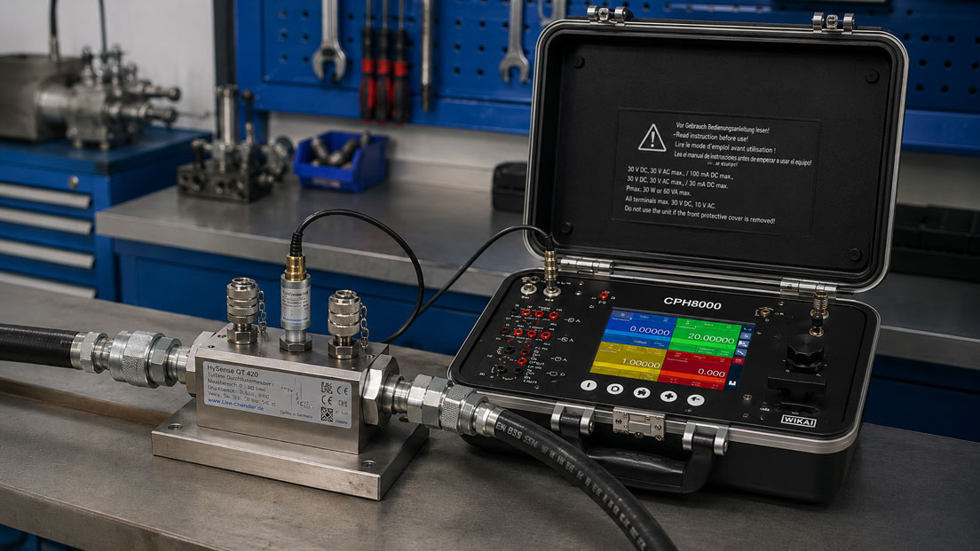
Flow turbines are often used when liquids or gases need to be measured dynamically and with a signal that is easy to evaluate. A key advantage of this measuring principle is the pulse or frequency output. The rotational speed of the turbine wheel is converted into electrical pulses. The faster the medium flows, the higher the frequency of the output signal.
For many users, the actual challenge is not the mechanical installation of the flow turbine, but the evaluation of the signal. What does the K-factor mean? How are pulses per liter converted into a volume flow? Which PLC input is suitable? Why does the control system show incorrect values although the flow turbine is installed correctly? And what role do limit frequency, cables, shielding and signal quality play?
This article explains how pulse and frequency outputs on flow turbines work and how a correct flow value is calculated from them. The focus is on K-factor, pulses per liter, frequency signal, counter function, PLC connection, measured value conversion, limit frequency, signal quality, cables and shielding as well as typical errors during commissioning of turbine flowmeters.
Table of contents
- Basics: why flow turbines provide a pulse or frequency signal
- Operating principle: from turbine wheel to electrical signal
- K-factor: understanding pulses per liter correctly
- Calculating flow from frequency
- Calculating total quantity from pulses
- PLC connection: frequency input, counter or high-speed counter?
- Signal types: NPN, PNP, open collector, Namur and push-pull
- Limit frequency, minimum flow and resolution
- Averaging, filtering and response time
- Cables, shielding and EMC: ensuring signal quality
- Scaling in display, PLC and control system
- Conversion into 4–20 mA or other output signals
- Typical errors when evaluating flow turbines
- Practical example: calculating the frequency signal of a flow turbine
- Which measuring instruments / products are suitable?
- Conclusion: evaluate frequency signals only with the correct K-factor
- FAQ: frequently asked questions about pulse and frequency outputs on flow turbines
Basics: why flow turbines provide a pulse or frequency signal
A flow turbine measures the volume flow via the movement of a turbine wheel in the flow channel. The medium sets the turbine wheel in rotation. Within the specified measuring range, the rotational speed is proportional to the flow velocity and therefore to the volume flow. This movement is detected by a sensor and output as an electrical signal.
In many applications, this signal is a pulse or frequency signal. Each pulse corresponds to a small partial volume. The more volume flows through the flow turbine per unit of time, the more pulses are generated per second. The frequency of the signal is therefore directly linked to the current flow rate.
This is particularly advantageous for test benches, dosing systems, filling processes, hydraulic measurements, process monitoring and PLC connections. A frequency signal can respond quickly, is easy to count and can be used both for instantaneous values and for total quantities.
However, in order to obtain a correct flow value from the signal, the K-factor must be stored correctly. Without the K-factor, the display or control system may know how many pulses are arriving, but not which volume these pulses correspond to. The K-factor is therefore the central parameter when evaluating flow turbines.
| Term | Meaning | Practical benefit |
|---|---|---|
| Pulse output | Outputs individual electrical pulses | Suitable for quantity counting and simple flow evaluation. |
| Frequency output | Pulses per second correspond to the current flow rate | Well suited for instantaneous flow and dynamic processes. |
| K-factor | Specifies how many pulses correspond to one volume unit | Basis for conversion into l/min, m³/h or total quantity. |
| Counter function | Counts the total number of pulses | Determination of total volume, batch quantity or dosing quantity. |
| Frequency measurement | Determines pulses per time unit | Calculation of the current flow rate. |
Operating principle: from turbine wheel to electrical signal
Inside the flow turbine there is a rotor or turbine wheel. The medium flows through the measuring body and drives this rotor. The higher the volume flow, the faster the turbine rotates. Depending on the design of the flow turbine, the rotation is detected by a magnetic, inductive, Hall-based or other sensor system.
The sensor element detects the movement of the turbine blades or a magnetic element and generates electrical pulses from it. With constant flow, a regular frequency signal is produced. With changing flow, the frequency changes accordingly.
For evaluation, it is important that the signal is not simply understood as “voltage”. A flow turbine with pulse output does not provide an analog signal that can be measured directly as a proportional voltage. Instead, it is necessary to count how many pulses arrive per unit of time or how many pulses have been counted in total.
At very low flow rates, only a few pulses are generated per unit of time. This can make the measured value appear more jumpy or update more slowly. At high flow rates, the frequency increases. It must then be ensured that the input, display or PLC can reliably detect this frequency.
K-factor: understanding pulses per liter correctly
The K-factor is the most important parameter for converting the turbine signal. It indicates how many pulses the flow turbine generates per volume unit. It is often specified in pulses per liter, for example 1,000 pulses/liter. Depending on the device and calibration, other units may also be used, such as pulses per milliliter, pulses per gallon or pulses per cubic meter.
If the K-factor is 1,000 pulses per liter, this means: after 1,000 counted pulses, one liter of medium has flowed through the turbine. If 50 pulses per second are measured, this corresponds to 50 pulses per second. The instantaneous flow rate can be calculated from this using the K-factor.
The K-factor can be specified as a nominal value in the data sheet or as an individual calibration value on the calibration certificate. In more precise applications, the calibrated K-factor is particularly important. It can vary depending on medium, viscosity, measuring range and calibration conditions.
An incorrect K-factor directly leads to incorrect measured values. The flow turbine can work mechanically perfectly, the PLC can count pulses correctly and yet an incorrect flow rate is displayed if the K-factor was entered incorrectly or the unit is wrong.
| K-factor specification | Meaning | Typical conversion error |
|---|---|---|
| Pulses/liter | Number of pulses per liter of flow | Accidentally interpreted as pulses per minute. |
| Pulses/ml | Number of pulses per milliliter | Factor 1,000 is forgotten when calculating liters. |
| Pulses/m³ | Number of pulses per cubic meter | Conversion into liters or m³/h is scaled incorrectly. |
| Calibrated K-factor | Individually determined value of the specific sensor | Only a general data sheet value is used instead. |
| Multipoint K-factor | K-factor can vary depending on flow range | Only one value is used although linearization would be required. |
Calculating flow from frequency
The current flow rate is calculated from the measured frequency and the K-factor. The frequency describes how many pulses arrive per second. If the K-factor is specified in pulses per liter, the flow in liters per second is obtained by dividing the frequency by the K-factor.
The basic formula is:
Flow [L/s] = frequency [Hz] / K-factor [pulses/L]
Since liters per minute are frequently used in practice, the value is then multiplied by 60:
Flow [L/min] = frequency [Hz] × 60 / K-factor [pulses/L]
For cubic meters per hour, liters must also be converted into cubic meters. Since 1 m³ = 1,000 liters, the result is:
Flow [m³/h] = frequency [Hz] × 3.6 / K-factor [pulses/L]
These formulas are simple, but they are only correct if frequency and K-factor are used in matching units. This is exactly where many errors occur. Confusion between pulses per liter and pulses per milliliter or between seconds, minutes and hours is particularly critical.
| Target value | Formula with K-factor in pulses/liter | Note |
|---|---|---|
| Liters per second | Q [L/s] = f / K | Direct conversion from Hz. |
| Liters per minute | Q [L/min] = f × 60 / K | Common unit for test benches and hydraulics. |
| Cubic meters per hour | Q [m³/h] = f × 3.6 / K | Typical in process and energy applications. |
| Frequency from flow | f [Hz] = Q [L/s] × K | Helpful for simulation and plausibility checking. |
| Checking K-factor | K = f / Q [L/s] | Only useful with a known reference quantity. |
Calculating total quantity from pulses
In addition to the current flow rate, the total quantity can also be calculated from the pulse signal. For this, the frequency is not considered, but the total number of counted pulses. The calculation is directly linked to the K-factor.
If the K-factor is specified in pulses per liter, the following applies:
Total quantity [L] = counted pulses / K-factor [pulses/L]
Example: if a flow turbine has a K-factor of 1,000 pulses per liter and a counter registers 25,000 pulses, 25 liters have been measured. This function is particularly useful for dosing processes, filling operations, test bench cycles or consumption measurements.
For quantity counting, it is important that no pulses are lost. The input must be fast enough, the signal must be clean and interference must not be counted as additional pulses. At high frequencies or over long cable runs, particular attention should therefore be paid to input type, debounce, filtering and shielding.
Quantity measurement can be very precise if the K-factor is correct and all pulses are counted correctly. However, it can become clearly wrong if signal edges are not detected, interference pulses are counted or K-factor and unit are parameterized incorrectly.
PLC connection: frequency input, counter or high-speed counter?
When connecting a flow turbine to a PLC, the correct input is decisive. A normal digital input is not automatically suitable for reliably detecting fast pulses. At higher frequencies, the PLC may miss pulses due to the cycle time. A fast counter input or high-speed counter is then required.
For instantaneous flow measurement, the PLC can either measure the frequency or count the pulses within a defined time window. The flow is then calculated from the number of pulses per time unit. For the total quantity, the sum of the pulses is counted and divided by the K-factor.
The PLC programmer must know whether the input should respond to the rising edge, falling edge or both edges. It must also be clarified whether the signal is active or passive, which supply voltage is used and whether the sensor has an NPN, PNP, open collector, push-pull or another type of output.
For test benches and fast processes, the update time is also important. A short measuring period provides fast response, but can fluctuate more strongly. A longer measuring period smooths the value, but reacts more slowly. The correct setting depends on whether a stable average value or fast dynamics are required.
| PLC function | Suitable for | Important point |
|---|---|---|
| Digital input | Slow pulses or simple states | Cycle time can lead to pulse loss at higher frequencies. |
| Fast counter input | Pulse counting and total quantity | Check maximum input frequency. |
| Frequency input | Instantaneous flow | Select measuring window and update time appropriately. |
| High-speed counter | Fast turbine signals | Especially important at high flow rates and high pulse counts. |
| Analog converter | Conversion into 4–20 mA or voltage | Scaling and dynamics must match the application. |
Signal types: NPN, PNP, open collector, Namur and push-pull
Depending on the version, flow turbines can provide different output signals. A pulse output must therefore not be understood as a universal digital signal in general. Before wiring, it must be clarified which signal type is present and which input is compatible with it.
PNP outputs typically switch to plus, NPN outputs to minus. Open-collector outputs often require a pull-up resistor or a suitable input. Push-pull outputs can actively switch in both directions. Namur signals are often used in industrial or explosion-proof applications and require a suitable evaluation unit.
If output and input do not match, the signal may be missing, inverted, too small or unstable. In some cases, pulses are only detected at certain flow rates or the PLC counts interference pulses. The electrical interface should therefore always be checked using the data sheet, wiring diagram and input specification.
The supply voltage is also important. Some sensors require a defined auxiliary power supply, while others operate passively. An incorrect supply can lead to no signal, malfunction or damage. In case of uncertainty, the interface should be checked with a suitable measuring instrument or signal generator before commissioning.
Limit frequency, minimum flow and resolution
Every flow turbine has a specified measuring range. At very low flow rates, the turbine wheel rotates slowly or may not start reliably. As a result, only a few pulses are generated per unit of time. The frequency is low and the resolution of the measured value becomes poorer. Especially at low flow rates, the display may therefore jump or react slowly.
At high flow rates, the frequency increases. The flow turbine, sensor, cable, display and PLC input must then be suitable for the maximum frequency. If the input can no longer reliably detect the frequency, pulses are lost and the displayed flow is too low.
The limit frequency therefore does not only concern the flow turbine itself, but the entire signal chain. A sensor can provide a clean signal, but a slow PLC input can still cause measurement errors. Likewise, a display may only be designed for a certain input frequency.
For selection, the expected maximum flow should therefore be converted into a maximum frequency. This frequency can be used to check whether input, counter or evaluation device are fast enough. At the same time, the minimum flow should be considered so that enough pulses are still generated in the lower range for a stable measurement.
| Range | What happens? | Effect on evaluation |
|---|---|---|
| Below minimum flow | Turbine does not run stably or does not start | Measured value inaccurate, fluctuating or zero. |
| Low flow | Few pulses per unit of time | Poorer resolution and slower update. |
| Normal measuring range | Frequency proportional to flow | Good evaluation with K-factor possible. |
| High flow | High signal frequency | Check input frequency of PLC or display. |
| Above maximum flow | Turbine can be overloaded | Measurement errors, wear or damage possible. |
Averaging, filtering and response time
Frequency signals from flow turbines can react very quickly to flow changes. This is an advantage in dynamic processes. At the same time, the displayed value can fluctuate strongly with pulsating flows, low frequencies or an unstable process. For this reason, averaging or filtering is often used.
Averaging can be performed over a time window. The display or PLC counts the pulses within this window and calculates the flow from them. A short window reacts quickly, but provides a more unstable value. A long window smooths more strongly, but reacts more slowly to real changes.
For quantity counting, a different view is important. For the total quantity, all valid pulses should be counted. Excessive filtering or incorrect debounce can suppress pulses here. Conversely, interference can be counted as additional pulses if the input is too sensitive or poorly shielded.
The filter setting should therefore match the application. In dosing, fast and complete pulse counting can be decisive. In a process display, a stable instantaneous value may be more important. On a test bench, dynamics and reproducibility must be weighed against each other.
Cables, shielding and EMC: ensuring signal quality
The pulse or frequency signal of a flow turbine can be affected by electrical interference. Especially in industrial environments with motors, frequency converters, contactors, long cables, pumps, valves or welding systems, clean wiring is important. Otherwise, interference pulses may be counted as genuine flow pulses.
A shielded cable is often useful, especially for longer cable runs or low signal levels. The shield must be connected correctly. Incorrect shielding can even promote interference or create ground loops. Separating signal and power cables is also important.
Signal ground, supply, input type and potential references must match. With open-collector or Namur signals, the correct evaluation unit is decisive. With PNP or NPN signals, the PLC input must be designed accordingly.
During troubleshooting, the flow turbine itself should not be the only focus. If the flow value jumps although the process is stable, cables, shielding, input, supply, grounding or EMC interference may be the cause. Testing with a signal generator or simulator can help separate the electrical evaluation from the mechanical measuring point.
| Signal problem | Possible cause | Test approach |
|---|---|---|
| Additional pulses | EMC interference or poor shielding | Check cable routing, shield connection and input debounce. |
| Pulses missing | Input too slow or signal level too low | Check maximum input frequency and signal level. |
| Signal drops out | Supply, cable break or wrong input type | Check supply voltage, wiring and sensor type. |
| Value fluctuates strongly | Pulsation, low frequency or electrical interference | Evaluate process, filter time and signal chain separately. |
| PLC counts incorrectly | Incorrect edge evaluation or programming | Check counter function, edge type and scaling. |
Scaling in display, PLC and control system
Scaling is the step where pulses or frequency become a technical measured value. In a display, PLC or control system, it must be defined which K-factor is used, which unit should be displayed and which value range is expected.
Flow values are often displayed in l/min, m³/h, kg/h or an application-specific unit. With flow turbines, a volume flow is initially recorded. If a mass flow is to be displayed, the density must also be taken into account. With liquids, density can depend on temperature; with gases, pressure and temperature are even more relevant.
The calculation in the PLC must be transparent. If the K-factor is stored in the program, in the HMI and additionally in a transmitter, double scaling can occur. The displayed value is then wrong, although each individual module appears plausible by itself.
During commissioning and service, it should therefore always be checked where the conversion actually takes place. Does the PLC count raw pulses? Does a transmitter already output l/min? Is the frequency signal processed directly or first converted into 4–20 mA? These questions determine which parameter must be set correctly at which point.
Conversion into 4–20 mA or other output signals
Some applications do not require a direct frequency signal, but an analog output signal such as 4–20 mA or 0–10 V. A frequency transmitter can be used for this, converting the turbine signal into a scaled analog value. This can be useful if the PLC does not have a suitable frequency input or if a standardized process signal is required.
When converting into 4–20 mA, the flow range must be clearly defined. For example, 4 mA corresponds to 0 l/min and 20 mA corresponds to 100 l/min. The flow turbine continues to provide a frequency signal, but the transmitter performs the calculation and outputs an analog signal.
This solution simplifies PLC connection, but can influence dynamics and resolution. The transmitter has its own response time, scaling and accuracy. It must also be clear whether total quantity is still required. An analog signal is well suited for instantaneous flow, but pure quantity counting is often more direct with pulses.
The UPS4E loop calibrator is helpful for testing 4–20 mA signals. It can be used to check whether transmitter, display, PLC and control system use the same scaling. This makes it possible to distinguish whether an error lies in the turbine signal, in the frequency transmitter or in the analog current loop.
Typical errors when evaluating flow turbines
A very common error is an incorrectly entered K-factor. Often, a value from the data sheet is used although an individual calibration value is available. In other cases, the unit is confused. If pulses/liter are accidentally interpreted as pulses/ml or pulses/m³, the measured values are significantly wrong.
Another typical error is using an unsuitable PLC input. At high frequencies, a normal digital input can miss pulses. The displayed flow is then too low. At low frequencies, the display can jump if the measuring window is too short.
Electrical interference also frequently causes problems. Long unshielded cables, parallel routing next to power cables, frequency converters, poor grounding or incorrect shielding can generate interference pulses. This leads to apparent flow although no medium is flowing, or to unstable measured values.
Mechanical and process-related causes must also not be forgotten. Air bubbles, pulsation, contamination, incorrect installation position, too low minimum flow or medium properties can influence the turbine signal. Troubleshooting should therefore always consider the mechanical measuring point and electrical evaluation together.
| Error pattern | Possible cause | Test approach |
|---|---|---|
| Flow value too high | Incorrect K-factor, interference pulses or double scaling | Check K-factor, signal input and calculation point. |
| Flow value too low | Pulses are lost or K-factor entered incorrectly | Check maximum input frequency and scaling. |
| Display jumps strongly | Low frequency, pulsation or measuring window too short | Check averaging, minimum flow and process condition. |
| Flow is displayed although no medium is flowing | Electrical interference or incorrect input wiring | Check shielding, wiring and input debounce. |
| No display despite flow | Wrong input type, missing supply or blocked turbine | Check sensor supply, signal type and mechanical condition. |
Practical example: calculating the frequency signal of a flow turbine
A flow turbine has a K-factor of 1,000 pulses per liter. At a stable operating point, the PLC measures a frequency of 25 Hz. 25 Hz means that 25 pulses arrive per second.
The flow in liters per second is calculated as follows:
Q [L/s] = 25 / 1,000 = 0.025 L/s
For liters per minute, the value is multiplied by 60:
Q [L/min] = 25 × 60 / 1,000 = 1.5 L/min
If a total of 12,500 pulses were counted in the same process, the total quantity is:
V [L] = 12,500 / 1,000 = 12.5 L
This example shows how simple the calculation basically is. At the same time, it shows why the correct K-factor and the correct unit are decisive. If 100 pulses/liter are accidentally entered instead of 1,000 pulses/liter, the display would output ten times the flow rate.
Which measuring instruments / products are suitable?
The category flow turbines is the right starting point when flow is to be recorded with a turbine flowmeter and pulse or frequency output. Flow turbines are particularly suitable for applications where volume flow is measured dynamically and transmitted as a signal to a display, counter, PLC or test bench.
The higher-level category flow measurement technology is useful when it first needs to be checked whether a flow turbine or another measuring principle is better suited to the application. With heavily contaminated, very viscous, conductive, non-conductive or pulsating media, another measuring principle may be more suitable.
Simulators / signal generators are helpful for commissioning, troubleshooting and signal testing. With a suitable signal generator, a frequency signal can be simulated in order to test a display, PLC input or evaluation function independently of the real flow turbine. This is particularly useful if it is unclear whether the error is at the mechanical measuring point or in the electrical evaluation.
If the frequency signal of the flow turbine is converted into a 4–20 mA signal via a transmitter, the UPS4E loop calibrator can also be used. It allows the analog current loop to be checked, scaled and compared with the display, PLC or control system.
| Product / area | Typical use | Particularly relevant for |
|---|---|---|
| Flow turbines | Flow measurement with pulse or frequency output | Test benches, dosing, filling, process measurement and PLC connection |
| Flow measurement technology | Selection of different flow measurement principles | Comparison between turbine, oval gear, electromagnetic, Coriolis, ultrasonic and other principles |
| Simulators / signal generators | Simulation and testing of frequency, pulse or sensor signals | Commissioning, PLC test, display check and troubleshooting |
| Frequency counters / data loggers | Recording pulse and frequency signals | Test benches, long-term measurement and analysis of dynamic flow profiles |
| UPS4E loop calibrator | Testing 4–20 mA signals after signal conversion | Scaling check, signal comparison and troubleshooting in analog measuring chains |
Conclusion: evaluate frequency signals only with the correct K-factor
The pulse and frequency output of a flow turbine is a very powerful interface for flow measurement, quantity counting, dosing, test benches and PLC connection. The signal is directly linked to the movement of the turbine wheel and can be converted into flow and total quantity with the correct K-factor.
Clean evaluation is decisive, however. K-factor, unit, frequency range, input type, counter function, signal type, cable, shielding, filtering and scaling must match. An incorrectly set parameter can lead to significantly incorrect measured values even though the flow turbine works mechanically correctly.
The most important recommendation is: during every commissioning, first check K-factor, signal type and input frequency. The conversion in the display, PLC or control system should then be validated with a known frequency signal or a reference measurement. This turns the pulse signal of a flow turbine into a reliable flow value.
FAQ: frequently asked questions about pulse and frequency outputs on flow turbines
What does pulse output mean on a flow turbine?
A pulse output provides electrical pulses that correspond to the movement of the turbine wheel. The number of pulses is proportional to the quantity that has flowed through.
What does frequency output mean on a flow turbine?
A frequency output provides a pulse frequency that increases with the current flow. The higher the volume flow, the higher the frequency.
What is the K-factor?
The K-factor specifies how many pulses correspond to a certain volume unit, for example pulses per liter.
How do you calculate flow from frequency?
If the K-factor is specified in pulses per liter, the following applies: flow in L/min = frequency in Hz × 60 / K-factor.
How do you calculate the total quantity?
The total quantity is calculated from the number of counted pulses divided by the K-factor. With a K-factor of 1,000 pulses/liter, 10,000 pulses correspond to a quantity of 10 liters.
Why does my PLC show an incorrect flow rate?
Common causes include incorrect K-factor, wrong unit, unsuitable input, lost pulses, interference pulses or double scaling in the transmitter and PLC program.
Can a normal digital PLC input evaluate the turbine signal?
Only at low frequencies. At higher frequencies, a fast counter input, frequency input or high-speed counter is usually required.
What happens if the input frequency is too high?
Pulses can be lost. The displayed flow is too low although the flow turbine is working correctly.
Why does the measured value jump at low flow rates?
At low flow rates, only a few pulses are generated per unit of time. This reduces the resolution and the instantaneous value can fluctuate more strongly.
Which signal types are available for flow turbines?
Depending on the version, PNP, NPN, open collector, push-pull, Namur or other sensor signals may occur. Input and supply must match.
What is an open collector output?
An open collector output is a switching output that often requires a pull-up resistor or a suitable input. The exact wiring must correspond to the data sheet.
What must be considered with Namur signals?
Namur signals require a suitable evaluation unit. They are often used in industrial or explosion-proof applications.
Why is cable shielding important?
Interference from motors, frequency converters or power cables can generate false pulses. Proper shielding improves signal quality.
Can a turbine signal be simulated?
Yes. With a suitable signal generator or simulator, a frequency signal can be generated to test a display, PLC or evaluation function.
When is a frequency transmitter useful?
A frequency transmitter is useful when the turbine signal is to be converted into a standard signal such as 4–20 mA or 0–10 V.
What must be considered when converting to 4–20 mA?
The flow range must be clearly scaled. It should also be checked whether transmitter, display, PLC and control system use the same range.
Can the K-factor vary depending on flow?
Yes, depending on the flow turbine, medium and calibration, the K-factor can vary slightly over the measuring range. For high accuracy requirements, multipoint calibration or linearization may be useful.
What role does viscosity play?
Viscosity can influence start-up behavior, linearity and the lower measuring range. The flow turbine should therefore match the medium and temperature.
How can interference pulses be detected?
Interference pulses often appear as a flow indication without real flow or as an unstable value in a stable process. Cable routing, shielding, input and grounding should be checked.
Which products are suitable for evaluating flow turbines?
Suitable products include flow turbines with matching pulse or frequency output, frequency counters, data loggers, PLC inputs, signal generators and, for analog signal conversion, loop calibrators.