


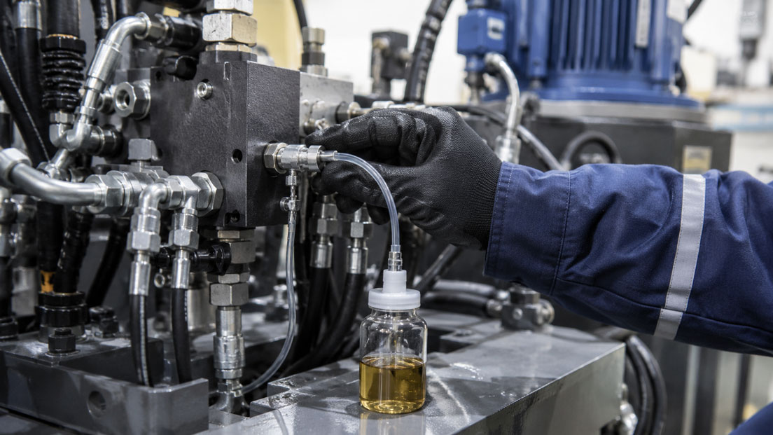
The condition of the hydraulic oil directly affects the reliability of pumps, valves, cylinders and servo components. Solid particles can damage narrow control edges, water can promote corrosion and oil ageing, and metallic wear particles may indicate the onset of component damage.
However, a laboratory analysis or particle count is only as meaningful as the oil sample taken. If the sample is collected from a contaminated drip tray, through the tank opening or from an undefined dead space, the result may not represent the actual condition of the circulating hydraulic oil.
A permanently installed MINIMESS® measuring point enables repeatable sampling from a defined section of the hydraulic circuit. The system generally does not need to be opened for this purpose. However, the selection of the sampling point, flushing of the coupling and hose, use of a clean sample container and consistent documentation of the operating conditions remain essential.
Table of Contents
- Why is a representative oil sample important?
- What information does a hydraulic oil analysis provide?
- Selecting the correct sampling point
- Sampling during operation
- How does sampling via MINIMESS work?
- Correctly accounting for flushing volume and dead volume
- Handling the sample bottle and hose cleanly
- Taking a hydraulic oil sample systematically
- Assessing particle contamination and cleanliness class
- Detecting water in hydraulic oil
- Assessing oil ageing and changes in viscosity
- Correctly interpreting wear particles
- Why trend analyses are more important than individual results
- Typical oil-sampling errors
- Safety when sampling under pressure
- Practical example on a hydraulic press
- Correctly designing the sampling system
- Which products are suitable?
- Conclusion
- Frequently asked questions
Why is a representative oil sample important?
An oil sample represents only a very small portion of the total fluid volume in a hydraulic system. Nevertheless, it is expected to reflect the condition of several tens or several hundreds of litres of hydraulic oil.
For this to be achieved, the sample must have as nearly as possible the same composition as the oil flowing through pumps, valves and actuators during normal operation. This applies in particular to:
- solid particles,
- metallic wear debris,
- water and other liquids,
- oil-ageing products,
- additives and possible foreign oils.
In a stationary system, heavy particles may settle at the bottom of the tank while lighter contaminants remain near the surface. A sample taken immediately after a long shutdown may therefore differ significantly from a sample taken under normal load.
The sampling location also affects the result. A sample taken downstream of a fine filter is more likely to represent the oil cleanliness supplied to sensitive components. A sample upstream of the filter, by contrast, may show which particles are returning from the system and the contamination load that the filter must retain.
Before establishing a sampling programme, the technical question to be answered by the analysis must therefore be defined.
What information does a hydraulic oil analysis provide?
| Analysis value | Possible conclusion | Important note |
|---|---|---|
| Particle count / cleanliness class | Contamination by solid particles | The result is particularly sensitive to contaminated bottles and sampling hoses |
| Water content | Ingress of moisture, condensation, cooler leakage or sealing problems | Dissolved and free water must be distinguished |
| Viscosity | Oil ageing, mixing or thermal damage | Compare with the target value and fresh oil |
| Acid number and oxidation | Chemical ageing of the oil | Limit values depend on the oil type and manufacturer |
| Element analysis | Very fine wear metals, additives and foreign substances | Large wear particles are not fully detected by every method |
| Patch analysis or microscopy | Particle shape, colour and type | Can help distinguish metallic wear, fibres, rust and seal residues |
| Odour and appearance | Initial indications of overheating, foreign oil or severe contamination | Does not replace a quantitative analysis |
A single test method cannot detect every fault. Particle counting, water determination, viscosity measurement and wear analysis are therefore often combined for a comprehensive condition assessment.
Selecting the correct sampling point
The best sampling point depends on the diagnostic objective. Ideally, it is located in a flowing line where the oil and the particles it contains are sufficiently mixed.
| Sampling point | Suitable for | Possible limitation |
|---|---|---|
| Pressure line downstream of the pump | Pump condition and oil cleanliness in the pressure circuit | High pressure requires controlled pressure reduction during sampling |
| Downstream of the pressure filter | Cleanliness of the oil reaching sensitive components | Wear particles upstream of the filter are not fully represented |
| Return line upstream of the filter | Overall wear from valves, cylinders and consumers | The result may depend on individual machine movements |
| Directly downstream of a suspected component | Targeted root-cause analysis | Does not automatically represent the condition of the entire system |
| Return line downstream of the filter | Filter performance and return-line cleanliness | Less suitable for detecting generated wear |
| Tank or drain point | Tank deposits, free water or general reservoir monitoring | Often not representative of the circulating oil |
The same sampling point should always be used for regular trend analyses. Simply changing from a pressure-line sample to a tank sample may alter the particle count so significantly that the results can no longer be compared meaningfully.
Wherever possible, a sampling point should not be located at the end of a long, unflushed branch line. Oil trapped there may remain stationary for a long time and may have a different condition from the main flow.
Sampling during operation
A sample taken under representative operating conditions generally reflects the actual condition of the system better than a sample taken from a cold machine that has been stationary for a long period.
Before sampling, the system should have been operated for a sufficient period so that:
- the normal operating temperature has approximately been reached,
- the oil is circulating through the system,
- particles and water are distributed within the fluid,
- typical pump, valve and cylinder movements have taken place.
Wherever possible, the sample should always be taken under a comparable operating condition. For a machine with strongly varying loads, it must be documented whether the sample was taken during idling, production, full load or immediately after a specific operating cycle.
A sample taken directly after a filter change, oil change or repair may be useful, but it is not directly comparable with a normal trend sample. The special operating condition must be noted in the analysis record.
How does sampling via MINIMESS work?
A MINIMESS® test coupling provides a permanently installed access point to the hydraulic system. When no connector is attached, a non-return mechanism closes the measuring point. Connecting a suitable coupling piece opens the access point in a controlled manner.
For oil sampling, a suitable microbore hose is normally connected to the measuring point. The other end of the hose leads to a controlled sampling device or the sample container.
The advantages of a permanently installed measuring point include:
- repeatable sampling location,
- sampling without opening the hydraulic tank,
- reduced contact between the oil and the surrounding environment,
- controlled discharge of the medium,
- possible sampling during operation,
- use of the same measuring point for additional diagnostic tasks.
However, the test coupling alone does not automatically reduce the system pressure to a value that is safe for an open sample bottle. When sampling from a high-pressure line, the hose, coupling and, where applicable, a restrictor or sampling device must be suitable for the maximum pressure.
A high-pressure jet of oil must never be directed straight into an open bottle.
Correctly accounting for flushing volume and dead volume
Before the actual sample is taken, old oil must be displaced from the test coupling, adapter, hose and any branch lines. Otherwise, the sample will contain a significant proportion of oil that does not originate from the current main flow.
The required flushing volume is not the same for every system. It depends on:
- the internal diameter and length of the hose,
- the volume of the test coupling and adapters,
- the length of an upstream branch line,
- the viscosity and temperature of the oil,
- the required analysis accuracy,
- the previous use of the hose.
The geometric hose volume can be calculated approximately as follows:
Hose volume = π × internal diameter² / 4 × hose length
| Hose | Geometric volume for a length of 1 m |
|---|---|
| DN2 with an internal diameter of approximately 2 mm | approximately 3.1 ml |
| DN4 with an internal diameter of approximately 4 mm | approximately 12.6 ml |
These values do not yet include the volume of the measuring point, adapter and branch line. The entire dead volume must be displaced several times during flushing. The specific flushing quantity should be defined in an operating sampling procedure.
The flushing oil is collected separately and must not enter the sample container. After sufficient flushing, the flow is controlled and the actual sample is taken.
Handling the sample bottle and hose cleanly
During a particle analysis, even a few grains of dust from the surrounding environment can significantly affect the result. The sample container must therefore be suitable for the intended analysis and sufficiently clean.
Important rules include:
- use sample bottles supplied by the laboratory wherever possible,
- open the bottle only immediately before filling,
- do not touch the inside of the bottle or cap,
- do not place the cap on a workbench or machine,
- do not allow the hose end to touch hands, cleaning cloths or the container rim,
- close the bottle immediately after filling,
- do not transfer the sample into another container afterwards.
A certified clean sample bottle should be pre-rinsed with process oil only if the laboratory expressly specifies this procedure. Unauthorised rinsing may impair the defined cleanliness of the container.
The required fill level depends on the analysis. Some methods require a small air space so that the sample can be homogenised before testing. The instructions provided by the commissioned laboratory are decisive.
Taking a hydraulic oil sample systematically
- Define the analysis objective: Determine whether system cleanliness, component wear, water, oil ageing or filter performance is to be assessed.
- Identify the measuring point: Clearly label the sampling point with the system, circuit and position.
- Establish the operating condition: Operate the system under a documented and representative condition.
- Check the equipment: Verify the pressure and temperature rating of the MINIMESS coupling, hose and sampling device.
- Clean the measuring point: Clean the protective cap and surrounding area without introducing dirt into the coupling.
- Connect the hose: Connect the coupling correctly and fully, and secure the hose.
- Flush: Discharge the dead volume and any stagnant oil into a separate container.
- Take the sample: Direct a steady, controlled oil flow into the clean sample bottle.
- Close the bottle: Fit the cap immediately and remove any external oil residues.
- Disconnect the measuring point: Relieve the pressure in the downstream hose section in a controlled manner and disconnect it in accordance with the manufacturer’s instructions.
- Label the sample: Document the system, measuring point, date, operating hours, oil temperature and operating condition.
For recurring analyses, this procedure should be documented as a fixed work instruction. This makes it easier to compare results obtained by different technicians and at different sampling times.
Assessing particle contamination and cleanliness class
The particle contamination of hydraulic fluids is frequently specified as a cleanliness code according to ISO 4406. Three code numbers describe the quantity of particles above defined size classes.
The cleanliness code must be compared with the requirements of the most sensitive components. Servo valves and highly dynamic proportional valves generally require cleaner oil than simple cylinders or low-pressure circuits.
An increased particle value may be caused by:
- insufficient filtration,
- saturated or damaged filter elements,
- wear of pumps and valves,
- assembly contamination introduced into the system,
- contaminated fresh oil,
- an open tank breather or defective breather filter,
- unsuitable sampling.
A single high result should initially be confirmed by a second sample taken correctly. If cleaning or a filter change is initiated immediately without excluding a sampling error, the actual cause may remain undetected.
Detecting water in hydraulic oil
Water may occur in hydraulic oil in dissolved, emulsified or free form. The amount of water that an oil can retain in dissolved form depends, among other factors, on the oil type and temperature.
Possible sources include:
- condensation in the tank,
- leaking water-to-oil heat exchangers,
- cleaning processes,
- humid ambient air,
- unsuitable storage and filling,
- defective seals.
A milky or cloudy sample may indicate emulsified water. However, clear oil is not proof that the water content is acceptable. Dissolved water is often not visually detectable.
The laboratory may specify the water content in ppm or as relative saturation, for example. The oil type, operating temperature and specifications of the system or oil manufacturer must be considered during assessment.
Assessing oil ageing and changes in viscosity
Hydraulic oil ages due to temperature, oxygen, pressure stress and catalytically active wear metals. This can alter the viscosity, acid number, colour and additive concentration.
Excessive viscosity can cause increased pressure losses, poor cold-start behaviour and sluggish valve operation. Insufficient viscosity can reduce the lubricating film and increase internal leakage.
Deviations may also result from mixing with:
- hydraulic oil of a different viscosity grade,
- gear or lubricating oil,
- fuel,
- cleaning fluid,
- water-glycol fluid.
A condition analysis should therefore be compared wherever possible with a reference sample of the fresh oil used and with the manufacturer’s data.
Correctly interpreting wear particles
Metallic particles may provide indications of the origin of damage. Iron may originate, for example, from gears, bearings or cylinder surfaces. Copper may indicate bearing bushes or certain cooler materials. Chromium and nickel may originate from coated or alloyed components.
However, the allocation is not always unambiguous. The following are decisive:
- the material composition of the system,
- particle size and shape,
- concentration and development over time,
- accompanying pressure, temperature and vibration values,
- repairs or component replacements that have been carried out.
Very fine wear metals can be detected by element analysis. Larger metallic particles can often be assessed more effectively using patch analysis, microscopy, ferrographic methods or a suitable ferromagnetic index.
An increase in the iron value without any change in the particle count may therefore have a different significance from a simultaneous increase in metal concentration, coarse particles and pump noise.
Why trend analyses are more important than individual results
The most important advantage of regular oil sampling lies in monitoring changes over time. A value that still appears acceptable for one machine may be critical if it deteriorates significantly within only a few weeks.
For comparable trend data, the following should remain constant:
- sampling point,
- sampling hose and procedure,
- operating condition and oil temperature,
- laboratory and analysis method,
- sampling interval,
- documentation of modifications to the system.
Filter changes, top-up quantities, repairs, oil changes and unusual operating events should also be documented. Otherwise, an improvement or deterioration in the analysis results may be interpreted incorrectly.
Typical oil-sampling errors
Sampling through the open top of the tank
Dust from the surrounding environment can enter the bottle. In addition, the sampling depth is often not reproducible.
Sampling directly from the tank drain
The sample may contain sediment and free water from the bottom of the tank and may not represent the circulating oil.
The measuring hose is not flushed
Old oil and deposits from the hose distort the result.
Using any drinks bottle as a sample container
Residues, dust and cleaning agents may render particle, water and chemical analyses unusable.
Sampling from a cold, stationary system
Settled particles and unevenly distributed water are not recorded representatively.
Comparing different sampling points
The apparent trend is caused by the changed location rather than by a change in the oil condition.
The hose end touches the bottle rim
External contamination may enter the sample directly.
The oil sample is left open
Dust, moisture and possible evaporation alter the sample before analysis.
The flushing oil is used as the sample
It contains an excessive proportion of oil from the dead space, test coupling and hose.
Safety when sampling under pressure
Hydraulic oil under high pressure can cause severe injuries. Even a very fine jet can penetrate the skin. Hot surfaces and high oil temperatures create additional hazards.
The following must therefore be checked before sampling:
- maximum operating pressure and possible pressure peaks,
- permissible pressure of the test coupling, hose and adapters,
- media and temperature resistance of the seals,
- secure attachment and routing of the hose,
- controlled pressure reduction before the open sample container,
- suitable personal protective equipment,
- a secure collecting container for the flushing oil.
Leaks must never be searched for by hand. Before disconnection, it must be ensured that the downstream section of hose has been depressurised in a controlled manner.
Sampling may only be carried out by trained personnel in accordance with the operating and safety instructions for the system.
Practical example: Monitoring oil condition on a hydraulic press
A proportional valve on a hydraulic press repeatedly develops faults. The system has a pressure filter downstream of the pump and a return filter upstream of the tank.
Two permanent MINIMESS® sampling points are used for diagnosis:
- downstream of the pressure filter to assess oil cleanliness upstream of the valves,
- in the return line upstream of the filter to detect wear returning from the system.
The samples are taken after one hour of production operation at a comparable oil temperature. The test coupling and hose are flushed completely in each case. The particle count, water content, viscosity and wear metals are then analysed.
The sample downstream of the pressure filter initially complies with the required cleanliness class. However, the particle count in the return line is significantly higher, and the iron content has increased compared with previous samples.
An additional microscopic examination reveals metallic cutting and fatigue particles. Further inspection identifies the onset of wear in the hydraulic pump. The pressure filter retains a large proportion of the particles, which is why the oil cleanliness upstream of the valve still appears normal.
After the pump is replaced and the system is flushed in a controlled manner, the particle count and iron value decrease. Repeatable sampling at two defined measuring points therefore enables both root-cause analysis and verification of the corrective action.
Correctly designing the sampling system
At least the following information is required for selection and positioning:
- hydraulic medium and viscosity grade,
- minimum and maximum operating pressure,
- oil and ambient temperature,
- required sampling point in the circuit,
- analysis objective and required sample volume,
- available process connection,
- required hose length,
- material and sealing requirements,
- possible pressure peaks,
- required pressure reduction,
- mobile or permanently installed sampling device.
The measuring point should ideally be included during the design of the hydraulic system. Sampling points added retrospectively at difficult-to-access or unrepresentative locations make regular condition monitoring more difficult.
Which products are suitable?
MINIMESS couplings and hoses
The MINIMESS couplings and hoses category includes test couplings, microbore hoses and accessories for diagnostic, measurement and service tasks on hydraulic systems.
For oil sampling, the test coupling, hose, adapter and, where necessary, a device for controlled pressure reduction are selected to suit the maximum system pressure and hydraulic medium.
MINIMESS from Hydrotechnik
The MINIMESS from Hydrotechnik category includes original Hydrotechnik system access points for measurement, diagnostics, filling, venting and sampling.
A permanently installed measuring point creates a reproducible sampling location and reduces the need to open the tank or a hydraulic line for every sample.
MINIMESS® 1620
The MINIMESS® 1620 is a compact system access point for hydraulic and fluid circuits. It can be used for pressure measurement, venting, filling and sampling, among other tasks.
The series is available with different process threads, materials and sealing options. For oil sampling, the process connection, seal, operating pressure and oil temperature must be selected to suit the system.
MINIMESS hoses
The MINIMESS hoses category includes microbore hoses for measurement and service applications.
For sampling, the hose should be selected as short as practically possible. A small internal diameter reduces the dead and flushing volume. At the same time, the permissible pressure, temperature, bending radius and media compatibility must be observed.
Conclusion: A reliable oil analysis begins at the sampling point
A laboratory analysis can provide reliable information about particles, water, oil ageing and wear only if the oil sample represents the actual condition of the system.
A permanently installed MINIMESS® measuring point enables repeatable sampling from a defined section of the hydraulic circuit. This avoids open tank samples and changing sampling locations.
Before the actual sample is taken, the test coupling, branch line and hose must be flushed sufficiently. The sample must then be filled into a clean, suitable container and closed immediately.
For condition monitoring, recurring samples taken under comparable operating conditions are more important than an individual result. Only the trend in cleanliness class, water, viscosity and wear-metal concentration shows whether the system condition is changing.
The measuring point, MINIMESS coupling, hose, pressure-reduction device and sample container must therefore be considered as one complete sampling system.
Frequently asked questions about MINIMESS sampling
Can a hydraulic oil sample be taken while the system is operating?
Sampling during operation is possible with a suitable MINIMESS system access point. The coupling, hose and sampling device must be designed for the pressure, temperature and medium.
Where should the oil sample be taken?
The sampling point depends on the diagnostic objective. The return line upstream of the filter is often suitable for evaluating overall wear. A measuring point downstream of the pressure filter provides more useful information about the oil cleanliness at sensitive components.
Why must the MINIMESS hose be flushed?
The hose and coupling contain stagnant oil from previous use or from the dead volume. Without flushing, this oil enters the sample and distorts the result.
How much oil must be flushed before sampling?
The entire dead volume of the measuring point, adapter, branch line and hose must be displaced several times. There is no universal flushing quantity; it should be defined for the specific measuring point.
Can the sample be taken directly from the tank?
A tank sample may be useful for certain questions but is often less reproducible. Deposits, sampling depth and system shutdown can significantly influence the result.
Which bottle is suitable for particle analysis?
A suitable, sufficiently clean sample bottle should be used, preferably one supplied by the commissioned laboratory. Ordinary drinks bottles are unsuitable for reliable particle analysis.
Why are regular samples better than a single analysis?
Regular samples show the development over time. This enables increasing particle counts, rising water content or growing concentrations of wear metals to be detected at an early stage.
Which information does ICS Schneider require for the configuration?
The required information includes the hydraulic medium, operating pressure, temperature, process connection, required sampling point, hose length, analysis objective, required sample volume, and material and sealing requirements.