


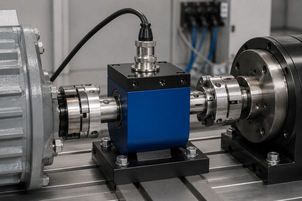
The mechanical power of a motor, gearbox, pump or driven machine cannot be determined from torque or rotational speed alone. Only the time-synchronised measurement of both variables shows how much power is actually being transmitted through a shaft.
High torque at a low rotational speed can produce the same power as considerably lower torque at a high rotational speed. For efficiency measurements, characteristic-curve tests, endurance testing and dynamic load changes, torque and speed must therefore be measured simultaneously, scaled correctly and processed using a common time base.
The calculation itself is straightforward. However, the quality of the result depends on the complete measuring chain: torque sensor, speed sensor, mechanical coupling, signal conditioning, sampling rate, synchronisation, test-bench software and calibration must all be compatible.
Table of Contents
- How is mechanical power calculated?
- Calculation example using torque and speed
- Why must both measured variables be recorded simultaneously?
- Measuring torque in a rotating drive train
- Measuring rotational speed reliably
- Pulses per revolution and speed resolution
- Position of the sensors on the test bench
- Alignment, couplings and unwanted forces
- Selecting the correct torque measuring range
- Synchronisation and a common time base
- Defining the sampling rate and bandwidth
- Dynamic power during load changes
- Direction of rotation, torque sign and generator operation
- Scaling signals correctly
- Measurement uncertainty of the power calculation
- Determining the efficiency of motors and gearboxes
- Data acquisition and test-bench software
- Typical measurement and calculation errors
- Practical example on a gearbox test bench
- Selecting the measuring chain for the test bench
- Which measuring instruments and products are suitable?
- Conclusion
- Frequently asked questions
How is mechanical power calculated?
For a rotating shaft, mechanical power is calculated from torque and angular velocity:
P = M × ω
Where:
- P = mechanical power in watts,
- M = torque in newton metres,
- ω = angular velocity in radians per second.
On test benches, rotational speed is usually stated in revolutions per minute. The angular velocity is then calculated as follows:
ω = 2 × π × n / 60
For practical calculations, the following relationship can be used directly:
P [kW] = M [Nm] × n [min⁻¹] / 9,550
The commonly used value 9,550 is a rounded conversion factor. It accounts for the conversion from revolutions per minute to radians per second and from watts to kilowatts.
| Required variable | Calculation |
|---|---|
| Power in kW | P = M × n / 9,550 |
| Torque in Nm | M = P × 9,550 / n |
| Rotational speed in min⁻¹ | n = P × 9,550 / M |
These formulae apply to mechanical shaft power. Electrical input power, hydraulic power and thermal losses are not automatically included.
Calculation example using torque and speed
The following values are measured on a motor test bench:
- Torque: 120 Nm,
- Rotational speed: 1,500 min⁻¹.
The mechanical power is:
P = 120 Nm × 1,500 min⁻¹ / 9,550 = 18.85 kW
If the speed rises to 3,000 min⁻¹ while the torque remains the same, the power doubles to approximately 37.7 kW.
If the torque falls to 60 Nm at 3,000 min⁻¹, the power is again approximately 18.85 kW. This example shows why neither torque nor rotational speed alone provides information about the mechanical power being transmitted.
Why must both measured variables be recorded simultaneously?
At a steady operating point with almost constant torque and rotational speed, the power can be approximated from two values read one after the other. This method is insufficient during load changes, start-up processes or with pulsating drives.
The instantaneous power is:
P(t) = M(t) × ω(t)
Torque and rotational speed must therefore refer to the same point in time. If the torque is measured a few milliseconds earlier or later than the corresponding speed, an incorrect power curve can result during rapid processes.
Calculating separate average values can also cause errors:
The average of M × n is not necessarily equal to the average of M multiplied by the average of n.
If torque and speed fluctuate simultaneously, the power must first be calculated for every measurement point. The resulting power curve can then be averaged or integrated.
Measuring torque in a rotating drive train
To measure transmitted shaft power directly, a rotating torque sensor is often installed between the drive and the loading machine. The sensor’s measuring body twists slightly under the transmitted torque.
Strain gauges attached to the measuring body detect this torsion. A Wheatstone bridge circuit converts the strain into an electrical signal. This signal is then transferred from the rotating shaft to the stationary evaluation system using slip rings, inductive transmission or telemetry.
Rotating sensors are suitable for applications such as:
- motor and gearbox test benches,
- pump and compressor testing,
- friction measurements on bearings and gearboxes,
- tool and spindle test benches,
- endurance and service-life testing,
- analysis of start-up and load-change processes.
Alternatively, a reaction torque sensor can measure the supported torque on a stationary housing. However, this method is suitable only if all reaction forces are transmitted completely and unambiguously through the sensor.
Measuring rotational speed reliably
Speed measurement may be integrated directly into the torque sensor or performed using a separate speed sensor. A separate sensor is required if the torque transducer has no suitable speed output or if an independent reference measurement is required.
Typical measuring principles include:
| Measuring principle | Detected target | Typical strength |
|---|---|---|
| Optical reflective sensor | Reflective mark on a shaft or coupling | Non-contact measurement and independent of the shaft material |
| Inductive sensor | Metal teeth or a toothed wheel | Robust against oil, dirt and industrial conditions |
| Hall-effect or magnetic sensor | Magnet or magnetised structure | Reliable even at low speeds |
| Incremental encoder | Code disc with several tracks | High resolution and possible direction detection |
| Handheld tachometer | Reflective mark or mechanical contact | Well suited to verification and commissioning |
For continuous power calculation, a permanently installed sensor with a frequency, pulse or digital signal that can be recorded directly should be used. A portable tachometer is primarily suitable for comparative measurements and checking individual operating points.
Pulses per revolution and speed resolution
A speed sensor often provides a defined number of pulses per shaft revolution. The rotational speed is calculated from the signal frequency:
n [min⁻¹] = 60 × f [Hz] / z
Here, z is the number of detected teeth, marks or pulses per revolution.
Example:
- Gear wheel with 60 teeth,
- Measured frequency of 1,500 Hz.
The resulting rotational speed is:
n = 60 × 1,500 / 60 = 1,500 min⁻¹
A high pulse count improves temporal resolution at low rotational speeds. At the same time, the signal frequency rises at high speeds. The maximum input frequency of the sensor and measuring instrument must not be exceeded.
With only one reflective mark per revolution, a speed of 60 min⁻¹ generates just one pulse per second. Rapid speed changes can therefore be detected only to a limited extent. A toothed wheel or incremental encoder with several pulses per revolution may be considerably more suitable for dynamic testing.
Position of the sensors on the test bench
The torque sensor always measures the torque at its actual installation position. If additional bearings, couplings, belts or gearbox stages are located between the sensor and the test object, their losses may affect the result.
Typical test-bench arrangements are:
Drive → coupling → torque sensor → coupling → test object → loading machine
or:
Drive → test object → torque sensor → loading machine
Two measuring points are often required to determine gearbox efficiency:
- Torque and rotational speed at the gearbox input,
- Torque and rotational speed at the gearbox output.
Only then can the input and output power be compared directly. If only one shaft power is measured, the losses of the remaining components must be determined or accounted for separately.
Alignment, couplings and unwanted forces
A torque sensor is designed for torsional loading. Axial forces, radial forces and bending moments can influence the measured value or mechanically damage the transducer.
The following points are therefore particularly important during installation:
- coaxial alignment of the drive, sensor and loading machine,
- suitable flexible couplings,
- defined axial distances,
- backlash-free or otherwise application-appropriate shaft connections,
- secure mounting of the sensor housing,
- compliance with the permissible rotational speed,
- protection against overload and torque peaks,
- a suitable guard for rotating parts.
Flexible couplings can compensate for limited angular, parallel and axial misalignment. However, they must not be used to compensate for major alignment errors in the test bench.
At high rotational speeds, imbalance, critical speed, coupling mass and possible torsional resonances must also be considered. The entire shaft train must be assessed mechanically, not just the sensor.
Selecting the correct torque measuring range
The rated measuring range should cover the normal operating range effectively while providing sufficient reserve for starting torque and load peaks.
An unnecessarily large measuring range reduces the usable accuracy at low torque values. If the error limit is specified as a percentage of full scale, the absolute error remains the same regardless of the current measured value.
Example for a sensor with a 500 Nm full scale and an error limit of 0.1 % of full scale:
- Absolute error component: 0.5 Nm,
- At 500 Nm: 0.1 % of the measured value,
- At 50 Nm: 1 % of the measured value,
- At 10 Nm: 5 % of the measured value.
A sensor should therefore not be selected solely according to the highest conceivable fault torque. For extreme peaks, a mechanical overload coupling, torque limiter or separate protective device may be appropriate.
The operating torque, limit torque, breaking torque and permissible alternating load must also be considered. A briefly permissible overload torque is not automatically approved for frequently recurring load changes.
Synchronisation and a common time base
For instantaneous power calculation, the torque and speed channels must share a common time base. The most reliable method is to record both signals simultaneously using the same multichannel measuring instrument.
If separate measuring instruments are used, the following are required as a minimum:
- a common trigger signal,
- known and stable timestamps,
- known channel delays,
- identical or subsequently comparable sampling rates,
- controlled merging of the data.
Different filter settings may also cause a phase shift. A heavily smoothed speed signal may lag behind a faster torque signal. Multiplying the two values can then produce incorrect short-term power values.
Defining the sampling rate and bandwidth
The required sampling rate depends not only on the rotational speed but also on the fastest change that must be evaluated on the test bench.
A relatively low recording rate may be sufficient for a stable operating point. Considerably higher rates are required for:
- starting and braking,
- gear changes,
- torque peaks,
- combustion engines with cyclic torque,
- electric drives with rapid control response,
- cogging torque and torsional vibration.
The sampling rate must be higher than the highest signal frequency of interest. In practice, a significant reserve above the basic Nyquist limit is often used. The sensor bandwidth, signal filters and anti-aliasing must also match the sampling rate.
A high sampling rate alone does not improve the measurement if the torque sensor or signal conditioning already strongly attenuates rapid processes.
Dynamic power during load changes
For dynamic testing, the power is calculated for every measurement point:
Pi = Mi × 2 × π × ni / 60
The power curve can then be used to determine:
- instantaneous peak power,
- average power during a test cycle,
- transmitted mechanical energy,
- power during acceleration and deceleration,
- frequency of load changes,
- deviations between target and actual characteristic curves.
The mechanical energy is obtained by integrating the power over time:
E = ∫ P(t) dt
When a rotating mass is accelerated, part of the power is not delivered to the actual test object but is used to change the rotational energy. An inertia correction may therefore be required for highly dynamic test benches.
Direction of rotation, torque sign and generator operation
When calculating only positive power values, the magnitudes of torque and rotational speed are often used. However, this removes information about the direction of energy flow.
A clear sign convention could define, for example:
- positive speed = defined primary direction of rotation,
- positive torque = driving torque in this direction,
- positive power = motor operation,
- negative power = braking or generator operation.
The power becomes negative only when the torque and angular velocity have opposite signs. This occurs, for example, during regenerative operation or when a loading machine absorbs energy from the drive train.
When the direction of rotation changes, both the speed signal and torque signal must be processed with the correct sign. A simple single-channel speed sensor often provides only the magnitude of the rotational speed. A second signal track or separate direction signal may be required to detect the direction.
Scaling signals correctly
Torque and speed sensors may provide different electrical output signals:
- mV/V bridge signal,
- 0–10 V or ±10 V,
- 4–20 mA or centred current signals with direction encoding,
- frequency or pulses,
- TTL, HTL or push-pull signal,
- CAN, CANopen or other digital interfaces.
The zero point, full-scale value, unit and sign must be entered correctly in the data-acquisition system. For a frequency signal, the number of pulses per revolution is also required.
Typical scaling information includes:
| Channel | Required information |
|---|---|
| Torque | Electrical zero point, positive and negative full-scale value, unit Nm |
| Rotational speed | Pulses per revolution, frequency range, direction evaluation |
| Power | Formula, unit conversion and sign convention |
Confusing min⁻¹ with s⁻¹ causes an error by a factor of 60. If the power is required in kilowatts, the conversion from watts to kilowatts must also be included.
Measurement uncertainty of the power calculation
The uncertainty of the power depends at least on the uncertainties of the torque and rotational-speed measurements. For independent relative uncertainties, the following approximation can be used:
uP,rel ≈ √(uM,rel² + un,rel²)
Additional influences may include:
- zero-point drift of the torque sensor,
- temperature changes,
- hysteresis and repeatability,
- transverse forces and bending moments,
- pulse resolution of the speed measurement,
- synchronisation and filter delay,
- digital rounding and scaling,
- calibration uncertainty.
At very low torque, the relative power uncertainty can increase considerably even though the absolute sensor accuracy remains unchanged. A test report should therefore not state only a general percentage but should take account of the actual load and speed range used.
Determining the efficiency of motors and gearboxes
For a gearbox test bench, mechanical efficiency is calculated from the input and output power:
η = Pout / Pin × 100 %
Example:
- Input power: 25.0 kW,
- Output power: 23.5 kW.
The efficiency is:
η = 23.5 / 25.0 × 100 % = 94 %
For this calculation, torque and rotational speed must be measured on both sides if the speed changes due to the transmission ratio.
For an electric motor, the mechanical output power can be compared with the electrical input power. The electrical power must be measured using a suitable power analyser that accounts for the power factor, harmonics and, where applicable, a multiphase supply.
Measured values from different test instruments must be time-synchronised. A common trigger or synchronised acquisition is particularly important for load profiles.
Data acquisition and test-bench software
A suitable multichannel measuring system should record the torque and speed signals simultaneously and provide the mechanical power directly as a calculated channel.
Important functions include:
- a common time base for all channels,
- analogue and frequency inputs,
- sufficient sampling speed,
- freely configurable sensor scaling,
- mathematical calculation channels,
- triggering based on speed, torque or external events,
- recording of raw data,
- export for further analysis,
- graphical display of characteristic curves,
- documentation of sensor and calibration data.
For a motor or pump characteristic curve, rotational speed, torque, power, pressure, flow and temperature can all be recorded together. This enables mechanical, hydraulic and thermal relationships to be evaluated within the same test cycle.
The raw signals should be stored at least for critical tests. If only the calculated power curve is saved, it is difficult to determine later whether an unusual value was caused by the torque, speed or calculation channel.
Typical measurement and calculation errors
Torque and rotational speed are read one after the other
Under fluctuating load, the two values do not belong to the same operating condition. The calculated power is not representative.
Average values are calculated before multiplication
For dynamic signals, the product of the averages may differ from the average of the actual power.
The torque sensor is significantly oversized
Normal test operation uses only a small part of the measuring range. The relative uncertainty increases accordingly.
The rotational speed is calculated using the wrong pulse count
A toothed wheel may have 60 teeth, while the software is configured for one pulse per revolution. The displayed speed is incorrect by a factor of 60.
Revolutions per second are treated as min⁻¹
The calculated power differs by a factor of 60.
The sensors use different filter times
The torque and speed curves are shifted relative to one another. Incorrect power peaks occur during rapid load changes.
Transverse forces act on the torque sensor
Poor alignment or unsuitable couplings place additional loads on the sensor and may affect its zero point or characteristic curve.
The sign is not taken into account
Generator or braking operation is incorrectly displayed as positive driving power.
The rotational speed is measured at a different gearbox stage
Torque and speed do not refer to the same shaft. The power calculation is incorrect unless the transmission ratio is taken into account.
Only the calculated power is stored
Subsequent root-cause analysis is not possible because the raw torque and speed values are unavailable.
Practical example: Power and efficiency on a gearbox test bench
A reduction gearbox is to be tested at different rotational speeds and loads. An electric motor is installed at the input and a controllable loading machine at the output.
The test bench is equipped with the following measuring points:
- rotating torque sensor and speed sensor at the gearbox input,
- a second torque sensor and speed sensor at the gearbox output,
- temperature sensor in the gearbox oil,
- multichannel measuring instrument with common calculation channels.
The following values are measured at one operating point:
| Measured variable | Input | Output |
|---|---|---|
| Rotational speed | 3,000 min⁻¹ | 750 min⁻¹ |
| Torque | 80 Nm | 300 Nm |
The input power is:
Pin = 80 × 3,000 / 9,550 = 25.13 kW
The output power is:
Pout = 300 × 750 / 9,550 = 23.56 kW
This results in a mechanical efficiency of:
η = 23.56 / 25.13 × 100 % = 93.8 %
During a rapid load step, the evaluation initially shows a brief efficiency of more than 100 %. The raw data reveal that the output speed channel is smoothed considerably more heavily than the corresponding torque channel.
After matching the filter times and recalculating the data synchronously, the unrealistic power peak disappears. This example shows that a mathematically correct formula does not guarantee a correct power result if the input signals are not time-synchronised.
Selecting the measuring chain for the test bench
At least the following information is required for system design:
- minimum, normal and maximum torque range,
- maximum rotational speed and direction of rotation,
- static or dynamic measuring task,
- expected torque and load peaks,
- required accuracy and bandwidth,
- shaft diameter and mechanical connections,
- permissible axial and radial loads,
- available installation space,
- ambient temperature, contamination and degree of protection,
- target geometry for rotational-speed measurement,
- pulses per revolution and maximum frequency,
- required output signals,
- number of additional measuring channels,
- sampling rate, recording duration and trigger conditions,
- calibration and documentation requirements.
The torque sensor, couplings and speed measurement should be designed together with the data-acquisition system. A mechanically suitable measuring shaft is useful only if its speed limit, signal format and dynamic behaviour also match the testing task.
Which measuring instruments and products are suitable?
Torque sensors
The torque sensors category includes rotating transducers for machinery, drives and test benches.
The measuring range, maximum rotational speed, mechanical connections, output signal, overload reserves and required measurement dynamics must be defined during selection.
HySense TQ100
The HySense TQ100 is a rotating torque sensor using the strain-gauge measuring principle and slip-ring transmission.
It is available for measuring ranges from 1 to 500 Nm, has a measuring accuracy of 0.1 % of full scale and provides integrated direction detection. The 12 ± 8 mA ISDS output signal is intended for use with compatible Hydrotechnik measuring systems.
Typical applications include constant and alternating torque, friction measurements on gearboxes and bearings, and monitoring of rotating shafts.
HySense TQ110
The HySense TQ110 is also a rotating torque sensor with slip-ring transmission.
It has a 4–20 mA output, an error limit of 0.1 % of full scale and a repeatability of ±0.05 %. Depending on the version, the maximum permissible rotational speed is up to 2,000 min⁻¹.
The sensor is therefore suitable for test benches with comparatively moderate rotational speeds where an industrial current signal is required.
Speed sensors and tachometers
The speed sensors / tachometers category includes optical, inductive and magnetic sensors as well as portable verification instruments.
A permanently installed frequency or pulse sensor should be used for continuous test-bench measurement. Portable instruments are particularly suitable for commissioning and independent plausibility checks.
HySense RS100
The HySense RS100 detects a reflective mark on a rotating component without contact.
It has a response time of 500 µs and can measure rotational speeds up to 30,000 min⁻¹ using one reflective mark. The optical principle is useful when no toothed wheel is available or the shaft material is unsuitable for inductive detection.
HySense RS500 and RS5xx
The HySense RS500 is a robust inductive speed sensor with an active push-pull output.
Its frequency range extends to approximately 10 kHz. It is therefore suitable, for example, for detecting metal teeth or toothed wheels on industrial test benches. The tooth count, rotational speed and maximum input frequency of the measuring instrument must be designed together.
MultiSystem 5070
The MultiSystem 5070 is a portable multichannel measuring instrument for diagnostic and testing tasks.
It provides analogue inputs as well as switchable frequency and current inputs, calculation channels and a sampling rate of up to 10 kHz. Frequency and pulse signals can be recorded up to 20 kHz.
Torque, rotational speed and additional variables such as pressure, temperature or flow can be recorded within the same measurement series. Mechanical power can be generated as a calculation channel from the synchronously recorded values.
Complete sensor range
The displacement, force, speed, torque and vibration sensors category includes additional sensors, signal converters and components for test benches, machinery monitoring and condition monitoring.
This enables additional variables such as force, displacement, pressure, temperature and vibration to be included in the test-bench analysis alongside the mechanical shaft power.
Conclusion: Reliable power calculation requires a coordinated measuring chain
The mechanical power of a rotating shaft is calculated from the product of torque and angular velocity. For torque in newton metres and rotational speed in revolutions per minute, the power in kilowatts can be calculated using the formula P = M × n / 9,550.
During dynamic processes, torque and rotational speed must be recorded simultaneously using a common time base. Separate readings, different filter times or unsynchronised data loggers can cause substantial power errors.
The torque sensor must match the normal load range, maximum rotational speed and mechanical installation conditions. An unnecessarily large measuring range reduces the relative accuracy at low torque values.
For speed measurement, the number of pulses per revolution, maximum signal frequency and measuring time determine the resolution. Several pulses per revolution are often advantageous for dynamic testing.
A reliable test-bench solution therefore comprises more than two sensors. The torque sensor, speed sensor, couplings, signal conditioning, data acquisition, calculation formula and calibration form one complete measuring system.
Frequently asked questions about measuring torque, speed and power
How do I calculate mechanical power from torque and rotational speed?
For torque in Nm and rotational speed in min⁻¹, the following applies: power in kW = torque × rotational speed / 9,550.
Why must torque and rotational speed be measured simultaneously?
Under varying loads, both variables change over time. Only values belonging to the same point in time produce the actual instantaneous power.
Can I calculate average power from average torque and average speed?
For constant operating points, this is approximately possible. For correlated or dynamic fluctuations, the instantaneous power must first be calculated and then averaged.
Where is the torque sensor installed on a test bench?
It is installed within the power flow between the drive, test object and loading machine. Its position determines which losses and components are included in the measured torque.
How many pulses per revolution should the speed sensor provide?
This depends on the speed range and required dynamic response. More pulses improve resolution at low speeds but increase the signal frequency at high speeds.
Why does the test bench briefly show an efficiency above 100 %?
Common causes include unsynchronised measuring channels, different filter times, incorrect scaling or stored rotational energy during dynamic processes.
How do I select the measuring range of the torque sensor?
Normal operation should use a sufficiently large proportion of the measuring range. Starting torque, load peaks, limit torque and alternating loads must also be considered.
Can a handheld tachometer be used for power calculation?
In principle, this is possible for a stable individual operating point. However, a permanently installed and synchronously recorded speed channel is required for continuous or dynamic power calculations.
Which information does ICS Schneider require for system design?
The required information includes the torque and speed range, load peaks, measurement dynamics, mechanical connections, shaft dimensions, installation space, ambient conditions, output signals, required sampling rate, and calibration and documentation requirements.