


A stationary battery system is still operating.
At first glance, the block voltages appear normal.
Does this mean the battery is still in good condition?
Not necessarily.
A single measured parameter can only provide limited information about the condition of a battery.
For a reliable battery diagnosis, different characteristics must be distinguished:
Voltage → electrical operating condition
Internal resistance → changes in the electrical and electrochemical condition
Capacity → actually available energy under defined discharge conditions
Temperature → thermal condition and important influencing factor
Electrolyte density → additional condition indicator for flooded lead-acid batteries
Connector voltage drop → quality of connections under load
The strength of professional battery maintenance therefore lies not in a single measurement, but in combining several test methods and comparing their results over time.
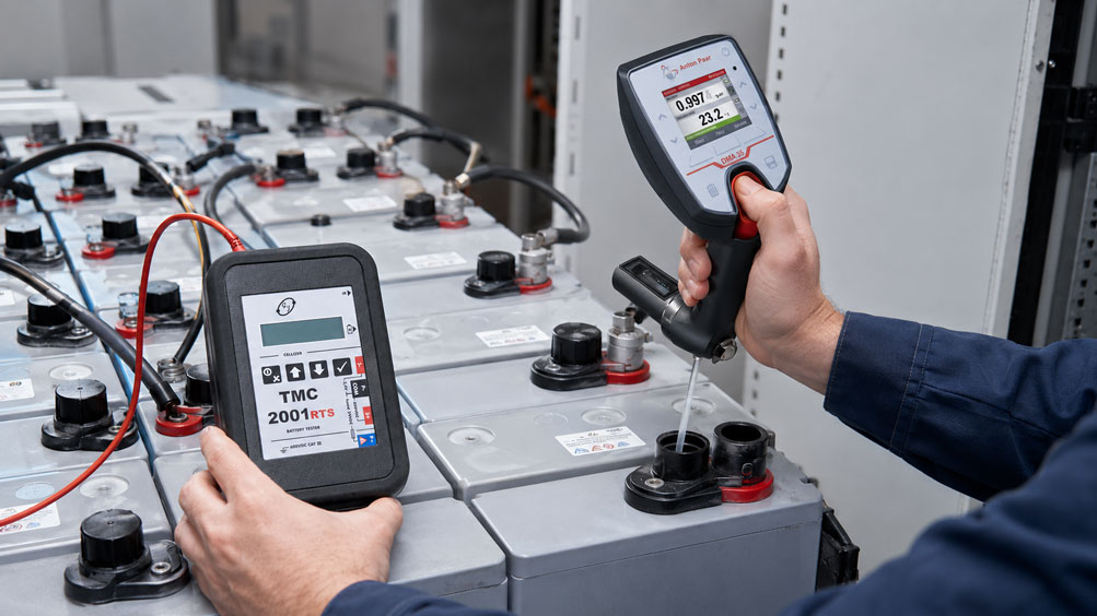
This is exactly what the TMC-2001RTS Battery Tester is designed for.
It combines various test methods within a battery system and enables structured storage and subsequent evaluation of the measured values.
For flooded lead-acid batteries, the diagnosis can additionally be supplemented by electrolyte density measurement. The Anton Paar DMA 35 can be used for this purpose. The recorded density and temperature values can then be assigned to the TMC system and the correct battery installation.
Table of Contents
- Why is a single battery measurement not sufficient?
- Which methods are available for battery testing?
- 1. Visual inspection as the basis
- 2. Measuring block voltage and float-charge voltage
- 3. Measuring internal resistance
- Considering Rel and Rct separately
- Why Kelvin measurement is important
- Why the trend is more important than a single resistance value
- 4. Testing capacity by controlled discharge
- Monitoring block voltages during discharge
- Recording total voltage and discharge current
- 5. Testing battery connectors under load
- 6. Measuring battery temperature
- 7. Measuring electrolyte density in flooded lead-acid batteries
- Determining electrolyte density with the Anton Paar DMA 35
- Transferring measured values from the DMA 35 to the TMC-2001RTS
- Reading out DMA35 V3 via IrDA
- DMA35 V4 and Bluetooth
- What does electrolyte density actually tell you?
- Which tests are suitable for which battery type?
- Which method detects which fault?
- Recommended test procedure for stationary battery systems
- Documenting and comparing measured values
- Typical errors in battery maintenance
- Practical example: systematically testing a UPS battery system
- Suitable ICS products
- Conclusion
- FAQ
Why is a single battery measurement not sufficient?
Batteries are electrochemical systems.
Their condition therefore cannot be fully described by a single electrical measurement.
Voltage example
A battery block can have an apparently correct voltage during float charging.
However, this does not prove that the block will be able to deliver the required capacity during a subsequent discharge.
Internal resistance example
An unusual resistance value can indicate a change in the battery block.
However, the resistance value is not automatically equivalent to:
remaining capacity in Ah
Electrolyte density example
In a flooded lead-acid battery, the electrolyte density provides additional information about the condition of the electrolyte and the state of charge.
However, it does not replace a controlled capacity test either.
Several diagnostic levels should therefore be combined
| Test | Main information provided |
|---|---|
| Visual inspection | Mechanical condition and obvious damage |
| Block voltage | Electrical operating condition and differences between blocks |
| Internal resistance | Changes in battery condition |
| Capacity test | Actually available capacity under defined load conditions |
| Temperature | Thermal abnormalities and comparability of measurements |
| Electrolyte density | Additional diagnosis for flooded lead-acid batteries |
| Connector voltage drop | Condition of electrical connections under load |
Which methods are available for battery testing?
For stationary battery systems, the most important test methods can basically be divided into three groups.
1. Testing during normal operation
These include, for example:
- visual inspection,
- float-charge voltage,
- block voltage,
- temperature,
- internal resistance.
2. Testing under a defined load
These include:
- capacity test,
- discharge curve,
- total voltage,
- discharge current,
- voltage drop across battery connectors.
3. Additional electrochemical testing
For accessible flooded lead-acid batteries, the:
electrolyte density
can additionally be measured.
The methods complement one another
A useful maintenance plan therefore combines:
quick regular condition checks
with:
periodic more detailed testing
1. Visual inspection as the basis
Before connecting test leads, a battery system should first be visually inspected.
Items to check include
- damage to the housing,
- deformation or swelling,
- corrosion on terminals and connectors,
- unusual deposits,
- loose connections,
- leaks,
- unusual heating or discoloration,
- for flooded batteries, also the electrolyte area.
Why is this important?
Electrical measurements cannot completely replace the detection of mechanical defects.
Structured battery maintenance therefore always begins with the overall condition of the system, not just with the first measured value.
2. Measuring block voltage and float-charge voltage
One of the simplest tests is measuring the individual cell or block voltages.
During float charging
the battery is normally permanently connected to the charger.
In this case, not only the absolute voltage is of interest, but above all:
How do the individual blocks differ from one another?
Example
Almost all blocks in a battery system show:
13.55 … 13.62 V
while one block shows:
13.20 V
Such a deviation
should be investigated even if the overall voltage of the battery system initially appears plausible.
TMC-2001RTS – float-charge function
The TMC-2001RTS provides a dedicated function for repeated recording of block voltages during float charging.
This allows, for example:
quarterly comparison measurements
to be systematically assigned to the same battery system.
Important
A correct float-charge voltage primarily shows that the block is currently in a plausible electrical operating condition.
It does not automatically prove sufficient remaining capacity.
3. Measuring internal resistance
Internal resistance measurement is one of the most important methods for recurring condition diagnostics of stationary batteries.
Basic principle
When the current changes, the battery responds with a change in voltage.
In simplified form:
R = ΔU / ΔI
An increasing resistance
can indicate a change in the battery block.
The major advantage
A resistance measurement can be performed much faster than a complete capacity test.
However
The measured resistance should not be interpreted as a direct indication of:
remaining capacity = x %
.
Its particular strength lies in:
condition monitoring and trend analysis
Considering Rel and Rct separately
A special feature of the TMC-2001RTS is the separate assessment of different resistance components.
ICS specifies:
Rel = metallic or electrical resistance component
and:
Rct = charge-transfer resistance
Rel
is more closely associated with the ohmic or conductive components of the battery block.
Rct
describes an electrochemical resistance component of charge transfer within the battery system.
Why is this separation useful?
A simple total internal resistance value can combine several different changes.
If:
Rel
and:
Rct
can be considered separately, the user obtains additional information about which part of the battery behavior has changed.
Important when interpreting the values
A specific fault cause should not automatically be derived from a single Rel or Rct value.
Relevant factors include:
- battery type,
- manufacturer data,
- temperature,
- state of charge,
- age,
- comparison with identical blocks,
- trend compared with previous measurements.
Why Kelvin measurement is important
Battery internal resistances are often in the milliohm range.
At such low resistance values, even:
- test lead resistance,
- contact resistance,
- transition resistance
can significantly influence the measurement result.
Four-wire principle
The TMC-2001RTS uses Kelvin connections for resistance measurement.
This separates the:
current path
from the:
voltage measurement
.
Advantage
The influence of the test leads on resistance determination is significantly reduced.
On the TMC-2001RTS
the following connections are used:
P+ / P-
and:
S+ / S-
Observe safety requirements
A test current is generated during resistance measurement.
The TMC manual therefore points out, among other things, that resistance measurements should not be performed immediately after charging and that the requirements for adequately ventilated battery rooms and permissible hydrogen concentrations must be observed.
For resistance measurement at the P+ input, the maximum permissible block voltage specified in the manual must also be observed.
Why the trend is more important than a single resistance value
A common issue in battery testing is the search for a universal limit value.
For example:
At what mΩ value is a battery considered bad?
There is no universal answer
The normal internal resistance depends, among other things, on:
- battery design,
- rated capacity,
- block voltage,
- manufacturer,
- temperature,
- state of charge.
A reference measurement is therefore particularly valuable
Initial values are recorded for a new or demonstrably intact battery system.
Subsequent measurements are compared with these values.
Example
Initial value:
Rel = 0.80 mΩ
later:
Rel = 0.83 mΩ
and after several years:
Rel = 1.25 mΩ
The change
can be considerably more informative than the absolute value alone.
4. Testing capacity by controlled discharge
If it is necessary to determine how much capacity a battery can actually provide, a controlled discharge is a particularly informative method.
Principle
The fully prepared battery is discharged under defined conditions.
The following parameters are recorded in particular:
- discharge current,
- discharge time,
- total voltage,
- block voltages,
- end voltage.
In simplified form
at constant current:
Capacity Ah = Current A × Time h
Example
A battery supplies:
20 A
for:
4 h
This means:
80 Ah
have been discharged.
In practice
the following parameters specified by the battery manufacturer must also be taken into account:
- discharge rates,
- end voltages,
- temperature conditions,
- evaluation methods.
Advantage of a capacity test
It tests the battery under an actual load.
Disadvantage
The test:
- takes time,
- discharges the battery,
- requires a defined load,
- must be operationally planned.
Therefore
resistance measurement is not a substitute for a capacity test.
Conversely, however, a complete discharge does not necessarily have to be performed during every routine maintenance operation.
Monitoring block voltages during discharge
During a capacity test, not only the total voltage is of interest.
Particularly informative
is the development of each individual block.
Example
The battery consists of:
40 blocks
.
During discharge, 39 blocks behave similarly.
However, one block drops significantly faster.
The total voltage
may still appear acceptable at this point.
However, the individual weak block is already visible.
TMC-2001RTS
The function:
Discharge
allows repeated recording of the individual block voltages during a controlled discharge.
This provides
not only a final value but a:
time-based development of the individual battery blocks
Recording total voltage and discharge current
In addition to the individual block voltages, continuous recording of the complete system is useful during a discharge test.
The TMC-2001RTS provides
Interval U
for recording the total voltage.
In addition
the following function is available:
Interval U+I
.
This allows:
- total battery voltage,
- current signal from a suitable current clamp
to be recorded over defined time intervals.
This allows, for example, documentation of
voltage over time
and:
discharge current over time
Particularly important
when the load is not completely constant.
5. Testing battery connectors under load
A battery system does not consist solely of the battery blocks.
The electrical connections between them are also part of the current path.
A poor connector
can be caused, for example, by:
- a loose connection,
- corrosion,
- contaminated contact surfaces,
- mechanical changes.
Under load
an increased transition resistance causes a voltage drop.
In simplified form:
U = R × I
Example
At:
R = 1 mΩ
and:
I = 100 A
the result is:
U = 100 mV
TMC-2001RTS
provides a dedicated function for recording voltage losses across battery connectors.
The manual recommends performing this measurement in conjunction with a capacity test, because an appropriate battery current is flowing during such a test.
6. Measuring battery temperature
Temperature is not merely an additional secondary parameter in battery diagnostics.
It influences
- electrochemical reactions,
- internal resistance,
- charging voltage,
- available capacity,
- aging behavior.
Resistance values must therefore always be considered in the context of temperature
A comparison between:
Measurement A at 20 °C
and:
Measurement B at 35 °C
can lead to misinterpretations if the temperature is not taken into account.
Local temperature differences
between individual battery blocks can also be diagnostically relevant.
TMC-2001RTS
supports a temperature measurement function using a suitable optional IR temperature sensor.
7. Measuring electrolyte density in flooded lead-acid batteries
For flooded lead-acid batteries with accessible liquid electrolyte, another important diagnostic parameter is available:
electrolyte density
Why does the density change?
In a lead-acid battery, the concentration of sulfuric acid in the electrolyte changes during charging and discharging.
Its density changes accordingly.
In principle
the density can therefore provide information about:
- state of charge,
- differences between individual cells,
- unusual electrolyte conditions.
However
The density must be evaluated in conjunction with:
- temperature,
- battery type,
- manufacturer specifications,
- state of charge,
- where applicable, acid stratification.
Not for sealed VRLA batteries
For:
- AGM batteries,
- gel batteries,
- other sealed battery designs
this type of electrolyte sampling is not intended as part of normal maintenance.
Determining electrolyte density with the Anton Paar DMA 35
Traditionally, acid density was often determined using a:
glass hydrometer
or conventional hydrometer.
A modern alternative
is the:
ICS specifies the following for the DMA 35, among other things
- density measuring range 0 … 3 g/cm³,
- density accuracy 0.001 g/cm³,
- digital density resolution 0.0001 g/cm³,
- integrated temperature measurement,
- only approximately 2 ml sample volume required,
- H₂SO₄ tables,
- storage of measured values and sample IDs.
Particularly useful for battery maintenance
is the combination of:
Density + Temperature
This means
a density value does not have to be considered independently of the thermal condition.
Practical test procedure
For a flooded lead-acid battery, the electrolyte sample is taken in accordance with the battery and instrument instructions.
The following are then recorded:
- density,
- temperature,
- cell assignment.
Clean working practices are essential
Between measurements, the requirements concerning:
- sampling,
- cleaning,
- prevention of carryover,
- occupational safety when handling sulfuric acid
should be observed.
Transferring measured values from the DMA 35 to the TMC-2001RTS
A major advantage of combining the TMC-2001RTS and DMA 35 is that the density measurement does not have to be maintained as a separate handwritten measurement list.
The ICS product description for the TMC-2001RTS specifies
direct readout of:
DMA35 V3
and:
DMA35 V4
The following values are transferred
- density values,
- temperature values
and assigned to the correct battery system.
This is important
because testing a battery consisting of, for example:
60 individual cells
quickly produces a large number of measured values.
Without digital assignment
the values must manually be:
- written down,
- transferred,
- assigned to the correct cell number.
This creates additional sources of error
such as:
- transposed digits,
- incorrect cell assignment,
- missing temperature values,
- transcription errors.
Direct data transfer reduces this manual intermediate step
and subsequently enables the battery test to be documented as one complete data set.
Reading out DMA35 V3 via IrDA
For the DMA35 V3, the current TMC manual describes data transfer via the integrated:
IrDA interface
The documented procedure is
- Select the DMA35 (IrDA) function on the TMC-2001RTS.
- The TMC then waits for data via the infrared interface.
- Position the DMA35 and TMC approximately 10 cm apart.
- The infrared transmitter and receiver must be aligned with each other.
- Export the stored measurement data from the DMA35.
- The TMC displays the reception status during transfer.
- After successful transmission, the transferred measured values are evaluated or stored.
For the DMA35 V3, the TMC manual specifies the menu path
Menu → Measuring Data → Export → Export All
.
The following are transferred
Density + Temperature
Advantage
This allows the density measurement to be treated as part of the same documented battery maintenance procedure as:
- block voltage,
- internal resistance,
- temperature,
- discharge data.
DMA35 V4 and Bluetooth
On the current TMC-2001RTS, the measurement menu includes:
DMA35 (IrDA)
as well as:
DMA35 (BT)
.
At the same time, the current ICS product page for the DMA 35 Standard
specifies the following interfaces:
- Bluetooth®,
- RFID.
The TMC product page explicitly specifies
direct readout of:
DMA35 V3 and DMA35 V4
Important for existing instruments
The interface actually used depends on the DMA35 instrument generation and the firmware or instrument version of the TMC-2001RTS.
For an existing combination, the following should therefore be checked before commissioning:
- DMA35 version,
- TMC firmware,
- available DMA35 IrDA or BT menu item,
- intended transmission method.
This prevents
a current DMA35 version, for example, from being configured using instructions intended for an older IrDA instrument generation.
What does electrolyte density actually tell you?
A density value is not a universal good/bad criterion.
The main question to evaluate is
How does one cell behave compared with the other cells?
Example
A battery system has 24 cells.
23 cells show very similar density values.
One cell differs significantly.
The following should then be checked
- is the temperature comparable?
- is the cell fully charged?
- is acid stratification present?
- is the sample representative?
- do voltage or internal resistance also differ?
The combination is particularly important
For example:
| Voltage | Resistance | Density | Assessment |
|---|---|---|---|
| normal | normal | normal | no obvious individual indication |
| deviating | abnormal | abnormal | investigate the cell further |
| normal | abnormal | normal | check for electrical or electrochemical changes |
| normal | normal | abnormal | check electrolyte, state of charge and sampling conditions |
Which tests are suitable for which battery type?
| Test method | Flooded lead-acid battery | AGM / VRLA | Gel / VRLA |
|---|---|---|---|
| Visual inspection | Yes | Yes | Yes |
| Block voltage | Yes | Yes | Yes |
| Internal resistance | Yes | Yes | Yes |
| Capacity test | Yes | Yes | Yes |
| Temperature | Yes | Yes | Yes |
| Connector test | Yes | Yes | Yes |
| Electrolyte density by sampling | With accessible liquid electrolyte | No, not as a regular maintenance method | No, not as a regular maintenance method |
Manufacturer specifications remain decisive
The specific maintenance and testing strategy must always be appropriate for the:
- battery design,
- manufacturer approval,
- application,
- safety requirements.
Which method detects which fault?
| Observation / fault | Particularly useful test |
|---|---|
| One block has a deviating float-charge voltage | Block voltage measurement |
| Condition gradually deteriorates over several years | Internal resistance trend |
| Actually available battery capacity is unknown | Controlled discharge test |
| Individual block drops early under load | Block voltages during discharge |
| Complete discharge curve is to be documented | Interval U or U+I |
| Connection becomes abnormal under load | Voltage drop across connector |
| One block shows a thermal abnormality | Temperature measurement |
| Flooded lead-acid cell may have a deviating state of charge | Electrolyte density with DMA 35 |
| Electrical and electrochemical resistance components are to be differentiated | Rel and Rct measurement with TMC-2001RTS |
Recommended test procedure for stationary battery systems
A consistent procedure is particularly important for recurring maintenance.
1. Identify the battery system
Clearly select the location, battery, number of blocks and battery type.
2. Perform a visual inspection
Check the mechanical condition, terminals, connectors and any abnormalities.
3. Measure float-charge voltages
Record all blocks in the same sequence.
4. Measure internal resistance
Record Rel, Rct and block voltage and compare them with previous measurements.
5. Check temperatures
Document unusual temperature differences.
6. Measure electrolyte density for flooded lead-acid batteries
Record density and temperature using the DMA 35.
7. Transfer DMA35 data
Digitally transfer the measured values into the TMC test procedure and assign them to the battery system.
8. Start discharge if a capacity test is scheduled
Record block voltages several times during discharge.
9. Record total voltage and current
Use Interval U+I if required.
10. Measure connectors under load
Record voltage losses across the connections.
11. Transfer results
Then evaluate the measured data in the battery management software.
12. Evaluate the trend rather than a single value
Compare the current measurement with:
- reference values,
- previous maintenance measurements,
- other identical blocks.
Documenting and comparing measured values
One of the main challenges with large battery systems is not the measurement itself.
It is the reliable assignment of the measured values.
Example
A system has:
4 battery strings × 40 blocks
This means that:
160 individual blocks
already have to be managed unambiguously.
If the following are additionally recorded for each block
- voltage,
- Rel,
- Rct,
- temperature,
- density where applicable
several hundred measured values are generated during each maintenance operation.
TMC-2001RTS and CS-Manager
therefore allow work with predefined battery systems and stored measurement data.
ICS also specifies
- transfer of complete battery databases to the TMC,
- RFID support for battery identification,
- graphical and tabular evaluations,
- CSV export,
- report generation.
The real added value comes from the trend
Professional maintenance should not only document:
measured value today
but:
measured value today ↔ measured value 6 months ago ↔ reference value
Typical errors in battery testing
| Observation | Possible cause | Recommended check |
|---|---|---|
| All block voltages look good | Voltage measurement alone is not sufficient for capacity assessment | Add internal-resistance trend analysis and, if necessary, a capacity test |
| One block has a significantly higher resistance | Change in block condition | Evaluate Rel/Rct, temperature, voltage and trend together |
| Resistance values differ from the previous maintenance measurement | Different temperature or state of charge | Compare measurement conditions |
| Total voltage is correct, but one block drops during discharge | Weak individual block | Monitor block voltages during discharge |
| Connection becomes hot | Possible increased transition resistance | Check voltage drop across connector under load |
| Individual flooded cell shows deviating density | State of charge, electrolyte condition or acid stratification | Compare density, temperature, voltage and additional cell values |
| DMA35 data cannot be transferred as expected | Instrument generation or interface not selected correctly | Check DMA35 version, TMC firmware and IrDA/BT menu |
| Density values fluctuate unusually strongly | Sampling or carryover | Check measuring cell, sampling procedure and cleaning |
| Resistance measurement has poor repeatability | Contact at the battery terminals | Check Kelvin contacts and contact surfaces |
| Capacity test produces an unexpected result | Discharge current, temperature or end voltage not correctly taken into account | Check test conditions and manufacturer data |
Practical example: systematically testing a UPS battery system
A stationary UPS has a battery system consisting of several 12-V blocks.
The system is to be assessed as part of scheduled maintenance.
Step 1: Select the battery
The stored battery system is selected in the TMC-2001RTS.
Step 2: Check float charging
The voltages of all blocks are recorded one after another.
One individual block shows a slight deviation.
Step 3: Measure resistance
The following are then determined:
Rel + Rct + block voltage
.
The previously abnormal block also shows a significantly changed resistance compared with the previous maintenance measurement.
Step 4: Compare temperature
It is checked whether the block is thermally abnormal compared with the neighboring batteries.
Step 5: Evaluate the trend
The current data is compared with historical measured values.
For a flooded lead-acid battery, the following would additionally be performed
measurement of the electrolyte density of each relevant cell using the:
Anton Paar DMA 35
The density and temperature values
are subsequently transferred into the TMC test procedure.
Step 6: Capacity test
If a capacity test is required based on the maintenance plan or identified abnormalities, the battery is discharged in a controlled manner.
The following are documented:
- block voltages,
- total voltage,
- discharge current,
- connector losses where applicable.
Result
The decision regarding continued operation of the battery block is not based on a single value, but on the combination of voltage, resistance behavior, temperature, electrolyte density where applicable, discharge behavior and historical trend.
Suitable ICS products for professional battery testing
TMC-2001RTS – Mobile Battery Tester
The central system for this test procedure is the:
ICS specifies, among other things
- measurement of the metallic resistance Rel,
- measurement of the charge-transfer resistance Rct,
- block voltage measurement,
- total voltage measurement up to 600 V DC,
- float-charge testing,
- charge and discharge measurements,
- temperature measurement with optional IR sensor,
- measurement of connector voltage losses,
- interval recording of voltage,
- interval recording of voltage and current,
- connection of DMA35 density meters,
- RFID for battery identification,
- Bluetooth interface,
- extensive measurement data storage.
Particularly for recurring maintenance
the combination of:
standardized procedure + unambiguous battery assignment + stored measured values + trend analysis
is decisive.
Anton Paar DMA 35 Standard
For flooded lead-acid batteries with accessible electrolyte, the:
supplements the electrical test with direct density measurement.
ICS specifies
- density 0 … 3 g/cm³,
- density accuracy 0.001 g/cm³,
- temperature measurement,
- H₂SO₄ tables,
- 2 ml sample volume,
- measurement memory,
- sample IDs,
- Bluetooth® and RFID.
The combination is particularly useful for
- UPS maintenance,
- stationary battery systems,
- power supply systems,
- telecommunications systems,
- emergency power systems,
- industrial batteries,
- recurring service work.
Which test with which instrument?
| Task | Suitable solution |
|---|---|
| Block voltage during float charging | TMC-2001RTS |
| Measure Rel and Rct | TMC-2001RTS |
| Document capacity test | TMC-2001RTS in combination with a suitable discharge setup |
| Record total voltage over time | TMC-2001RTS Interval U |
| Record total voltage and current | TMC-2001RTS Interval U+I with suitable current clamp |
| Connector voltage drop under load | TMC-2001RTS |
| Battery temperature | TMC-2001RTS with suitable temperature sensor |
| Electrolyte density of flooded lead-acid batteries | Anton Paar DMA 35 |
| Transfer density and temperature values into battery documentation | DMA 35 + TMC-2001RTS |
| Historical evaluation and reports | TMC-2001RTS + CS-Manager |
Additional instruments can be found under Battery Testers / Battery Testing Instruments / Density Meters at ICS Schneider.
Conclusion
Professional battery testing does not consist of a single measurement.
Voltage only shows one part of the battery condition
A plausible block voltage does not automatically prove that a battery still has the required capacity.
Internal resistance is highly suitable for trend diagnostics
With the TMC-2001RTS:
Rel
and:
Rct
can be considered separately.
The capacity test checks the battery under load
Block voltages, total voltage and discharge current show how the battery actually behaves during discharge.
The connectors are also part of the battery system
Voltage drops across the connections can indicate increased transition resistance under load.
Temperature is part of every reliable assessment
It influences both the electrical and electrochemical behavior of the battery.
For flooded lead-acid batteries, electrolyte density is an additional parameter
With the Anton Paar DMA 35, density and temperature can be measured directly on site.
Data integration is particularly useful
The density and temperature values can be assigned to the TMC-2001RTS and the corresponding battery system.
This turns several individual measurements into one coherent maintenance data set
consisting of:
Voltage + Rel + Rct + Temperature + Density + Discharge data + Connector values
For practical applications
Clearly identify the battery system → perform visual inspection → record float-charge voltages → measure Rel and Rct → document temperatures → for flooded lead-acid batteries, measure electrolyte density with the DMA 35 → transfer density and temperature data to the TMC → compare measured values with previous tests → perform capacity test if required → monitor block voltages during discharge → record total voltage and current → test connectors under load → document results in CS-Manager → evaluate trends rather than individual limit values.
FAQ: Battery Testing with TMC-2001RTS and DMA 35
Which methods are available for testing a battery?
Typical methods include visual inspection, voltage measurement, internal resistance measurement, temperature measurement, controlled capacity testing and – for flooded lead-acid batteries – electrolyte density measurement.
Is battery voltage sufficient to assess battery condition?
No. A normal voltage does not automatically mean that a battery still has the required capacity.
What does the internal resistance of a battery indicate?
It is an important indicator of changes in the battery block. The trend compared with previous measurements and similar blocks is particularly informative.
Can remaining capacity be calculated directly from internal resistance?
Not reliably as a general direct conversion. Resistance measurement and capacity testing provide different information.
What does the TMC-2001RTS measure for internal resistance?
The TMC-2001RTS enables separate consideration of the metallic or electrical resistance component Rel and the charge-transfer resistance Rct.
What is Rel?
Rel refers to the more strongly ohmic or metallic resistance component of the battery block.
What is Rct?
Rct is the charge-transfer resistance and describes an electrochemical component of charge transfer.
Why is separating Rel and Rct useful?
Because changes in different resistance components can be observed in a more differentiated manner than with a single combined internal resistance value.
Why should internal resistance be measured regularly?
Recurring measurements enable trend analysis and can reveal gradual changes.
What is Kelvin measurement?
In Kelvin or four-wire measurement, the current and voltage measuring paths are separated. This reduces the influence of test leads and contact resistance when measuring very low resistances.
Can the TMC-2001RTS measure block voltage?
Yes. The instrument supports measurement of individual block voltages and provides dedicated functions for float charging, charging and discharging, for example.
Can the TMC-2001RTS measure total voltage?
Yes. ICS specifies total voltage measurement up to 600 V DC.
Can the TMC-2001RTS perform a capacity test?
The TMC-2001RTS supports structured recording and documentation of the relevant voltage and current values during a controlled discharge. The required discharge load or actual load setup must be provided separately according to the battery test.
What is the difference between an internal resistance test and a capacity test?
Resistance measurement provides a quick condition diagnosis. A capacity test, by contrast, determines how much capacity the battery can actually supply under defined discharge conditions.
Why are individual block voltages measured during a capacity test?
This allows weak individual blocks to be detected before the total voltage of the battery system becomes critical.
Can the TMC-2001RTS record a discharge curve?
Yes. The interval functions can record voltage profiles and, with suitable current measurement, both voltage and current over time.
What is Interval U?
This TMC function is used for time-based recording of a voltage, for example the total voltage during a discharge.
What is Interval U+I?
It allows the total voltage and the output signal of a suitable current clamp to be recorded simultaneously over defined time intervals.
Why should battery connectors be tested?
Increased transition resistance at connectors can lead to voltage losses and heating under high load.
How does the TMC-2001RTS test battery connectors?
The voltage drop across the connector is recorded under load. The manual recommends this test in conjunction with a capacity test.
Why is battery temperature important?
Temperature influences internal resistance, electrochemical processes, available capacity and aging. Measured values should therefore be evaluated under conditions that are as comparable as possible.
Can the electrolyte density of a battery be measured?
Yes, for flooded lead-acid batteries with accessible liquid electrolyte.
Why is the acid density of a lead-acid battery measured?
The electrolyte density provides additional information about the condition and state of charge of a flooded lead-acid battery cell.
Is electrolyte density equivalent to battery capacity?
No. Density measurement is an additional diagnostic method and does not replace a defined capacity test.
Can density be measured in AGM batteries?
Regular electrolyte sampling is not intended for sealed AGM/VRLA batteries.
Can density be measured in gel batteries?
No, not as a conventional maintenance method. The electrolyte is immobilized and the system is sealed.
What is the Anton Paar DMA 35?
The DMA 35 is a portable digital density and concentration meter.
What density measuring range does the DMA 35 have?
ICS specifies 0 to 3 g/cm³.
What density accuracy does ICS specify for the DMA 35?
ICS specifies 0.001 g/cm³ under the stated measurement conditions.
Does the DMA 35 also measure temperature?
Yes. In addition to density, the sample temperature is also recorded.
Can the DMA 35 measure sulfuric acid?
Yes. ICS lists H₂SO₄ tables among the supported measured quantities.
How much sample does the DMA 35 require?
ICS specifies a sample volume of approximately 2 ml.
Can the DMA 35 be connected to the TMC-2001RTS?
Yes. The TMC product page specifies direct transfer of data from DMA35 V3 and DMA35 V4.
Which data is transferred from the DMA 35 to the TMC?
Density and temperature values are transferred and assigned to the corresponding battery system.
How is the DMA35 V3 connected to the TMC?
For the DMA35 V3, the TMC manual documents data transfer via IrDA.
How far apart should the DMA35 V3 and TMC be for IrDA transfer?
The TMC manual specifies approximately 10 cm. The transmitter and receiver of the infrared interfaces must be aligned with each other.
Which TMC menu item is used for IrDA transfer?
The corresponding menu item is DMA35 (IrDA).
Does the TMC also have a DMA35 Bluetooth menu item?
Yes. The current TMC manual additionally shows the DMA35 (BT) menu item.
Which interfaces does ICS specify for the current DMA 35 Standard?
ICS specifies Bluetooth® and RFID.
Why should the DMA35 version be checked before pairing?
Because the available interfaces may differ between instrument generations. The DMA35 version, TMC firmware and intended transmission method should therefore be compatible.
What is the advantage of direct data transfer?
Manual transcription is largely eliminated. This reduces the risk of transposed digits and incorrect assignment of individual cell values.
Can the TMC-2001RTS store battery systems?
Yes. Complete battery definitions or battery databases can be transferred to the instrument.
Does the TMC-2001RTS support RFID?
Yes. RFID can be used to identify or select stored battery systems.
Which software is used for evaluation?
CS-Manager is available for the TMC-2001RTS for managing and evaluating battery measurement data.
Can reports be generated?
Yes. ICS specifies graphical and tabular evaluations, CSV export and report functions.
What is particularly important for recurring battery tests?
Measurement conditions should be as consistent as possible, battery blocks must be clearly assigned, and current measured values should be compared with historical reference values.
Which measurement is the most important?
There is no single measurement that provides all information about battery condition. The most reliable diagnosis results from combining several test methods.
Where can I find the TMC-2001RTS at ICS Schneider?
Further information can be found under TMC-2001RTS Mobile Battery Tester at ICS Schneider.
Where can I find the Anton Paar DMA 35 at ICS Schneider?
Further information can be found under Anton Paar DMA 35 Standard at ICS Schneider.
Where can I find additional battery testing instruments at ICS Schneider?
An overview can be found under Battery Testers / Battery Testing Instruments / Density Meters at ICS Schneider.