


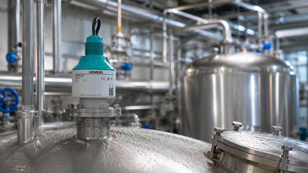
A radar level sensor operates reliably for months in a closed process vessel. The indicated level is stable and corresponds to the actual process conditions. However, after a change in process temperature, sporadic measurement jumps suddenly occur even though the actual level hardly changes.
When the vessel is opened, it becomes apparent that the radar antenna is covered with condensation. This can quickly lead to the assumption that radar is fundamentally unsuitable for the application. However, this conclusion would be too simplistic.
Modern radar level sensors can operate very reliably even under conditions of high humidity, process vapor, temperature changes and condensation. Problems mainly arise when moisture changes the reflection conditions directly around the antenna so significantly that additional false echoes occur or the actual product echo loses considerable signal margin relative to other reflections.
Different conditions must be distinguished. A thin, relatively uniform film of moisture can behave very differently from individual large droplets that grow, merge and eventually drip off. Temporary condensation must also not be confused with permanent product buildup, crystallization or contamination.
The mechanical installation also plays an important role. If the sensor is mounted deep inside a long nozzle, a relevant near-range echo may already be present under dry conditions. If condensation then forms on the antenna, the available signal margin can decrease to the point where the sensor temporarily tracks the wrong echo.
For troubleshooting, it is therefore not sufficient simply to determine that the antenna is wet. A more useful approach is to evaluate the antenna condition, installation, echo profile and process phase together. It is particularly valuable to determine whether the measurement jumps always occur during the same temperature or cleaning phase.
The decisive diagnostic question is therefore not: “Is the radar antenna wet?”, but rather: “Does the actual level echo remain clearly detectable under the occurring condensation conditions and maintain sufficient separation from false echoes in the near range?”
How Does Radar Level Measurement Work?
A radar level sensor transmits electromagnetic signals toward the surface of the medium. Part of the energy is reflected there and received again by the sensor. The level is then calculated from the measured distance between the sensor and the medium surface.
In simplified form, Level = distance to empty reference − measured distance. However, the sensor does not receive only the echo from the product surface. Mounting nozzles, vessel walls, pipes, heating coils, agitators and other internal structures can also reflect electromagnetic signals.
The actual task of the signal processing is therefore not merely to receive an echo. It must reliably determine which of the available echoes actually corresponds to the medium surface.
| Reflection Source | Typical Behavior | Importance for Measurement |
|---|---|---|
| Product surface | changes position with the level | desired measurement echo |
| Mounting nozzle | largely fixed in position | possible near-range false echo |
| Vessel internals | usually reproducible reflection | can compete with the product echo |
| Condensation droplets | change over time and in geometry | dynamic reflection near the antenna |
| Product buildup | often permanent or increasing | changes antenna and near-range echoes |
A particularly robust measuring point therefore has a strong product echo and as few competing reflections as possible. The clearer the echo conditions are under normal operation, the better the sensor can usually cope with changing process conditions.
Why Does Condensation Form on the Radar Antenna?
Condensation occurs when a humid process atmosphere comes into contact with a surface whose temperature is below the dew point of the gas or vapor mixture present. This situation occurs frequently in closed process vessels.
A hot medium can introduce large amounts of water vapor into the gas phase, while the vessel roof, mounting nozzle and radar antenna remain significantly cooler. Moisture then preferentially condenses on these colder surfaces.
The effect can be particularly pronounced during rapid temperature changes. Typical situations include filling a cold vessel with a hot product, cleaning with hot water or steam, or rapid cooling after a production step.
Thermal conditions can also change during extended shutdowns. A vessel that was uniformly warm during production may cool significantly in its upper section after shutdown while the medium and process atmosphere remain warm for some time.
Does Process Vapor Affect the Radar Signal?
Radar is generally well suited for many applications involving vapor and high humidity. The mere presence of water vapor therefore does not mean that reliable level measurement is impossible.
However, several effects must be considered separately for the specific measuring point. In addition to the gas phase itself, condensation on the antenna, changing droplet formation, foam on the medium surface, permanent product deposits and vessel internals can influence the actual echo quality.
In many applications, the greatest challenge is therefore not the uniformly present process vapor itself, but the changes it causes directly at the sensor. The situation can become particularly critical when large condensation droplets form on the antenna surface within a short period of time.
What Effect Do Condensation Droplets Have on the Antenna?
A uniform thin film of moisture does not necessarily behave in the same way as individual larger droplets. While a uniform film may have a relatively constant influence, individual droplets continuously change their size, shape and position.
They can grow, merge with one another and eventually run off or drip from the antenna. As a result, the reflection conditions in the immediate vicinity of the sensor change continuously.
| Antenna Condition | Typical Behavior | Possible Effect |
|---|---|---|
| Dry antenna | largely reproducible conditions | baseline for echo behavior |
| Thin moisture film | relatively uniform condition | may remain uncritical depending on the application |
| Individual large droplets | changing shape and position | dynamic near-range reflections possible |
| Strongly varying condensation | signal conditions change continuously | sporadic measurement jumps possible |
| Permanent product buildup | permanent additional reflecting surface | long-term deterioration of echo quality |
Droplet formation becomes particularly problematic if the actual product echo already has only a small margin relative to existing false echoes. In that case, even moderate changes around the antenna can cause a competing echo to become temporarily similar in strength or even stronger.
Distinguishing Condensation from Product Buildup
A wet antenna is not automatically a contaminated antenna. Temporary condensation usually depends strongly on temperature and the current process phase. It can form, change and disappear completely again after thermal stabilization.
Product buildup, on the other hand, is often permanent. Splashing, foam residues, sticky products, crystallization or dried process residues can remain on the antenna surface and continue to accumulate over time.
This distinction is crucial for troubleshooting. If the fault occurs only during a specific temperature transition and disappears again after cooling or drying, condensation is more likely. If the measuring point deteriorates continuously over a period of weeks, permanent buildup should also be considered.
False echo suppression can take changed reflection conditions into account. However, it does not remove physical product buildup from the antenna.
Understanding Echo Amplitude and Signal Margin Correctly
For reliable radar level measurement, the absolute strength of the product echo is not the only relevant factor. What matters most is how clearly this echo can be distinguished from noise and competing reflections.
In simplified terms, this separation can be considered the signal margin. If the product echo is clearly stronger and more distinct than the false echoes, the measuring point can remain robust even when conditions change.
If the margin is already small under dry conditions, additional reflections caused by condensation, foam or vessel internals may be enough to make the echo situation temporarily ambiguous.
A small signal margin can result, for example, from a long measuring distance, a poorly reflecting medium, unfavorable surface conditions, foam, strong vessel internals, an unsuitable mounting nozzle or existing product buildup on the antenna.
The fact that a sensor operates reliably for months with a dry antenna therefore does not automatically prove that the measuring point has sufficient margin to cope with strongly varying condensation.
How Condensation Can Change False Echoes
Fixed vessel internals such as pipes, braces or mounting nozzles create comparatively reproducible reflections. These signals can be identified during commissioning and taken into account during subsequent signal processing.
Condensation, however, is often dynamic. At the beginning of a temperature change, only a few small droplets may be present. A few minutes later, a much stronger moisture film may have formed, after which droplets run off and the antenna partially dries again.
The current reflection conditions can therefore differ considerably from the conditions under which false echo suppression was previously recorded.
This behavior explains why a measuring point can operate perfectly for a long time and only become unstable for a few minutes during certain process phases. Once thermal conditions stabilize, the echo pattern returns to normal and the sensor again tracks the correct product echo reliably.
Why the Near Range Is Particularly Critical
Condensation forms directly on or immediately in front of the radar antenna. Additional reflections therefore occur at a very short distance from the sensor and thus within the near range of the measurement.
This is precisely where other geometry-related reflection sources are often already present. Mounting nozzles, flange edges, protruding welded parts or the vessel roof can also create near-range echoes.
If several of these influences occur simultaneously, they can reinforce one another. An antenna covered with condensation droplets inside a long narrow nozzle is therefore significantly more critical than the same antenna with a clear view into the vessel.
In the event of sporadic measurement jumps, it should therefore be checked specifically whether the sensor is temporarily tracking a near-range echo instead of the actual product echo located farther away.
Considering Mounting Nozzles and Condensation Together
The mounting nozzle of a radar level sensor is more than just a mechanical connection. Its length, diameter and the position of the antenna influence both the electromagnetic and thermal conditions.
A long metal nozzle can generate its own reflections. At the same time, because of its connection to the vessel roof, this area can remain relatively cool and therefore promote condensation.
If the radar antenna is also positioned deep inside the nozzle, it is located precisely within this thermally unfavorable and electromagnetically reflective region.
A suitable installation therefore uses a nozzle that matches the sensor design, with an appropriate diameter and a length that is as uncritical as possible. The antenna position must comply with the manufacturer’s specifications.
In problematic applications, optimizing the nozzle design can be significantly more effective than simply changing software parameters.
Choosing the Correct Mounting Position
The radar beam should reach the relevant medium surface with as little interference as possible. The sensor should therefore not be aimed directly at a vessel wall, pipes, agitators, heating coils or other internals.
A filling stream is also an unfavorable direct measurement path. Falling product, splashing or strong surface movement can create additional echoes and may also promote contamination of the antenna.
Particularly in applications with recurring condensation, a clean basic installation geometry is valuable. The fewer fixed false echoes that are already present, the greater the remaining signal margin for changing process conditions.
Aligning the Sensor Correctly
For liquids with a largely horizontal surface, vertical alignment of the sensor is often the most favorable starting point. This directs the largest possible proportion of the radar energy toward the product surface.
Unintentional misalignment can cause more energy to strike the vessel wall, pipes or other internals. This may worsen the ratio between the desired product echo and false echoes.
However, a sensor should not be realigned solely because condensation is present without further diagnosis. The current echo or signal profile should first be examined. Only then can it be determined whether a different orientation would actually improve the measurement.
Considering Temperature Gradients Inside the Vessel
Condensation is often not a constant condition but becomes particularly strong during thermal transitions. This is why a measuring point can operate perfectly during normal production and only show problems after cleaning or during heating.
Assume that a tank and the installed radar sensor initially have a temperature of approximately 20 °C. A medium at 80 °C is then introduced. The humid gas phase heats up very quickly, while the massive vessel roof, mounting nozzle and sensor initially remain significantly colder.
During this phase, particularly large amounts of water vapor can condense on the cold surfaces. As operation continues, the vessel and sensor warm up and the amount of condensation decreases again.
A measuring point can therefore become unstable only during heating, cooling or other rapid temperature changes. This timing relationship is especially valuable for diagnosis.
Systematically Diagnosing Measurement Jumps
When sporadic level jumps occur, the configuration should not be changed immediately. The first step is to correlate the fault as precisely as possible with the actual process condition.
Relevant parameters include the actual level, indicated value, process temperature, vessel pressure, filling or emptying status and any cleaning cycles. It should also be documented whether agitators are operating and what condensation condition is present on the antenna.
| Observation | Possible Cause | Recommended Further Check |
|---|---|---|
| Fault only after hot cleaning | strong temporary condensation | check antenna condition and near-range echo during cleaning |
| Fault only when the tank is almost empty | weak product echo at long distance | compare signal margin and false echoes |
| Fault only when the tank is almost full | near range or minimum distance | investigate nozzle and upper-range echo behavior |
| Fault remains even with a dry antenna | product buildup, installation or configuration | inspect antenna, nozzle and echo profile |
| Measurement returns to normal after cooling | temperature-dependent condensation likely | compare temperature and fault trends |
| Echo quality deteriorates over several months | permanent buildup possible | inspect antenna for product deposits |
It is particularly informative to determine whether the fault always occurs during the same process phase. A clear correlation with hot cleaning or heating provides much stronger evidence of condensation influence than a measurement deviation that remains continuously present.
Using False Echo Suppression Correctly
Modern radar sensors can detect known unwanted reflections inside the vessel and take them into account during subsequent signal evaluation. This function is commonly referred to as false echo suppression.
It is particularly suitable for reproducible false echoes from mounting nozzles, ladders, pipes or other fixed vessel internals.
With condensation, however, caution is required. If false echo suppression is recorded during an extreme, temporary condensation condition, this situation may subsequently be treated as part of the normal vessel geometry. This can be unfavorable for later dry operating conditions.
Conversely, an older false echo suppression profile may no longer fit the measuring point optimally if the installation has changed permanently, for example because of new product buildup or mechanical modifications.
The mechanical and process-related condition of the measuring point should therefore be checked first. Permanent contamination should be removed and installation problems corrected. Only then should the signal profile be evaluated under representative conditions and false echo suppression adjusted or relearned if necessary.
False echo suppression should support a fundamentally well-designed measuring point. It should not be used to conceal an unfavorable installation or permanent contamination through software alone.
When Should the Antenna Be Cleaned?
Condensation alone does not necessarily require cleaning. When thermal conditions change, the antenna may dry by itself and the original echo quality may return completely.
Cleaning becomes much more relevant when permanent product buildup is present, crystals or solid residues form, or echo quality deteriorates progressively over extended operating periods.
A false reflection that remains clearly present under dry conditions and becomes stronger after longer production periods can also indicate permanent deposits.
During cleaning, process safety, material compatibility, manufacturer specifications and, where applicable, hazardous-area requirements must always be observed. The antenna surface must not be damaged mechanically with unsuitable tools.
Design Measures Against Condensation
Not every application involving condensation requires an immediate design change. If the measurement remains stable despite moisture, there is normally no reason to modify a functioning measuring point unnecessarily.
If disturbances occur repeatedly, however, it should be investigated whether the antenna and near-range area can be improved thermally or mechanically. A more favorable mounting position, a shorter or appropriately sized mounting nozzle, or the avoidance of particularly cold dead zones may improve the situation.
The appropriate sensor and antenna design must also be considered. Applications involving direct spray water or heavy buildup may require additional design measures.
An improvised cover placed directly in front of the radar antenna is generally not a suitable solution. Any additional component inside the radar beam can itself generate new reflections and merely shift the original problem elsewhere.
Practical Example: Measurement Jumps After Hot Vessel Cleaning
A stainless-steel vessel is continuously monitored using an 80 GHz radar sensor. During normal production, the level measurement operates reliably. Immediately after cleaning with hot water, however, the system indicates nearly 100% level for several minutes even though the vessel is actually almost empty.
The disturbance occurs reproducibly only after the hot cleaning cycle. Inspection of the sensor shows numerous condensation droplets on the antenna surface.
During this phase, the echo or signal profile shows a significantly stronger reflection in the near range. The actual echo from the almost empty product surface is located much farther away and at that moment has considerably less margin relative to the near-range signal.
Mechanical inspection also reveals that the sensor is mounted relatively deep inside a long metal nozzle. Even with a dry antenna, this nozzle already produces a relevant near-range echo.
The cause is therefore not condensation alone. The droplets reinforce an already unfavorable reflection situation in the near range.
The sensor is repositioned according to the installation instructions so that the antenna is not unnecessarily deep inside the nozzle. The echo behavior is then checked again and the false echo suppression is adjusted under representative conditions.
Condensation continues to form during subsequent cleaning cycles. However, the actual product echo remains clearly detectable and the level indication stays stable.
This example shows that the “wet antenna” alone was not the problem. Only the combination of condensation, the sensor’s near range and an already existing nozzle reflection resulted in the sporadic echo jumps.
Systematic Inspection of the Measuring Point
- Document exactly when the measurement deviation occurs.
- Record process temperature and relevant temperature changes at the same time.
- Inspect the antenna area for condensation and permanent product buildup.
- Distinguish between a thin moisture film, droplets and solid contamination.
- Check the mounting position of the radar sensor.
- Ensure that the radar beam is not directed at vessel internals or walls.
- Keep filling streams out of the direct measurement path wherever possible.
- Check the mounting nozzle for length, diameter and internal geometry.
- Verify that the antenna position complies with the manufacturer’s specifications.
- Evaluate the sensor’s echo or signal profile.
- Compare the product echo and relevant false echoes in terms of signal margin.
- Check whether the incorrect measurement is caused by a near-range reflection.
- Remove permanent contamination correctly if necessary.
- Evaluate false echo suppression only after the mechanical and process-related inspection.
- If the echo conditions have changed permanently, perform new false echo suppression under representative conditions.
- Compare measurements at low, medium and high levels.
- Investigate cleaning, heating and cooling phases specifically.
- Check whether the antenna design used is suitable for the application.
- Document echo quality as a long-term trend.
- After changes, observe the measuring point over several complete process cycles.
Common Mistakes
- Treating any condensation as a reason to rule out radar: Many radar level sensors operate reliably under humid and vapor-containing conditions.
- Looking only at the wet antenna: The combination of condensation, nozzle geometry, vessel internals and limited signal margin is often decisive.
- Equating product buildup with condensation: Permanent buildup behaves differently from temporary moisture.
- Immediately relearning false echo suppression: First determine why the reflection conditions have changed.
- Ignoring a long mounting nozzle: It can create both additional reflections and unfavorable thermal conditions.
- Mounting the sensor unnecessarily deep inside the nozzle: This can worsen the critical near range.
- Evaluating the measuring point at only one level: The relationship between product echo and false echoes changes with measuring distance.
- Confusing an echo jump with an actual level change: Incorrect echo selection can create an apparent large level change within seconds.
- Testing only during normal production: Disturbances may occur exclusively during cleaning, heating or cooling.
- Cleaning the antenna aggressively with mechanical tools: The antenna surface can be damaged.
- Installing improvised covers in front of the antenna: Additional components can create strong radar reflections themselves.
- Realigning the sensor without analyzing the echo profile: A different orientation can even increase existing false echoes.
- Considering only absolute echo amplitude: The separation between the product echo and competing reflections is equally important.
Suitable Radar Level Sensor
For compact industrial level measurements under demanding process and environmental conditions, the Siemens SITRANS LR100 series, for example, is suitable. The sensors use 80 GHz radar technology and enable non-contact continuous level measurement.
| Feature | Importance for the Application |
|---|---|
| 80 GHz radar technology | narrow measurement beam for compact vessel geometries |
| High signal sensitivity | supports echo detection even under demanding process conditions |
| Compact design | suitable for numerous industrial vessel applications |
| Bluetooth commissioning | wireless configuration and diagnostics |
| SITRANS Mobile IQ app | supports commissioning and device access |
| Various communication options | adaptation to different automation systems |
| Various approval options | selection according to the specific application |
For the application described here, the SITRANS LR110, for example, is of particular interest. It is suitable for industrial vessel applications and, depending on the version, provides corresponding communication and approval options.
The high signal sensitivity of modern 80 GHz radar systems supports reliable echo detection even under challenging conditions. Changing condensation or product buildup in the immediate antenna area should nevertheless be evaluated using the available diagnostic and echo information.
Further radar, hydrostatic, ultrasonic, capacitive and other continuous level measurement systems can be found under Level Measurement Technology at ICS Schneider.
Further information on mounting nozzles, vessel geometry and false echoes can be found in the article Configuring SITRANS LR Radar: Setting Up False Echo Suppression, Near Range and Vessel Geometry Correctly.
Conclusion
Condensation on a radar antenna does not automatically mean that the measuring principle is unsuitable for the application. Many radar level sensors can operate reliably under conditions of high humidity, vapor and changing temperatures.
The actual effect on the echo behavior is decisive. A thin, uniform moisture film can remain almost completely unnoticeable, while larger and changing condensation droplets directly on the antenna can create dynamic reflections.
The situation becomes particularly critical when additional false echoes are already present. Long mounting nozzles, flange edges, vessel internals, pipes or agitators can further reduce the available signal margin.
Installation is therefore an essential part of the solution. A favorably positioned antenna with a clear view of the product surface has considerably more margin for changing process conditions than a sensor mounted deep inside a reflective nozzle.
The timing relative to the process also provides important information. If the disturbance occurs exclusively immediately after hot cleaning or during a rapid heating phase and then disappears again, condensation is a likely influencing factor.
If echo quality remains permanently impaired even under dry conditions, product buildup, changed installation conditions or other permanent reflection sources must also be considered.
False echo suppression is a valuable tool, but it should only be used after the measuring point has been designed appropriately from both a mechanical and process perspective. It does not replace correct installation or the removal of permanent contamination.
The most important question is therefore not: “Are there droplets on the radar antenna?”, but rather: “Does the real level echo remain clearly detectable under all relevant process conditions and maintain sufficient signal margin relative to the changing false echoes?”
FAQ: Radar Level Measurement with Condensation
Can a radar level sensor measure reliably when condensation is present?
Yes. Radar is generally well suited for many applications involving humidity, vapor and condensation. The important factor is whether the actual level echo can still be identified clearly despite the changed conditions.
Can water droplets on a radar antenna interfere with measurement?
They can change the reflection conditions directly at the antenna. Whether this actually causes a measurement error depends, among other things, on droplet size, antenna design, measuring distance, product echo strength and the existing false echoes.
Why does the radar level suddenly jump to 100% when condensation occurs?
One possible cause is that a strong near-range reflection is temporarily interpreted as the relevant echo while the actual product echo is located farther away. Mounting nozzles and other near-range reflections can intensify this effect.
Is process vapor generally a problem for radar?
No. Radar can measure reliably in many applications containing process vapor. In practice, condensation on the antenna, foam, product buildup or vessel internals may have a greater influence on echo quality than the presence of vapor alone.
What is false echo suppression?
False echo suppression records known unwanted reflections inside the vessel and takes them into account during subsequent signal evaluation. Typical false echoes can originate from mounting nozzles, pipes, ladders or other fixed internals.
Should false echo suppression be relearned immediately when condensation occurs?
Not necessarily. The reason for the changed reflection conditions should be investigated first. Installation problems and permanent antenna contamination should be corrected before false echo suppression is reevaluated under representative conditions.
Why is the mounting nozzle so important?
A long or unsuitable mounting nozzle can generate relevant near-range reflections. At the same time, it can create a cooler region where condensation forms more readily. These two effects can reinforce one another.
Can a radar sensor be mounted deep inside a nozzle?
The permissible installation position depends on the specific sensor and nozzle geometry. Installation should comply with the manufacturer’s instructions and should avoid unnecessary reflections from the nozzle.
When should the radar antenna be cleaned?
Cleaning is particularly useful when permanent product buildup, crystallization or solid residues are present. Condensation alone can often disappear again by itself when the temperature conditions change.
How can I determine whether condensation is really the cause?
Time correlation is particularly helpful. If the incorrect measurement occurs only during hot cleaning, heating, cooling or other phases with strong condensation and disappears afterwards, a relationship is likely. The echo or signal profile should also be examined.
What does signal margin mean in radar measurement?
In simplified terms, it describes how clearly the actual product echo stands out from noise and competing false echoes. The greater this margin, the more robust the measurement remains when process conditions change.
Is 80 GHz radar better when condensation is present?
80 GHz radar sensors provide a narrow radar beam and can therefore often avoid vessel internals more effectively. High signal sensitivity is also useful. However, condensation directly on the antenna must still be considered during design and troubleshooting.
Can radar measure correctly even with a wet antenna?
Yes. The decisive factor is not simply whether the antenna is wet, but whether the actual level echo can still be tracked clearly. Light, uniform condensation may be uncritical, while large, changing droplets can create additional false echoes under unfavorable conditions.