


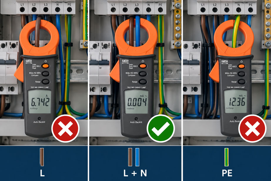
A leakage current clamp is placed around a conductor and shows 6.8 A. Is this a dangerously high leakage current?
Not necessarily.
If only the line conductor is enclosed, the clamp essentially measures the normal load current of the circuit.
If the same clamp is placed around the line conductor and neutral conductor simultaneously, it can measure the residual current remaining between the outgoing and returning currents.
If only the protective conductor is enclosed, the clamp instead measures the protective conductor current actually flowing through that conductor.
The position of the clamp therefore directly determines which electrical quantity is actually being measured.
This is particularly important when troubleshooting unwanted RCD trips.
In simplified terms:
Single active conductor → load current
All active conductors together → residual current
Protective conductor only → protective conductor current
For residual current measurement, all active conductors of the same circuit are enclosed by the clamp together. The protective conductor must not be included in the clamp.
How does a leakage current clamp work?
A current clamp detects the magnetic field generated by an electrical current in the enclosed conductor.
If only one conductor is enclosed, the magnetic field essentially corresponds to the current in that conductor.
If several conductors carrying currents in opposite directions are enclosed simultaneously, their magnetic fields are superimposed.
For a fault-free single-phase circuit, the following applies in simplified terms:
current out through L ≈ current back through N
The two currents flow in opposite directions.
Inside the current clamp, their magnetic effects therefore largely cancel each other out.
However, if part of the current returns via:
- the protective conductor,
- earth,
- equipotential bonding,
- machine housing,
- cable shield,
- pipework or another conductive connection
this current component is missing from the normal outgoing and return path.
The clamp detects the remaining difference.
This principle forms the basis of residual current measurement.
What is the difference between leakage current, residual current and protective conductor current?
In practical use, terms such as leakage current, fault current, protective conductor current and residual current are often used interchangeably.
For interpreting the measurement, it is helpful to distinguish between them.
Residual current:
The current difference between all active outgoing and return conductors of a circuit.
Protective conductor current:
The current actually flowing in the PE protective conductor.
Leakage current:
Current that flows to earth under normal operating conditions, for example via capacitive coupling, EMC filters or insulation.
Fault current:
Current that takes an unintended current path as a result of an insulation fault or incorrect connection.
Depending on where it is positioned, a leakage current clamp can make different components of these currents visible.
What does the clamp measure on a single conductor?
If the current clamp is placed around only one active conductor, it measures the total current in that conductor.
Example:
A load draws:
6.4 A
.
If only the line conductor L is enclosed, the clamp will indicate approximately:
6.4 A
.
This value is not leakage current.
It is primarily the normal operating or load current.
A high-resolution leakage current clamp can in principle also measure a single conductor, but the measurement then answers a completely different question.
A single active conductor is therefore the correct measuring point for load current measurement, not for conventional residual current measurement.
Why are all active conductors enclosed together for residual current measurement?
Residual current measurement is not intended to measure the load current itself.
Instead, only the proportion of current that does not return through the intended active conductors is of interest.
For this purpose, all active conductors of the relevant circuit are passed through the clamp together.
For a single-phase circuit:
L + N
For a three-phase circuit without neutral:
L1 + L2 + L3
For a three-phase circuit with neutral:
L1 + L2 + L3 + N
The protective conductor remains outside the clamp in each case.
Under normal conditions, the operating currents largely cancel each other within the clamp.
The displayed value then corresponds to the remaining residual current.
How is measurement performed on a single-phase circuit?
For a typical single-phase 230 V circuit:
L and N together
are enclosed by the clamp.
PE remains outside.
Example:
The current flowing through L is:
5.000 A
to the load.
The current returning through N is:
4.996 A
.
The difference is:
4 mA
.
A suitable leakage current clamp can detect this small residual current even though several amperes of operating current are flowing through the two conductors at the same time.
This is precisely the difference compared with a normal load current measurement.
How is measurement performed on a three-phase circuit?
For a three-phase load, all active conductors of the same circuit must likewise be inside the clamp.
Without a neutral conductor, this means:
L1 + L2 + L3
.
With a neutral conductor:
L1 + L2 + L3 + N
.
This principle also works with unbalanced loads.
A higher current on L1 than on L2 does not automatically mean there is a residual current, because the instantaneous or vector currents of the complete system are considered.
The decisive factor is whether the sum of all active conductor currents results in a residual current.
When must the neutral conductor also be included in the clamp?
If a neutral conductor is part of the circuit being tested, it must also be included in the residual current measurement.
For example, if only L is passed through the clamp in a single-phase circuit while N remains outside, the clamp will display the full load current.
The same applies to a three-phase four-wire system.
If only:
L1 + L2 + L3
are enclosed even though a relevant neutral current is flowing, the displayed value does not correspond to the desired residual current.
Basic rule: All current-carrying outgoing and return conductors of the same circuit must be measured together.
When is only the protective conductor measured?
A measurement on PE alone answers a different question:
How much current is actually flowing through this protective conductor?
Protective conductor current can be caused, for example, by:
- EMC filters,
- suppression capacitors,
- capacitive leakage currents,
- insulation faults,
- moisture,
- defective loads.
PE measurement is therefore very useful for troubleshooting.
However, it only shows the current flowing through this specific protective conductor.
It does not automatically include all other possible return paths to earth.
Why must PE not be included in a residual current measurement?
For conventional residual current measurement, the protective conductor must not be inside the clamp together with the active conductors.
Suppose a leakage current flows from L via a device housing to PE.
If the measurement includes:
L + N
this current appears as a difference because it does not return through N.
If PE is also included:
L + N + PE
the previously missing current also passes through the measuring opening again.
The magnetic effects can then cancel each other once more.
The displayed value may consequently become very small or almost zero even though a relevant leakage current is actually present.
All active conductors together: yes. Protective conductor additionally inside the clamp: no.
Why can residual current and protective conductor current differ?
In an idealised installation, one might expect:
residual current ≈ protective conductor current
In practice, however, this is not necessarily the case.
The reason is the presence of additional conductive connections.
A fault or leakage current may flow partly through:
- PE,
- cable shields,
- equipotential bonding,
- metal pipes,
- machine frames,
- building structures,
- other earthed components.
Residual current measurement around all active conductors generally detects the proportion of current that leaves the active circuit by another path.
PE measurement, on the other hand, only shows the current component in one particular protective conductor.
The two measurements therefore complement each other during troubleshooting.
What role do parallel earth and equipotential bonding paths play?
In complex industrial installations, there are often several galvanic connections between machines and earth.
These include, for example:
- protective conductors,
- equipotential bonding conductors,
- shielded motor cables,
- metal pipework,
- support structures,
- network cable shields.
A leakage current can therefore divide between several return paths.
For example, a measurement only on PE may indicate:
8 mA
while the residual current measurement on the associated outgoing circuit indicates:
14 mA
.
The difference does not automatically mean that one of the two measurements is incorrect.
Part of the current may return through another earth path.
Why must conductors from different circuits not be measured together arbitrarily?
For a meaningful residual current measurement, all conductors inside the clamp must belong to the same electrical circuit.
If, for example:
- L from circuit A and
- N from circuit B
are enclosed together, the currents have no defined relationship.
The clamp will then indicate a difference that may have nothing to do with the leakage current being investigated.
The same problem occurs when several outgoing circuits are only partially enclosed together.
Before the measurement, it must therefore be clearly established which conductors belong to which circuit.
What happens with shared neutral conductors?
Shared neutral conductors or neutral conductors connected together elsewhere can make troubleshooting significantly more difficult.
If the return current from one line conductor partly flows through another neutral path, a residual current will appear at the measuring point.
This does not necessarily have to be caused by an insulation fault to earth.
The following can also produce corresponding measurement patterns:
- incorrectly assigned neutral conductors,
- impermissible neutral connections,
- wiring faults,
- several interconnected circuits.
An abnormal residual current measurement is therefore initially a diagnostic indication and not yet a complete identification of the fault cause.
What must be considered with parallel conductors?
At high power levels, line conductors may consist of several individual conductors connected in parallel.
For complete residual current measurement, all parallel conductors of the respective active current path must then be taken into account.
If, for example, only one of two parallel L1 conductors passes through the clamp while both neutral conductors and the remaining phases are fully included, the measuring setup alone will create a large apparent residual current.
For large conductor bundles, a sufficiently large clamp opening is therefore also required.
How does a leakage current clamp help with unwanted RCD trips?
A common application for a leakage current clamp is troubleshooting an RCD that trips intermittently or unexpectedly.
A useful strategy is to begin by measuring the entire affected outgoing circuit.
For this purpose, all active conductors are measured together.
If the residual current is abnormal, the system can then be subdivided further:
main outgoing circuit → sub-distribution → individual circuit → individual load
In this way, the circuit making the largest contribution can be located step by step.
Leakage current measurement does not replace the RCD test required by applicable standards.
It is primarily a powerful diagnostic tool for troubleshooting.
Why are frequency converters and mains filters particularly relevant?
Electronic loads can generate relevant leakage currents even without a conventional insulation fault.
Typical examples include:
- frequency converters,
- switch-mode power supplies,
- servo drives,
- UPS systems,
- mains filters,
- long shielded motor cables.
EMC filters often contain capacitors connected to earth.
In addition, rapidly switching power semiconductors generate high-frequency common-mode currents.
The measured leakage currents can therefore be:
- frequency-dependent,
- load-dependent,
- dependent on the operating condition
.
A high residual current therefore does not automatically mean that the cable insulation is damaged.
The respective load and its normal leakage current behaviour must be taken into account.
What role do frequency range and filters play?
A leakage current clamp does not necessarily detect every current component equally regardless of frequency.
With electronic loads, higher-frequency currents can occur in addition to 50 Hz or 60 Hz components.
A switchable filter can be useful when specifically distinguishing between:
- the mains-frequency component and
- higher-frequency interference or leakage currents
.
However, the filter function must not be used indiscriminately.
Depending on the diagnostic question, the high-frequency component may be particularly relevant.
Before evaluating the measurement, it should therefore be known which frequency range is actually detected by the measuring instrument or selected filter.
Can every leakage current clamp also measure DC residual currents?
No.
Many conventional residual-current or leakage-current clamps measure alternating current only.
Such a device may, for example, measure very small AC leakage currents precisely but will not measure a smooth DC residual current.
This must be taken into account particularly in installations with:
- power electronics,
- PV inverters,
- frequency converters,
- charging equipment,
- DC link circuits.
When selecting the instrument, it must therefore first be established which type of current actually needs to be measured.
An AC leakage current clamp must not automatically be interpreted as a measuring instrument for both AC and DC residual currents.
How should the clamp be positioned mechanically?
For small residual currents, correct mechanical application is also important.
Before measuring, check that:
- the clamp jaws close completely,
- there is no contamination on the mating surfaces,
- the conductors are completely inside the measuring opening,
- the clamp is not mechanically strained,
- the conductors are positioned as favourably as possible within the opening.
A clamp that is only partially closed can significantly impair measurement accuracy.
Especially for measurements in the µA or low mA range, more care is therefore required than for a rough load current measurement.
How do high load currents and magnetic fields influence the measurement?
Residual current measurement determines a very small remaining current in the presence of much larger operating currents.
For example:
20 A load current
may flow through the outgoing and return conductors while the value being investigated is:
5 mA residual current
.
The ratio between the two quantities is very large.
Therefore:
- unfavourable conductor position,
- clamp jaws not fully closed,
- strong adjacent magnetic fields,
- large busbars immediately next to the clamp
can influence the measurement more strongly than during a normal current measurement.
Repeat measurements with the clamp positioned as reproducibly as possible help verify abnormal readings.
Which measuring range is appropriate?
Leakage and fault currents are often considerably lower than normal load current.
A conventional current clamp with, for example:
0 ... 600 A
measuring range and low resolution is therefore not automatically suitable.
For diagnosing small residual currents, the following are particularly important:
- a low lower measuring range,
- high resolution,
- sufficient accuracy,
- TRMS measurement for non-sinusoidal currents,
- a suitable frequency range.
The largest available measuring range is not automatically the best choice for leakage current measurement.
The decisive factor is that the expected fault current can be displayed with sufficient resolution.
What must be considered when working on electrical installations?
A current clamp generally allows current to be measured without electrically disconnecting the conductor.
However, this does not mean that every measurement in an open distribution board is automatically safe.
Before measuring, particular consideration must be given to:
- the qualification of the person carrying out the work,
- the permitted operating condition of the installation,
- protection against electric shock,
- the measurement category of the instrument,
- the maximum permissible voltage,
- company safety rules and working procedures.
Conductors should not be rearranged or separated while live solely for the purpose of making a measurement if this creates a hazard.
If no suitable measuring point exists, a safe test setup must first be established.
The protective conductor must not be interrupted for a leakage current measurement.
Practical example: RCD trips intermittently
An RCD in a workshop trips irregularly.
Several machines are connected to the affected sub-distribution board.
First, the leakage current clamp is placed around:
L1 + L2 + L3 + N
of the affected outgoing circuit.
PE remains outside.
The indicated value is:
18 mA
.
The individual downstream circuits are then measured in the same way.
Several smaller loads together cause:
6 mA
.
A circuit with a frequency converter contributes another:
11 mA
.
When the motor accelerates, this value increases significantly for a short period.
The measurement on the associated PE also shows a current, but not exactly the same value as the residual current measurement.
The machine also has a shielded motor cable and metallic equipotential bonding connections.
This makes the following clear:
The RCD trip is not caused by one single major insulation fault, but by the sum of several operational leakage currents plus an additional dynamic component from the drive system.
Only the correct measurement around all active conductors made it possible to compare systematically the actual contribution from the individual circuits.
Systematically narrowing down residual current faults
- Clearly identify the affected circuit.
- Determine the supply system and conductor assignment.
- Check whether a neutral conductor is present.
- Select a suitable leakage current clamp.
- Check the measurement category and permissible voltage.
- Enclose all active conductors of the outgoing circuit together.
- Keep PE outside the clamp.
- Measure residual current under normal operating conditions.
- Repeat the measurement under changing load conditions.
- Compare downstream circuits step by step.
- If required, measure the protective conductor separately.
- Take parallel earth and shield paths into account.
- Identify electronic loads and frequency converters.
- Check the frequency range or filter setting.
- Then investigate the abnormal load further using appropriate test methods.
Which measuring setup answers which question?
| Clamp position | What is measured? | Typical application |
|---|---|---|
| L only or one individual phase | Load current of this conductor | Checking operating current |
| L + N | Residual current of the single-phase circuit | Searching for leakage/fault current |
| L1 + L2 + L3 | Residual current of a three-phase circuit without N | Fault current on a three-phase load |
| L1 + L2 + L3 + N | Residual current of a three-phase circuit with N | Fault current in a four-wire system |
| PE only | Protective conductor current | Investigating current in the specific protective conductor |
| Active conductors + PE | Can largely cancel out | Unsuitable for conventional residual current measurement |
Common measuring errors
- Enclosing only one phase and interpreting the reading as leakage current: The measurement is primarily the load current.
- Forgetting the neutral conductor during residual current measurement: In a circuit with N, the neutral must also pass through the clamp.
- Enclosing the protective conductor together with L and N: The residual current being sought can cancel out again inside the clamp.
- Measuring only PE and treating the value as the total residual current: Other earth and equipotential bonding paths are not included.
- Mixing conductors from different circuits: The resulting difference has no clear meaning.
- Overlooking shared neutral conductors: Return currents may flow outside the expected measuring path.
- Only partially enclosing parallel conductors: This creates an apparently very large residual current.
- Enclosing all conductors of a cable including PE: The fault current can cancel magnetically.
- Using a standard current clamp with insufficient resolution: Small fault currents disappear within the instrument resolution.
- Using an AC instrument for DC fault current: Not every leakage current clamp detects DC components.
- Not fully closing the clamp jaws: Small currents in particular may then be measured incorrectly.
- Ignoring large nearby conductors: Strong external magnetic fields can influence sensitive measurements.
- Switching on a filter without considering the diagnostic question: Relevant high-frequency components may be suppressed.
- Treating one instantaneous reading as a complete diagnosis: Many fault and leakage currents depend on load and operating condition.
- Equating RCD troubleshooting with RCD testing: Leakage current measurement does not replace the prescribed protective-measure testing.
HT77N and HT78 for residual current measurements
HT77N
The HT77N is an AC current clamp for measuring small fault and leakage currents.
The AC TRMS measuring range extends from:
10 µA to 100 A
.
In the smallest range, a resolution of up to:
1 µA
is available.
This makes the clamp particularly suitable for troubleshooting circuits in which RCDs repeatedly trip unintentionally.
The maximum opening for cables or conductor bundles is:
40 mm
.
The overvoltage category is:
CAT III 300 V
.
The HT77N is therefore particularly suitable for:
- small AC residual currents,
- protective conductor current measurements,
- troubleshooting RCD circuits,
- measurements in the µA and mA range.
Further information can be found for the HT77N AC current clamp for measuring fault currents.
HT78 for large conductor bundles
For larger cables or several conductors that need to be enclosed together, a larger clamp opening may be required.
The HT78 has a maximum opening of up to:
108 mm
.
The AC TRMS measuring range extends from:
0.1 mA to 3000 A
.
A switchable low-pass filter is also available.
This makes the HT78 particularly useful for larger cable bundles or industrial applications.
Further residual-current clamps can be found under leakage current clamps / residual current at ICS Schneider.
The complete overview can be found under electrical measuring and test instruments at ICS Schneider.
Conclusion
When measuring leakage current, the position of the clamp determines which electrical quantity is actually being measured.
A clamp around a single line conductor primarily measures the load current.
For conventional residual current measurement, however, all active conductors of the same circuit must be enclosed together.
For a single-phase circuit, these are:
L + N
.
For a three-phase circuit with neutral:
L1 + L2 + L3 + N
.
The protective conductor remains outside the clamp.
A separate measurement on PE alone, by contrast, provides the current actually returning through that protective conductor.
Residual current and PE current do not have to be identical because real installations can contain additional return paths via equipotential bonding, cable shields, pipework or machine structures.
For a meaningful diagnosis, neutral conductor assignment, parallel conductors, frequency range, possible DC components and the operating condition of the loads must also be taken into account.
The most important rule is therefore: If the residual current of a circuit is to be measured, all active conductors of that circuit must pass through the leakage current clamp together – but the protective conductor must not. If the current in PE is to be investigated specifically, only the protective conductor is enclosed.
FAQ: Positioning a leakage current clamp correctly
Does a leakage current clamp have to be placed around a single conductor?
Only if the current in that individual conductor is to be measured. For residual current measurement, all active conductors of the circuit are enclosed together.
Which conductors must pass through the clamp in a single-phase circuit?
For residual current measurement, line conductor L and neutral conductor N are enclosed together. Protective conductor PE remains outside.
Which conductors must pass through the clamp in a three-phase circuit?
Without a neutral conductor, L1, L2 and L3 are enclosed together. If a neutral conductor is present and is part of the circuit, L1, L2, L3 and N must all be enclosed together.
May the protective conductor be included in the clamp during residual current measurement?
No. If the fault current returns via PE and PE is also enclosed, this current can cancel again inside the clamp together with the active conductor currents.
What do I measure if I enclose only the protective conductor?
Then the current actually flowing through that protective conductor is measured. This is commonly referred to as protective conductor current.
Is protective conductor current always equal to residual current?
No. Part of the leakage or fault current can return via cable shields, equipotential bonding, pipework, machine frames or other earthed connections.
Why does the clamp show several amperes on a single line conductor?
Because it is measuring the normal operating or load current there. This value must not be confused with leakage current.
Can I simply enclose an entire five-core cable with the clamp?
Not for conventional residual current measurement if PE is also contained in the cable and enclosed by the clamp. A measuring point is required where the active conductors can be measured together while PE is kept separate.
Why does the leakage current clamp show several milliamperes even though the insulation is intact?
Electronic loads and EMC filters can inherently generate capacitive leakage currents to earth. A measured residual current therefore does not automatically indicate an insulation fault.
Can a frequency converter cause high leakage currents?
Yes. EMC filters, fast switching operations and shielded motor cables can generate frequency-dependent leakage or common-mode currents.
Does the HT77N also measure DC residual currents?
The HT77N is designed for AC TRMS current measurements. For applications where DC or smooth DC residual-current components are relevant, a suitable measuring method or instrument must be selected.
Why is high resolution important?
During troubleshooting, residual currents in the µA or mA range are often measured while operating currents of several amperes are flowing at the same time. A conventional load-current clamp often does not provide the required resolution for this.
Can a leakage current clamp test an RCD?
It is highly suitable for diagnosing leakage and residual currents. However, standards-compliant functional and trip testing of an RCD requires an appropriate test instrument or test procedure.
Which leakage current clamp is suitable for small fault currents?
One example is the HT77N. It measures AC TRMS currents from 10 µA and provides a resolution of 1 µA in its smallest range.
What can I do if all active conductors do not fit inside the clamp?
A current clamp with a larger opening or another suitable measuring point is then required. For large conductor bundles, for example, the HT78 with an opening of up to 108 mm may be suitable.