


A current transformer has been selected to match the primary current, the transformation ratio is correct, and the connected measuring device also has the appropriate 1 A or 5 A input. Nevertheless, the measurement shows larger deviations than expected. This problem is particularly noticeable when the current transformer and measuring device are not installed directly next to each other, but are separated by several metres or even several tens of metres of secondary cable.
In such cases, attention is often focused only on the transformation ratio of the current transformer. However, an equally important parameter is the burden of the secondary circuit. The current transformer must not only drive the current input of the measuring device, but also overcome the resistance of the complete outgoing and return cable as well as any other components present in the secondary circuit.
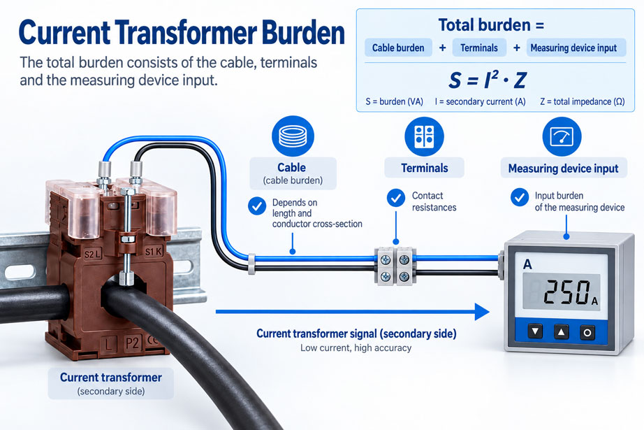
For reliable current measurement, the entire secondary burden must therefore be considered. Measuring device input, cable length, conductor cross-section, terminals and other components connected in series must all be compatible with the permissible burden of the current transformer.
What does the burden of a current transformer mean?
A conventional measuring current transformer converts a high primary current into a significantly lower secondary current. Typical rated secondary currents are 5 A and 1 A. With a 400/5 A current transformer, for example, a primary current of 400 A corresponds to a secondary current of 5 A under rated conditions.
This secondary current flows through a closed circuit. This typically includes the secondary winding of the current transformer, the connecting cable, terminals and the current input of the connected measuring device. Every external resistance or impedance through which the secondary current has to flow places a load on the current transformer.
This external load is referred to as the burden. For current transformers, it is commonly specified as apparent power in volt-amperes, abbreviated VA.
The nameplate or data sheet of a current transformer may, for example, state values such as 2.5 VA, 5 VA, 10 VA or 15 VA together with an accuracy class. These values must not be confused with the power of the primary load. They refer to the secondary circuit of the instrument transformer.
What does the VA rating mean?
For a predominantly resistive secondary circuit, the relationship between secondary current, impedance and burden can be approximately described by the following formula:
S = I² × Z
Where:
- S = burden in VA
- I = secondary current in A
- Z = impedance of the connected secondary circuit in Ω
For a copper cable, the inductive component is often sufficiently small over typical cable lengths that the ohmic resistance can initially be used for an approximate cable calculation:
S ≈ I² × R
This formula already reveals one decisive point: The secondary current has a quadratic influence on the cable burden.
With the same cable impedance, a 5 A secondary circuit therefore produces not just five times, but 25 times the burden of a 1 A secondary circuit.
5² / 1² = 25
This is precisely why the choice between 1 A and 5 A becomes particularly important when longer distances between the current transformer and measuring device have to be bridged.
What is included in the total burden?
When sizing the current transformer, it is not sufficient to consider only the measuring device input. The entire external load on the current transformer is decisive.
In simplified form:
Stotal = Smeasuring device + Scable + Sother components
The total burden may include, among other things:
- current input of the measuring device or energy meter,
- outgoing and return cable between the current transformer and measuring device,
- test and disconnect terminals,
- additional measuring devices in the secondary circuit,
- transmitters or protection devices, provided they are connected in this circuit,
- contact resistances at connections and terminals.
In a properly assembled control cabinet, the contact resistances of good terminal connections are normally significantly lower than the resistance of a long secondary cable. However, aged, loose or corroded connections can make an additional relevant contribution.
Correctly calculating cable burden
Over longer distances, the secondary cable is often the most significant additional component of the burden. The complete current loop must always be taken into account: the secondary current flows from the current transformer to the measuring device and then back again.
For a simple two-wire connection, the following approximation applies:
Rcable = ρ × (2 × l) / A
Where:
- ρ = resistivity of the conductor material,
- l = one-way distance between the current transformer and measuring device,
- A = conductor cross-section.
For copper at room temperature, an approximate value of 0.0178 Ω × mm²/m can be used.
Example: 10 m distance with 2.5 mm²
The current transformer is located 10 m from the measuring device. The total electrical conductor length is therefore:
2 × 10 m = 20 m
With a conductor cross-section of 2.5 mm², the approximate resistance is:
R = 0.0178 × 20 / 2.5
R ≈ 0.142 Ω
At first glance, 0.142 Ω appears small. However, with a 5 A current transformer it already results in:
S = 5² × 0.142
S ≈ 3.55 VA
In this example, the connecting cable alone therefore already accounts for approximately 3.6 VA. The measuring device input has not yet been included.
Why 1 A offers advantages with long cable runs
Now consider the same cable with a 1 A current transformer. The cable resistance remains unchanged at approximately 0.142 Ω.
The burden is now:
S = 1² × 0.142
S ≈ 0.142 VA
For the same cable, this gives:
- 5 A: approximately 3.55 VA
- 1 A: approximately 0.142 VA
The cable burden of the 5 A circuit is therefore 25 times higher.
This does not mean that 1 A current transformers are inherently better. With short cable runs and existing 5 A measuring devices, a 5 A version may be entirely appropriate. However, over longer distances between the current transformer and evaluation device, the lower cable burden of a 1 A system quickly becomes a significant advantage.
Of course, the connected measuring device must be designed for a secondary current of 1 A or must be configurable accordingly.
Consider the measuring device input
The input of the connected measuring device also has a burden. This is often specified directly in VA in the technical data sheet. Some manufacturers instead specify the input impedance or input resistance.
If the resistance is specified, the burden can also be calculated:
Smeasuring device = I² × Zinput
Modern digital measuring devices often have a relatively low input burden. Nevertheless, it should not automatically be ignored.
This becomes particularly important when several devices are to be supplied from the same current transformer. If suitable current inputs are connected in series in the same secondary circuit, their burdens are added together.
Example:
- Measuring device 1: 0.5 VA
- Measuring device 2: 0.5 VA
- Secondary cable: 3.5 VA
The total external burden is therefore already:
0.5 VA + 0.5 VA + 3.5 VA = 4.5 VA
With a current transformer rated for only 5 VA burden, the remaining margin would already be very small.
Practical example: 5 A current transformer
A control cabinet builder wants to measure an operating current using a 400/5 A current transformer. The current transformer used has a rated burden of 5 VA. The measuring device is located 12 m from the current transformer.
Given:
- Current transformer: 400/5 A
- Rated burden: 5 VA
- one-way cable length: 12 m
- conductor cross-section: 2.5 mm² Cu
- measuring device burden: 0.5 VA
The total conductor length is:
2 × 12 m = 24 m
The approximate cable resistance is:
R = 0.0178 × 24 / 2.5
R ≈ 0.171 Ω
At 5 A, this results in:
Scable = 25 × 0.171
Scable ≈ 4.28 VA
Together with the measuring device:
Stotal = 4.28 VA + 0.5 VA
Stotal ≈ 4.78 VA
The calculated total burden is therefore already very close to the 5 VA rating of the current transformer. Additional terminals, further devices or an unfavourable installation leave practically no reserve.
The solution should not be to ignore the cable length in the calculation. Suitable measures could include using a larger conductor cross-section, selecting a current transformer with an appropriate higher rated burden or – if permitted by the measuring device and system concept – using a 1 A secondary circuit.
The same example with 1 A
If the same installation is designed using a suitable 400/1 A current transformer and a measuring device input intended for 1 A, the cable resistance remains unchanged:
R ≈ 0.171 Ω
At 1 A, however, the cable burden is only:
Scable = 1² × 0.171
Scable ≈ 0.171 VA
The difference between approximately 4.28 VA and only 0.171 VA shows why 1 A secondary circuits can be attractive for longer cable runs.
However, the complete measuring chain remains decisive. An existing measuring device with an exclusively 5 A current input cannot simply be connected to a 1 A transformer unless the input, scaling and device specification are suitable for it.
What happens if the burden is too high?
A current transformer can only provide the required secondary current within its design limits and with the specified accuracy. As the external burden increases, the transformer must generate a higher secondary voltage in order to drive the corresponding current through the measuring circuit.
If the load specified for the respective version is exceeded, the measurement error may increase. Depending on the current transformer, operating current and burden, the magnetic core may be subjected to greater stress and may enter operating regions earlier in which the transfer characteristics no longer correspond to the specified accuracy class.
A higher VA rating on the nameplate is therefore not simply an arbitrary reserve value. Current transformer, accuracy class, secondary current and actual burden must be considered as interrelated parameters.
Conversely, an extremely low burden should not automatically be assumed to guarantee an improvement in accuracy class. The specified error limits apply under the technical conditions defined in the data sheet or applicable to the current transformer. For precise measurement tasks, the specific manufacturer’s data sheet should therefore always be consulted.
Systematically sizing a current transformer
A simple procedure has proven useful for practical planning.
1. Determine the primary current
First, the actual operating current of the installation must be known. The selected rated primary current of the current transformer should be appropriately matched to the intended measuring range.
2. Define the secondary current
Next, decide whether a 1 A or 5 A secondary circuit is to be used. Existing measuring devices and energy meters must be taken into account.
3. Determine the measuring device burden
The burden of the current input is taken from the measuring device data sheet. If several suitable current inputs are connected in series, their burdens must be added together.
4. Determine the cable length
The complete current loop must be taken into account when calculating resistance. With a distance of 15 m between the current transformer and measuring device, a two-wire connection therefore results in approximately 30 m of total conductor length.
5. Consider the conductor cross-section
A larger cross-section reduces cable resistance and therefore cable burden. Particularly in 5 A systems, this can make a significant difference.
6. Include additional components
Test terminals, measuring devices, transmitters or other components in the secondary circuit must be included in the assessment.
7. Calculate the total burden
All external burdens are added together and compared with the data of the intended current transformer.
8. Check the accuracy requirement
Finally, it must be verified whether the selected transformer provides the required accuracy class and meets the other requirements of the measuring task at the intended burden.
Practical example from control cabinet construction
In a main distribution board, three current transformers are installed directly on the busbars. However, the central power monitoring device is located several metres away in a separate metering panel.
Originally, 5 A current transformers were planned. During detailed engineering, it becomes apparent that each phase requires a longer cable run to the measuring device. If cable length and conductor cross-section are not taken into account, the actual burden can be significantly higher than if the measuring device were installed immediately next to the current transformers.
A sensible design therefore compares different options:
- larger cross-section of the secondary cables,
- shorter cable run,
- current transformer with a suitable VA rating,
- 1 A system instead of 5 A, provided the measuring device supports it.
Particularly in new installations, this check should be carried out before the current transformer and measuring device are ordered. Changing the secondary current later may require replacement of the current transformers or evaluation devices.
Systematic testing and diagnostic procedure
If there is reason to suspect that an existing current transformer circuit is problematic because of its burden, the installation can be checked systematically.
- Check the current transformer nameplate: Note primary current, secondary current, accuracy class and VA rating.
- Check the measuring device: Is the input actually designed for 1 A or 5 A and is it configured correctly?
- Determine the measuring device burden from the data sheet.
- Determine the cable length: Include outgoing and return conductors.
- Check the conductor cross-section.
- Calculate or professionally measure the cable resistance.
- Calculate the cable burden using I² × R.
- Identify additional devices and components in the secondary circuit.
- Calculate the total burden and compare it with the current transformer data.
- Check terminals and connections for loose or damaged connections.
- Then verify the plausibility of the measured values against a suitable reference.
This procedure usually makes it possible to determine quickly whether the burden is actually the problem or whether, for example, an incorrect transformation ratio, incorrect parameterisation or a wiring error is responsible.
Never open the secondary circuit uncontrolled
For conventional 1 A and 5 A current transformers, one important safety rule applies: The secondary circuit must never be opened uncontrolled while primary current is flowing.
A current transformer continues attempting to generate a secondary current corresponding to the primary current. If the secondary circuit is interrupted, a high voltage may therefore develop across the open secondary winding. This can endanger personnel, stress the insulation and damage the current transformer.
Measuring devices must therefore not simply be disconnected from an energised current transformer circuit. Suitable short-circuiting, test or disconnect terminals are used for maintenance and testing so that the secondary winding can be safely short-circuited in accordance with the intended system and safety concept before the measuring circuit is opened.
Common sizing errors
Considering only the VA rating of the measuring device
With longer secondary cables, the cable burden can be significantly greater than the burden of the actual measuring device.
Using only the one-way cable length
The current must flow to the measuring device and back again. For the resistance calculation of a two-wire connection, the complete current loop must therefore be taken into account.
Treating 5 A and 1 A in the same way
The cable burden increases with the square of the secondary current. Changing from 1 A to 5 A therefore increases it by a factor of 25 at the same cable impedance.
Ignoring conductor cross-section
A thinner conductor has a higher resistance and produces a greater burden at the same secondary current.
Forgetting additional measuring devices
If several suitable current inputs are connected in series in the same secondary circuit, their burdens must be considered together.
Selecting only by primary current and transformation ratio
The specification 400/5 A alone is not sufficient for selecting a current transformer. Accuracy class, burden, design, conductor or busbar dimensions and operating conditions must also be taken into account.
Opening the secondary circuit during operation
This is not a normal measuring condition and can generate dangerous voltages. Maintenance work must be carried out using the designated short-circuiting and test equipment.
Suitable current transformers from ICS Schneider
ICS Schneider Messtechnik offers various current transformers for measuring, energy monitoring and supervision tasks in low-voltage installations.
Depending on the application, the available designs include window-type current transformers, precision current transformers, wound-primary current transformers, split-core current transformers, summation current transformers and other versions.
When selecting a current transformer, not only the primary current and mechanical dimensions should be considered. The following are equally important:
- rated secondary current of 1 A or 5 A,
- required accuracy class,
- rated burden in VA,
- cable length to the measuring device,
- burden of the measuring device input,
- conductor or busbar dimensions,
- measurement or protection application.
Overview of current and voltage transformers at ICS Schneider
Window-type current transformers for measurement applications
View precision current transformers
Conclusion
The correct burden of a current transformer cannot be determined solely from the connected measuring device. The complete secondary circuit must be considered.
Measuring device burden + cable burden + other external loads = total current transformer burden.
The influence of the secondary current is particularly important. Because the cable burden increases proportionally to I², a 5 A current transformer produces 25 times the cable burden of a 1 A current transformer at the same cable impedance.
With short cable runs, this is often uncritical. Over longer distances, however, the cable can consume a significant proportion of the available VA rating. Cable length and conductor cross-section should therefore be sized together with the current transformer and measuring device during the planning stage.
By considering primary current, secondary current, rated burden, cable resistance and measuring device input together, a measuring chain can be created that not only works correctly in theory but also operates reliably under real installation conditions.
FAQ on current transformer burden
What is the burden of a current transformer?
The burden is the electrical load presented to the current transformer by the connected secondary circuit. It includes, in particular, the measuring device input, connecting cables and other components connected in series. For current transformers, it is commonly specified in VA.
What does 5 VA mean for a current transformer?
The rating describes a rated burden of the secondary circuit to which the specified characteristics of the current transformer refer. The specific accuracy conditions are stated in the relevant data sheet.
How is the burden of a current transformer calculated?
For a predominantly resistive load, the approximation S = I² × R can be used. The total burden is the sum of the burdens of the measuring device, cable and other components in the secondary circuit.
Do the outgoing and return cable lengths both need to be considered?
Yes. In a two-wire connection, the secondary current flows to the measuring device through one conductor and returns through the second conductor. With a physical distance of 10 m, approximately 20 m of total conductor length must therefore be included in the resistance calculation.
Why is the cable more critical with a 5 A current transformer?
The power loss or burden of a resistive cable increases with the square of the current. At the same cable impedance, a 5 A secondary circuit therefore produces 25 times the cable burden of a 1 A secondary circuit.
When is a 1 A current transformer useful?
1 A current transformers can be particularly useful over longer distances between the current transformer and measuring device because the secondary cable accounts for significantly less VA. However, the connected measuring device must be suitable for 1 A.
Can I connect a 1 A current transformer to a 5 A measuring device input?
The current transformer and measuring device must be compatible in terms of secondary current and parameterisation. A 1 A transformer must not simply be used as a replacement for a 5 A transformer if the input or evaluation system is not designed for it.
Can a larger conductor cross-section reduce the burden?
Yes. A larger copper conductor cross-section reduces cable resistance and therefore cable burden. This can be particularly effective with 5 A secondary circuits and long cable runs.
What happens if the burden is too high?
As the burden increases, the current transformer must generate a higher secondary voltage. If the load specified for the respective design is exceeded, ratio and phase errors may increase, and at high currents the current transformer may enter an unfavourable magnetic operating region earlier.
Can the secondary circuit of a current transformer be opened?
Not uncontrolled while a relevant primary current is flowing. High voltages can occur with an open secondary circuit. Suitable short-circuiting, test or disconnect terminals and the designated safety procedure must be used for maintenance work.
Do terminals need to be considered when calculating the burden?
In principle, every series impedance forms part of the secondary circuit. With correctly installed connections, the influence of individual terminals is often small. However, poor, loose or corroded contacts can increase the resistance and should be checked, particularly in existing installations.
Is a current transformer with the highest possible VA rating automatically better?
No. The current transformer should be selected to suit the actual measuring chain, required accuracy and application. The VA rating is only one of several relevant parameters.
What information is required to select a current transformer?
Typically, the rated primary current, desired secondary current, accuracy class, required burden, cable length, conductor cross-section, measuring device burden, design and mechanical dimensions of the primary conductor or busbar are required.