


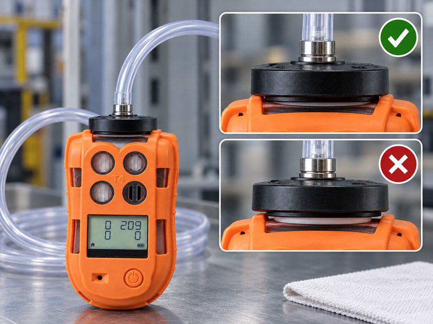
A portable gas detector is exposed to test gas before use. The cylinder contains the correct gas concentration and is still within its specified period of use. Nevertheless, one sensor responds unusually slowly or does not reach the expected reading. Does this already prove that the sensor is defective or incorrectly calibrated?
No. Between the test gas cylinder and the sensor there is a complete pneumatic test path:
Test gas cylinder → regulator → hose → test adapter → sensor
If the gas flow is too low at any point, the adapter is leaking, a hose is kinked or the gas supply is not correctly matched to the respective instrument, the sensor may be exposed to different test gas conditions than intended.
This is particularly critical because a bump test is intended to be a functional test under defined conditions. The gas must reach the sensors within the specified time and cause a sufficient response, including activation of the intended alarm functions.
An abnormal bump-test result should therefore not immediately be interpreted as a sensor fault. First, the test gas, regulator, flow rate, hose, adapter seal, gas transport time and the test duration specified by the manufacturer must be checked systematically.
What does a bump test check?
A bump test is a functional test of a gas detector using a suitable test gas.
In simplified terms, it checks whether:
- the test gas reaches the sensors,
- the sensors respond to the gas,
- the response occurs within the specified time,
- the required alarms are activated.
For this purpose, a gas with a known composition is supplied to the instrument.
The test is therefore intended to answer an important practical question:
Does the gas detector respond to actual gas exposure?
A bump test therefore checks considerably more than just the electronics of the display.
It also includes the actual sensor and its gas access path.
Why is a bump test not a calibration?
A bump test and a calibration have different objectives.
The bump test focuses on functional operation.
A calibration or calibration check, on the other hand, assesses much more precisely how the displayed reading corresponds to the known test gas concentration.
A sensor can therefore:
respond sufficiently to pass a bump test
and at the same time:
have a relevant quantitative measurement deviation
.
Conversely, a technically fault-free sensor may appear to respond too slowly if the manual test setup is incorrect.
For an abnormal result, it must therefore first be determined whether the fault is actually in the instrument or in the test gas path.
What path does the test gas take to the sensor?
In a manual bump test, the gas path typically consists of several components.
Example:
Test gas cylinder → pressure/flow regulator → hose → flow plate / test adapter → sensor openings
Each component can influence the gas supply.
Possible influencing factors include:
- regulator design,
- set or specified gas flow,
- hose length,
- hose internal diameter,
- kinks,
- adapter geometry,
- condition of the seal,
- correct installation of the adapter.
Having the correct test gas cylinder alone therefore does not guarantee a correct bump test.
Why is the correct flow rate important?
The test gas flow determines how quickly and under what conditions the test gas passes through the test adapter to the sensor openings.
The required gas flow is specified for the respective instrument or test setup.
It should not be selected freely according to the principle:
more gas is safer
.
Equally problematic is:
use as little gas as possible to save cylinder gas
.
The test setup is designed for defined flow conditions.
For bump testing and calibration, the flow rate specified by the manufacturer for the particular instrument and adapter combination should therefore always be used.
What happens if the gas flow is too low?
If the gas flow is too low, the time required for the test gas to reach the sensor may initially increase.
In addition, a leaking or incompletely sealed adapter may allow part of the required gas flow to be drawn from the surroundings or permit ambient air to enter the test area.
Possible symptoms include:
- delayed sensor response,
- slow increase in the reading,
- alarm activation only after a delay,
- test time expires before the required response is reached.
This can incorrectly appear to be a sluggish sensor.
A particularly critical combination is:
gas flow too low + small leak
.
An installation fault that would barely be noticeable on its own can then have a significantly greater effect.
What happens if the gas flow is too high?
A significantly excessive gas flow is not automatically better either.
First of all, it increases test gas consumption.
Depending on the adapter and instrument design, it can also create different flow or pressure conditions from those intended by the manufacturer.
With a correctly designed manual setup, the test gas flow should therefore not be increased arbitrarily simply to force an apparently faster response.
An abnormal sensor should not be assessed by:
increasing the flow until the test somehow passes
.
The correct procedure is to use the specified flow rate and then troubleshoot the cause.
Why is 0.5 l/min relevant for the T4x?
For the Crowcon T4x, the manufacturer specifies a recommended flow rate for bump testing and calibration of:
0.5 l/min
.
For the manual bump test, the designated bump/calibration plate is fitted to the instrument.
The test gas is then applied for the specified test procedure.
This value is instrument-specific.
It therefore does not mean that:
0.5 l/min
is automatically the correct value for every gas detector from every manufacturer.
For other instruments, the respective manufacturer’s specification must be used.
What is the function of the test gas regulator?
A test gas cylinder has a considerably higher cylinder pressure than is required for the actual bump test.
The regulator provides a suitable gas supply for the test setup from this cylinder pressure.
Depending on its design, it can in particular:
- reduce the pressure,
- provide a defined flow rate,
- release gas only when it is actually required.
The regulator used must be suitable for:
- the cylinder,
- the test gas,
- the test procedure and
- the gas detector being tested
.
An arbitrary pressure regulator is therefore not automatically a suitable calibration gas regulator.
Fixed-flow or demand-flow regulator?
A fixed-flow regulator provides a defined gas flow.
A typical example is:
0.5 l/min
for a manual test setup designed for this flow.
A demand-flow regulator works differently.
It supplies gas when the connected test system or a pump demands gas.
Which version is correct depends on the measuring instrument and the test station.
A pumped gas detector or an automatic test system may require a different regulator setup from a diffusion instrument with a manual flow plate.
The regulator type and instrument type must therefore be compatible with one another.
What is the function of the test adapter?
A diffusion gas detector does not automatically draw test gas actively from a hose.
The test adapter or flow plate therefore creates a defined gas space over the sensor openings.
The test gas is passed through this area and then reaches the sensors.
The adapter must:
- match the specific instrument version,
- be correctly positioned,
- sit fully against the instrument,
- be free from damage.
For instrument families with several adapter versions, visually similar flow plates must not automatically be interchanged.
Why is the adapter seal so important?
There is usually a seal or defined sealing surface between the flow plate and the gas detector.
Its function is to guide the intended test gas flow over the sensor openings.
If the seal is:
- dirty,
- twisted,
- damaged,
- not fully seated
the test gas path can be altered.
For the Gas-Pro, for example, Crowcon explicitly states that before installation it should be checked that the flow plate seal is clean and undamaged.
A seemingly minor rubber seal therefore becomes a functional component of the test setup.
How does a leak affect the test?
A leak can have different effects.
With an unpressurised or openly flowing test adapter, a small leak does not automatically mean that test gas simply escapes to the outside under high pressure.
What matters is how the actual gas path is altered.
Depending on the setup:
- test gas may bypass the intended sensor area,
- ambient air may enter the test area,
- the residence time of the test gas may change,
- sensor exposure may occur more slowly.
As a result, the test instrument may show a reduced or delayed sensor response.
Troubleshooting should therefore always include the mechanical fit of the flow plate.
What influence does the test gas hose have?
The test gas hose connects the gas regulator to the test adapter.
It also influences the test procedure.
Relevant properties include:
- length,
- internal diameter,
- material,
- condition,
- kinks,
- gas compatibility.
A kinked hose can reduce the gas flow.
An unnecessarily long hose increases the gas volume between the cylinder and the sensor.
For certain reactive gases or gases susceptible to adsorption, the hose material may also be relevant.
The hoses specified by the manufacturer or otherwise suitable materials should therefore be used.
What does dead volume mean in the test gas path?
There is a certain gas volume between the regulator and the sensor.
This includes:
- hose volume,
- regulator outlet,
- adapter volume.
Before the test begins, this volume is initially filled with ambient air or the gas from the previous condition.
After opening the test gas supply, this existing gas must first be displaced.
The greater the volume and the lower the flow rate, the longer this process takes.
This is an important reason why:
opening the gas at the cylinder
and:
test gas reaches the sensor
do not occur at exactly the same time.
Why is gas transport time important?
The transport time describes the time required for the test gas to travel from the gas regulator to the sensor.
In simplified terms, it depends on:
gas volume in the test path / gas flow
.
Example:
If the entire test path contains:
100 ml
of gas volume and the gas flow is:
500 ml/min
a simple theoretical volume exchange corresponds to:
0.2 min ≈ 12 s
.
In a real system, the complete change in concentration is more complex because gases mix and do not move through the hose like an ideal piston.
Nevertheless, the calculation clearly demonstrates:
Long hoses and low gas flow increase the time required for the specified test gas concentration to reach the sensor.
What is sensor response time and what is transport time?
During a manual bump test, two different time components are often confused.
Transport time:
The time from opening the gas supply until the test gas reaches the sensor.
Sensor response time:
The time the sensor requires to respond to the change in concentration after it is actually exposed to the test gas.
The observed total time can therefore be simplified as:
observed response time ≈ transport time + sensor response
If an instrument appears to respond too slowly, it must not automatically be assumed that the sensor itself has become sluggish.
Why do different sensors respond at different speeds?
Gas detectors can contain different sensor principles.
These include, for example:
- electrochemical sensors,
- pellistor sensors,
- infrared sensors,
- MPS sensors,
- PID sensors.
The sensor principles have different:
- gas transport mechanisms,
- response times,
- cross-sensitivities,
- test gas requirements.
Even within one instrument family, several sensor channels may therefore respond at different speeds during a bump test.
The manufacturer’s requirements for the specific sensor configuration are decisive.
Why does the test setup also depend on the type of gas?
Not every test gas behaves in the same way within the test path.
Some gases are comparatively straightforward to transport.
Others may interact more strongly with:
- hose surfaces,
- moisture,
- filter materials,
- adapter materials
.
As a result, the concentration at the sensor may build up more slowly.
For such gases, only gas paths, materials and stabilisation times intended for the application should therefore be used.
The type of test gas is therefore not merely information printed on the cylinder, but part of the design of the complete test system.
How long must test gas be applied?
There is no universal test gas duration that applies to every gas detector and every sensor configuration.
The required time depends, among other things, on:
- instrument,
- sensor type,
- test gas,
- test adapter,
- gas flow,
- test procedure.
For the T4x, Crowcon explicitly states that the gas must be applied for the correct stabilisation time.
A test should therefore not be artificially shortened as soon as:
any increase in the reading
becomes visible.
Likewise, an abnormal sensor should not be made to “pass” by applying gas for an arbitrarily long period.
The specified test procedure is decisive.
Which alarm functions should be checked?
The bump test is not intended solely to observe an increasing numerical reading on the display.
Depending on the instrument, the intended alarm functions should also be checked.
These can include:
- audible alarm,
- visual alarm indication,
- vibration alarm,
- display indication,
- sensor response.
A sensor that provides a reading but does not trigger the intended alarm does not provide the same protection as a fully functioning gas detector.
The test procedure must therefore take the complete protective function into account.
What should be done if the bump test fails?
A failed bump test should be investigated systematically.
It is sensible to begin with causes that can be checked easily:
- Check the test gas composition.
- Check the expiry/use-by date or certificate of the gas cylinder.
- Check the regulator and gas flow.
- Check the hose for kinks, contamination and damage.
- Fit the flow plate or adapter correctly.
- Check the seal.
- Apply test gas for a sufficient period.
- Repeat the test.
If the test remains abnormal afterwards, the following may be required:
- calibration check,
- sensor check,
- maintenance or service
.
A failed bump test should not simply be ignored.
What are the advantages of an automatic test station?
With manual bump tests, several steps depend on the operator.
These include, for example:
- adapter installation,
- gas flow,
- test duration,
- assessment,
- documentation.
An automatic test station standardises these procedures.
This makes recurring tests more reproducible.
In addition, test and calibration data can automatically be assigned to the respective instrument.
This is particularly useful for:
- larger instrument fleets,
- regular shift testing,
- high documentation requirements,
- centralised instrument management.
Practical example: CO sensor responds unusually slowly
A multi-gas detector is manually tested with suitable test gas.
The reading on the CO channel increases only slowly.
The audible alarm is only activated shortly before the end of the specified test period.
Because the instrument was operating normally the previous day, a sensor problem is initially suspected.
However, inspection of the test setup reveals:
After maintenance, the test gas hose was replaced with a significantly longer hose.
In addition, the calibration plate does not sit completely flush against the instrument because there is contamination on the sealing surface.
The gas path is cleaned, the specified hose configuration is restored and the flow plate is correctly installed.
The test is then repeated using the flow rate specified for the instrument.
The sensor now responds within the normal time and activates the alarm reproducibly.
The apparently extended sensor response time was therefore not primarily caused by a sensor fault, but by the additional gas transport volume and an incorrectly seated test adapter.
Performing a manual bump test systematically
- Clearly identify the instrument and sensor configuration.
- Select the appropriate test gas.
- Check the gas cylinder and certificate or period of use.
- Use the appropriate regulator.
- Check the flow rate specified by the manufacturer.
- Use a suitable test gas hose.
- Check the hose for kinks and damage.
- Check the test adapter or flow plate.
- Check the seal for cleanliness and damage.
- Fit the adapter completely and correctly.
- Start the bump-test function according to the instrument instructions.
- Release the test gas at the specified time.
- Apply gas for the prescribed test or stabilisation time.
- Check the sensor response.
- Check the audible, visual and, where applicable, vibration alarms.
- Document the test result.
- After the test, shut off the test gas and allow the instrument to purge or recover in clean air.
Systematically diagnosing slow sensor response
- Check the test gas concentration and gas type.
- Check the period of use of the cylinder.
- Check the regulator type.
- Check the actual or specified flow rate.
- Compare the hose length with the standard setup.
- Check the hose for kinks.
- Check that the adapter is the correct version for the instrument.
- Clean the adapter seal and check it for damage.
- Fit the test adapter completely.
- Take gas transport time into account.
- Observe the prescribed stabilisation time.
- Compare the response of all sensor channels.
- Check instrument filters or sensor openings for contamination.
- Repeat the test using the defined standard setup.
- If the response remains abnormal, check calibration or arrange service.
Common mistakes
- Setting the gas flow by feel: The manufacturer’s specification for the specific instrument and test adapter is decisive.
- Using too little gas to save test gas: Sensor exposure may be delayed or insufficient.
- Increasing the gas flow significantly so that the sensor responds faster: This does not create a defined test condition.
- Treating 0.5 l/min as a universal value: This value is relevant, for example, to the T4x test procedure described here, but is not automatically correct for every gas detector.
- Using the wrong regulator type: Fixed-flow and demand-flow systems perform different functions.
- Placing the flow plate loosely on the instrument: The intended gas path is then not reliably defined.
- Ignoring a damaged adapter seal: Leaks can alter sensor exposure.
- Using a very long test gas hose: The additional volume increases gas transport time.
- Interpreting transport time as sensor response time: The two time components must be considered separately.
- Overlooking a kinked hose: A reduction in cross-section can significantly reduce the gas flow.
- Using an unsuitable hose for reactive gases: Adsorption or other interactions can influence the concentration at the sensor.
- Ending the bump test as soon as any response becomes visible: The specified test and evaluation criterion must be fulfilled.
- Simply repeating a failed bump test: The cause must first be investigated systematically.
- Equating a bump test with calibration: A sensor response does not automatically confirm quantitative measurement accuracy.
Crowcon T4x and IQhub for bump tests
Crowcon T4x
The Crowcon T4x is a portable multi-gas detector for personal safety.
Depending on the version, it monitors the typical hazards:
- carbon monoxide,
- hydrogen sulphide,
- flammable gases,
- oxygen.
The designated bump/calibration plate is used for manual function testing.
For bump testing and calibration, Crowcon specifies a recommended flow rate in the instrument instructions of:
0.5 l/min
.
In addition, the manufacturer states that the specified test gas stabilisation time must be observed.
The T4x has audible, visual and vibration alarm functions and is therefore a typical example demonstrating that a bump test evaluates not only a numerical reading but the protective function of the instrument.
Further information can be found for the Crowcon T4x multi-gas detector.
Crowcon IQhub
For larger instrument fleets, an automatic test station can reduce dependence on manual test setups.
The Crowcon IQhub combines, among other things:
- automatic bump tests,
- automatic calibration,
- charging function,
- instrument communication,
- test documentation.
For compatible instruments, the bump test can be completed in less than:
10 seconds
.
A complete automatic calibration takes less than:
30 seconds
.
The system operates with a gas consumption of:
0.5 l/min
and has several configurable gas inputs.
The standardised setup reduces typical manual influencing factors such as varying adapter installation, test duration and operating procedure.
Further information can be found for the Crowcon IQhub.
Further portable and stationary gas detection solutions can be found under gas detectors / gas warning instruments at ICS Schneider.
Conclusion
A bump test is only as meaningful as the complete test setup.
The correct test gas concentration alone is not sufficient.
The gas must actually reach the sensors via the regulator, hose and test adapter under the conditions specified for the instrument.
A gas flow that is too low or otherwise unsuitable can delay the observed response. A damaged or contaminated adapter seal can alter the intended gas path. Long or kinked hoses influence transport time and flow rate.
For this reason, a distinction must be made between gas transport time and the actual sensor response time.
If an instrument responds unusually slowly, the sensor should not immediately be replaced or recalibrated.
First, the test gas, regulator type, flow rate, hose, flow plate, seal and specified stabilisation time must be checked.
For the T4x, for example, Crowcon specifies a recommended flow rate of 0.5 l/min for bump testing and calibration. This specification is instrument-specific and must not be applied uncritically to other measuring instruments.
For larger instrument fleets, automatic test stations can help standardise gas supply, test duration, evaluation and documentation.
For a reliable bump test, therefore: use the correct test gas, observe the regulator and gas flow specified by the manufacturer, check the flow plate and seal for correct seating, avoid unnecessary hose volume, distinguish between transport time and sensor response time, and only decide whether the test has passed or failed after completing a defined test procedure.
FAQ: Bump test, gas flow and adapter tightness
What is a bump test on a gas detector?
A bump test is a functional test using test gas. It checks whether the sensors respond to the gas and whether the intended alarm functions are activated.
Is a bump test the same as a calibration?
No. A bump test primarily confirms functional response. A calibration evaluates or adjusts the quantitative relationship between a known gas concentration and the measured value.
Why is the test gas flow important?
The gas flow influences how quickly and under what conditions the test gas passes through the adapter to the sensors. The flow rate specified for the respective instrument must therefore be used.
What happens if the gas flow is too low?
Sensor exposure can be delayed. With a leaking or incorrectly fitted adapter, the influence of ambient air can also become greater.
Is a higher gas flow always better?
No. An arbitrarily higher gas flow may no longer correspond to the intended test conditions and also increases test gas consumption.
Which gas flow is recommended for the Crowcon T4x?
Crowcon specifies a recommended flow rate of 0.5 l/min for bump testing and calibration of the T4x. For other instruments, the respective manufacturer’s specifications must be used.
Why must the flow plate fit tightly?
It forms the intended gas path over the sensor openings. A dirty, damaged or poorly seated seal can alter this gas path and affect sensor exposure.
Can a long test gas hose increase the response time?
Yes. After the gas supply is opened, the additional hose volume must first be filled or purged with test gas. This increases the transport time.
What is the difference between transport time and sensor response time?
Transport time is the time required for the test gas to reach the sensor. Sensor response time begins only after the gas has actually reached the sensor.
Can a kinked hose distort a bump test?
Yes. A kink can reduce the free cross-section and thereby impair the specified gas supply.
Why can the hose material be important?
Certain gases can interact with surfaces or be adsorbed by them. For such gases, the hose material specified by the manufacturer or another suitable material must be used.
What should be checked after a failed bump test?
First, the test gas, gas cylinder, regulator, flow rate, hose, flow plate, seal and test duration should be checked. If the response remains abnormal afterwards, a calibration check or service may be appropriate.
What are the advantages of an automatic bump-test station?
It standardises gas supply, test duration, evaluation and documentation. This reduces the influence of varying manual test setups.
Which Crowcon solution is suitable for automatic bump tests?
The Crowcon IQhub is an automatic test, calibration and charging station for compatible gas detectors and can automate bump tests as well as the associated documentation.