


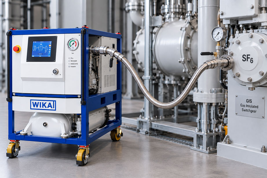
An SF₆ switchgear system has been filled to the specified gas condition, the filling pressure or gas density is correct, and the system valve is closed. The actual filling process is now complete – but the service process is not. Between the gas source, filling equipment and the system, there is still a service line filled with SF₆. Depending on the hose length, internal diameter, couplings and pressure, a surprisingly relevant quantity of gas can remain trapped inside it.
If the gas cylinder is simply closed at this point and the hose is then disconnected, the SF₆ trapped inside the hose is effectively treated as a loss. Self-closing couplings significantly reduce gas release during disconnection, but they do not remove the pressurised gas trapped inside the hose. The residual gas remains between the closed valves or couplings.
Particularly with long hoses, larger nominal diameters and higher filling pressures, the quantity of gas that must be recovered increases quickly. The visible filling hose is not the only relevant volume. Depending on the setup, the external service volume can also include pressure regulators, manifolds, adapters, coupling cavities, measuring connections and parts of the service equipment.
The most important rule is therefore: After filling, the gas compartment of the system must first be safely isolated. The SF₆ trapped outside the system is then recovered or transferred into a designated gas volume in accordance with the specified service procedure. The couplings should only be disconnected once the service line has been sufficiently depressurised or evacuated.
Why does SF₆ remain in the hose after filling?
During filling, the service line forms a continuous gas path between the gas source and the gas compartment of the system. As soon as the valves are opened, not only the switchgear but also the entire line volume between them is under gas pressure.
Once the specified condition has been reached and the system valve is closed, the system is separated from the service setup. However, the gas inside the external line does not disappear. It remains in the hose, valves, couplings and other cavities.
The amount of SF₆ contained there is determined primarily by three variables:
- the geometric internal volume of the service line,
- the absolute gas pressure at the moment of isolation,
- the gas temperature.
The real-gas behaviour must also be taken into account. For approximate estimates at moderate pressures, pressure-volume relationships can be used. For accurate gas inventories, however, the actual gas conditions or the information supplied by the service equipment should be used.
| Part of the service setup | May contain SF₆ after filling? | Influence on residual gas quantity |
|---|---|---|
| Filling hose | Yes | Often the largest single external volume |
| Self-closing coupling | Yes, within the internal dead volume | Small, but present during every service operation |
| Adapter | Yes | Depends on design and quantity |
| Valve/manifold block | Yes | Can become relevant in complex setups |
| Pressure regulator and fittings | Depending on setup | Additional enclosed volume |
| System gas compartment | Separate once the system valve is closed | Should not be unintentionally depressurised again after servicing |
Calculating hose volume correctly
For a cylindrical hose, the geometric internal volume can be approximated using the following formula:
V = π × di² × L / 4
Where:
- V = internal volume of the hose,
- di = actual free internal diameter,
- L = hose length.
The term actual internal diameter is important. A nominal size such as DN 8 is not automatically mathematically identical to an exact free internal diameter of 8.00 mm. For an accurate gas inventory, the manufacturer’s data for the specific hose should therefore be used.
For an approximate assessment, however, it is useful to show how strongly the hose length affects the volume. If an internal diameter of 8 mm is assumed as an example, the following values result:
| Hose length | Assumed internal diameter | Geometric internal volume |
|---|---|---|
| 1 m | 8 mm | approx. 0.050 l |
| 3 m | 8 mm | approx. 0.151 l |
| 5 m | 8 mm | approx. 0.251 l |
| 10 m | 8 mm | approx. 0.503 l |
Half a litre of geometric volume does not initially sound like much. However, if the gas inside is at several bar absolute, the gas quantity corresponds to several times this volume when converted to ambient or reference pressure.
Why absolute pressure is decisive
For determining the gas quantity, gauge pressure alone is not sufficient; the absolute pressure is decisive. A displayed gauge pressure of 6 bar, for example, corresponds approximately to 7 bar absolute if the ambient pressure is around 1 bar.
For a simplified estimate at approximately the same temperature:
Vref ≈ Vhose × pabs / pref
This makes the effect clear: at 7 bar absolute, a hose contains approximately seven times the gas quantity of the same hose at around 1 bar absolute, provided that temperature and real-gas effects are assumed unchanged for this approximate calculation.
This is why even a relatively small filling hose can contain a relevant quantity of SF₆ after filling.
Practical example: 5 m DN 8-type hose
For a simplified calculation example, a filling hose is considered using the following assumptions:
- length: 5 m,
- assumed internal diameter: 8 mm,
- hose volume: approximately 0.25 l,
- pressure after filling: 7 bar absolute.
The geometric hose volume is:
V ≈ 0.251 l
If the gas quantity is approximately referenced to 1 bar absolute at the same temperature, the order of magnitude is:
Vref ≈ 0.251 l × 7 ≈ 1.76 l
The actual quantity depends on reference pressure, temperature and compressibility. However, the example clearly shows that several litres of gas referenced to ambient conditions can be trapped inside a hose with a geometric volume of only 0.25 litres after filling.
If such a residual quantity is simply released during every service operation, small individual losses accumulate across many switching operations, installations and years to form a significant total loss.
Include couplings, adapters and manifolds
In practice, the calculation does not end with the hose. A service line often consists of several components:
Gas source → pressure regulator → hose → adapter → manifold → coupling → system
Each of these components has an internal volume. With a compact setup, this may be small compared with the hose. However, with many adapters connected in series or large manifold blocks, the additional volume becomes increasingly relevant.
For this reason, short and direct service setups are not only mechanically clearer. They also reduce the volume that must be evacuated before filling and handled with low gas losses after filling.
Improvised chains of adapters are particularly unfavourable. In addition to extra volume, they create additional sealing points and therefore more potential leak paths. A direct adapter suited to the system connection is therefore usually the better solution.
What self-closing couplings do – and what they do not do
Self-closing SF₆ couplings are an essential part of a low-emission service system. When the connection is disconnected, the relevant valves close automatically so that gas compartments are not permanently open to the atmosphere.
However, they do not automatically solve the problem of a pressurised hose. If SF₆ is trapped between two closed self-closing valves, the gas remains enclosed.
This is even desirable as long as the line is intended to remain closed. It only becomes critical when the line is opened, dismantled, transported or connected to a different gas condition.
The correct distinction is therefore:
Self-closing couplings prevent uncontrolled gas release during coupling and uncoupling – gas recovery reduces the quantity of SF₆ remaining in the service volume.
The two functions complement each other but do not replace one another.
Recover residual gas in a controlled manner
After the system valve has been closed, the SF₆ trapped in the hose should be recovered through a designated gas path. The suitable method depends on the filling system and service equipment being used.
For extensive maintenance work, recovery is typically carried out using an SF₆ service unit or a modular evacuation and transfer system. The gas is extracted from the service volume and transferred into a suitable gas container.
For smaller service setups, an appropriately designed recovery system can also be used. The decisive point is that the gas path, permissible pressure range, valve positions and destination container are clearly defined.
| Method | Suitability | Important point |
|---|---|---|
| SF₆ service unit | Very suitable for complete service processes | Filling, recovery and, depending on the unit, purification in one system |
| Vacuum compressor + transfer unit | Suitable for modular service setups | Residual gas is transferred into a designated container |
| Controlled pressure equalisation into a designated gas volume | Only if explicitly provided for by the system and service concept | Pressure difference and final pressure limit the transferable gas quantity |
| Simply opening the hose to atmosphere | Not a suitable residual-gas strategy | SF₆ is completely lost |
The specific valve sequence always depends on the system, coupling arrangement and service unit. A general internet guide should therefore never replace the manufacturer’s work instructions.
Why simple pressure equalisation is not always sufficient
At first glance, it may seem obvious to simply allow the gas inside the hose to flow back into a container. However, this only works as long as a sufficient pressure difference exists.
As soon as the pressures equalise, the gas flow stops. Gas then remains inside the hose at the common final pressure. Nearly complete recovery is therefore not possible by simple pressure equalisation alone.
This is particularly clear with a gas cylinder. After a filling operation, the pressure in the gas cylinder may be considerably higher than in the service line. The gas in the hose will then not flow back automatically against the higher cylinder pressure. A suitable transfer or compressor system is required for this purpose.
Returning residual gas to the system gas compartment must also be compatible with the specified operating procedure. If additional gas from the hose is forced back into the system in an uncontrolled manner after the correct filling quantity has been reached, the final condition of the system can change.
Residual-gas handling should therefore already be part of the filling concept and should not be improvised only after the valves have been closed.
What residual pressure remains after recovery?
Gas recovery does not necessarily mean that no SF₆ molecules remain inside the hose afterwards. The decisive variable is the achievable absolute residual pressure.
If, for example, a 5 m hose with a geometric volume of approximately 0.25 l is evacuated from 7 bar absolute down to only a few millibar absolute, the remaining gas quantity is reduced by several orders of magnitude.
In simplified form, the remaining quantity follows:
n ∝ pabs × V / T
The lower the absolute residual pressure at the same volume and temperature, the smaller the remaining gas quantity.
For a technically suitable recovery system, the achievable residual pressure is therefore an important parameter. It gives a much better indication of the remaining gas quantity than simply stating that the “hose is empty”.
Distinguishing between pressure, temperature and gas density
Temperature-compensated gas density is commonly used in SF₆ switchgear. When emptying a filling hose, however, it is important to distinguish between the gas density in the system gas compartment and the instantaneous pressure in the service volume.
The pressure inside an enclosed hose volume changes with temperature. A hose isolated in a warm environment may show a lower pressure after cooling even though no gas has been lost. Conversely, the pressure rises when the gas is warmed.
A pressure change is therefore not automatically an indication of a leak.
For a quantitative gas balance, pressure, temperature and volume should be considered together. For higher accuracy requirements, real-gas properties must also be taken into account.
For the system itself, the manufacturer’s specified temperature-compensated target condition remains decisive after filling. The hose pressure after isolation must not be confused with this system target value.
Consider moisture and gas quality during servicing
SF₆ servicing is not only about reducing gas losses. The gas quality must also be maintained. A hose filled with air and moisture before filling can introduce foreign gas into the system. The service line is therefore evacuated according to the specified procedure before the gas compartment is opened.
After filling, the opposite situation applies: the hose now contains SF₆. If it is opened and then stored unsealed for an extended period, ambient air and moisture can enter the line again.
After servicing, connections should therefore be closed cleanly and protective caps installed. Before the next filling operation, the line is prepared again in accordance with the specified procedure.
Particular care is required when handling gas recovered from equipment in which switching operations, arcing or faults have occurred. Recovered gas may contain moisture, particles or decomposition products. It must therefore not automatically be treated as equivalent to unused gas.
Sensible operating sequence after filling
The exact valve sequence depends on the system and the equipment being used. However, the underlying technical principle can be structured clearly.
- Check the filling condition: Ensure that the specified gas condition of the system has been reached.
- Close the system valve: Isolate the gas compartment from the external service line.
- Close the gas source: Shut off the gas cylinder or filling supply.
- Identify the service volume: Include the hose, adapters, manifolds and other trapped volumes.
- Establish the recovery path: Configure the designated service or transfer equipment in accordance with the operating instructions.
- Recover the SF₆: Transfer the gas into the designated gas container or system.
- Monitor the residual pressure: Reach the specified final pressure according to the service procedure.
- Isolate the line: Shut off the recovery equipment.
- Check the pressure condition: Before disconnecting, ensure that no unexpected overpressure remains.
- Disconnect the coupling: Release the self-closing connection in a controlled manner.
- Close the connections: Install protective caps.
- Check the system: Inspect the service connection and gas compartment for leak tightness and correct condition in accordance with the maintenance plan.
It is important not to clarify an uncertain valve position by opening valves experimentally. With SF₆ service setups, the gas path should be clearly understood before work begins.
If the hose remains pressurised despite recovery
If an unexpectedly high pressure remains in the line after the specified evacuation process, the cause should be investigated systematically.
Possible causes include a closed intermediate valve, a self-closing coupling that is not opening the gas path, an incorrect valve position on the service equipment or a heavily restricted flow cross-section. A pressure gauge may also be located in a section that is isolated by a valve from the hose section actually being evacuated.
With long hoses and small cross-sections, some time may also be required for the pressure to equalise along the complete line.
Another possible cause is a change in temperature. If an isolated hose section becomes significantly warmer after evacuation, the pressure of the remaining gas can increase again.
Before a hose system is opened or dismantled, it must therefore be clear which section has actually been depressurised.
Practical example on a GIS
A gas-insulated switchgear system is topped up via an SF₆ hose several metres in length. The service setup consists of a gas source, pressure regulator, hose, adapter and self-closing coupling.
Once the specified condition has been reached, the system valve is closed first. The system is therefore isolated from the service setup again. The gas source is then closed.
At this point, however, the hose is still at approximately the previous filling pressure. If the self-closing coupling were disconnected immediately, it would indeed close the system gas compartment, but the SF₆ inside the external service volume would still remain present.
The hose is therefore connected to a gas container through the designated service equipment. The trapped SF₆ is recovered until the required residual pressure has been reached. Only then is the service line disconnected from the system.
This example shows why a self-closing coupling and residual-gas recovery perform two different tasks: the coupling allows the connection to be disconnected with low gas loss. The service equipment first reduces the amount of gas that is still present inside this connection.
Common errors
Disconnecting immediately after closing the system
This ignores the gas volume stored inside the hose. The service line may still contain pressurised SF₆.
Assuming that a self-closing coupling means the hose is empty
The coupling closes the gas path. It does not evacuate the gas trapped inside the line.
Considering only the hose length
Internal diameter and pressure have an equally important influence on the gas quantity. Adapters, couplings and manifolds also form part of the service volume.
Calculating with gauge pressure instead of absolute pressure
Gas-quantity calculations require absolute pressure. Particularly at operating pressures of several bar, confusing the two causes a relevant error.
Trying to force residual gas directly back into the gas cylinder
If the cylinder pressure is higher than the hose pressure, there will be no automatic return flow. Suitable transfer equipment is required for controlled transfer.
Reopening the system valve in an uncontrolled manner for residual-gas handling
This can alter the correctly adjusted gas condition of the system. Returning gas to the gas compartment must only form part of an approved service procedure.
Storing the hose open after servicing
This allows air, moisture and dirt to enter the system. Connections should be protected and the service line correctly prepared again before the next use.
Accepting residual gas as an unavoidable service loss
Particularly for recurring work, the residual gas quantity should be minimised by design and recovered using suitable equipment.
Suitable SF₆ components at ICS Schneider
ICS Schneider Messtechnik offers SF₆ components for filling, evacuation, gas recovery and gas management.
WIKA GCH-08 and GCH-20 hoses are intended for filling and evacuating SF₆ gas compartments. They are designed for both pressure and vacuum operation and use self-closing valves or couplings. Different nominal sizes are available depending on the required gas flow and system connection.
For smaller or modular recovery tasks, the WIKA GVC-10 is available, among other options. Together with a suitable transfer unit, SF₆ can be extracted from gas compartments or service volumes and transferred into a designated gas container.
For more extensive service work, units from the WIKA GPU platform are available. Depending on the version, they combine functions for filling, recovery, evacuation and gas purification in a single system.
SF₆ hoses and gas filling sets at ICS Schneider
SF₆ service equipment at ICS Schneider
Further reading: Evacuating SF₆ filling hoses before filling
Conclusion
After filling an SF₆ system, the filling hose is not automatically empty. Once the system valve and gas source are closed, the SF₆ remains trapped inside the external service line.
The relevant residual gas quantity depends on the hose and dead volume, absolute pressure and temperature. A long hose or an unnecessarily complex adapter chain can therefore contain significantly more gas than might be expected from its external appearance.
Self-closing couplings are essential for low-loss gas handling, but they do not replace residual-gas recovery. They close the gas path during disconnection, while a service or transfer system reduces the amount of SF₆ previously stored in the hose.
For a clean service process, the system gas compartment is therefore isolated first. The external line is then recovered in a controlled manner or evacuated down to the specified residual pressure. Only afterwards are the couplings disconnected and the connections sealed.
Anyone who also minimises hose length, nominal size, number of adapters and dead volume during the planning stage reduces both the time required for evacuation and recovery and the quantity of SF₆ that has to be handled during each individual service operation.
FAQ on SF₆ residual gas in filling hoses
Is the SF₆ filling hose empty after the system valve has been closed?
No. The gas in the external hose volume initially remains trapped. The system valve and coupling only separate the different gas volumes from one another.
How do you calculate the internal volume of a filling hose?
Approximately using V = π × d² × L / 4. The actual internal diameter and hose length must be used.
Does DN 8 automatically mean an internal diameter of exactly 8 mm?
No. The nominal size is not necessarily identical to the actual free internal diameter. Accurate calculations require the data for the specific hose.
Why does pressure influence the residual gas quantity?
At the same hose volume, a higher absolute pressure means that more gas is contained in the hose. A small geometric volume can therefore hold a relevant gas quantity at several bar.
Must absolute pressure be used for the calculation?
Yes. Gas-law calculations use absolute pressures, not only the gauge pressure displayed on a pressure gauge.
Does a self-closing coupling prevent every SF₆ loss?
It significantly reduces gas release during disconnection and automatically closes the gas path. However, it does not remove the SF₆ trapped inside the hose.
What happens to the SF₆ inside the hose?
It should be recovered in accordance with the specified service procedure into a suitable gas container or via an SF₆ service or transfer system.
Can the residual gas simply flow back into the gas cylinder?
Only if there is a suitable pressure difference and a gas path intended for this purpose. In many practical situations, the cylinder pressure is higher, so suitable transfer equipment is required for defined recovery.
Can the residual gas be returned to the system?
Only if the specific system and service procedure provide for this. Reopening the system valve in an uncontrolled manner can alter the previously adjusted filling condition.
Why should SF₆ hoses not be unnecessarily long?
A longer hose has a larger internal volume. This increases both the amount of air that must be evacuated before filling and the amount of SF₆ that must be recovered after filling.
Why are unnecessary adapters unfavourable?
They increase dead volume, the number of sealing points and potential leak paths. At the same time, the gas path becomes more complex.
What does residual pressure after recovery mean?
Even after evacuation, a small quantity of gas may remain in the hose. The absolute residual pressure describes how strongly this quantity has been reduced compared with the original operating condition.
Does a filling hose have to be evacuated again after servicing?
Before a later filling operation, the service line must be prepared again in accordance with the specified procedure so that no air or moisture is introduced into the SF₆ gas compartment.
Can temperature change the pressure in an isolated hose?
Yes. If a closed gas volume heats up or cools down, its pressure changes even without gas loss. A pressure change is therefore not automatically a leak.
Which WIKA hoses are intended for SF₆ service?
For suitable applications, WIKA GCH-08 and GCH-20 hoses are available, among others. The nominal size is selected according to the service task, connection and required gas flow.
Which device is suitable for SF₆ recovery?
Depending on the scope of work and system volume, modular components such as the GVC-10 with a transfer unit or complete service units from the WIKA GPU platform can be used.