


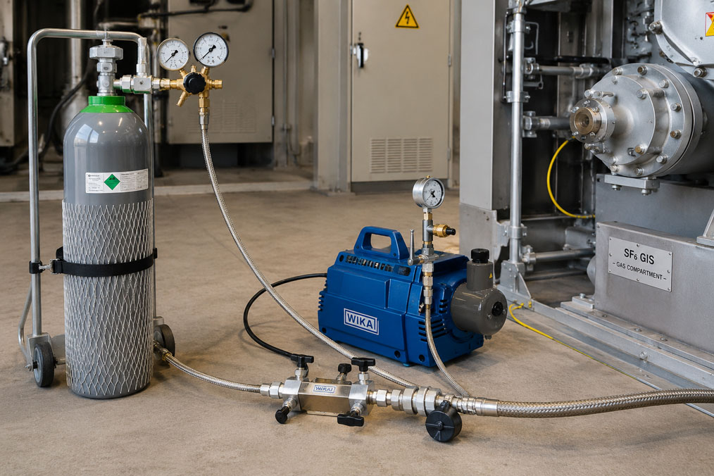
When topping up an SF₆ gas-insulated switchgear system, attention is often focused primarily on achieving the correct filling pressure. However, the quality of the filling process also depends on what is present inside the filling hose, adapters, valve manifolds and pressure regulators before the switchgear coupling is opened.
A hose that has not been evacuated contains ambient air. When the connection to the switchgear is opened, nitrogen, oxygen and water vapour are introduced into the gas compartment. Particularly with small gas compartments or long hoses, this proportion of foreign gas may be significant in relation to the quantity of SF₆ already present.
The correct procedure is therefore not simply to purge the hose with SF₆ and release the gas into the atmosphere. The complete service line is connected gas-tight, evacuated, tested for vacuum stability and only then pressurised with SF₆ in a controlled manner.
Suitable components can be found in the ICS category SF₆ Hoses and Gas Filling Sets. Vacuum pumps, transfer units and complete gas-management systems are grouped under SF₆ Service Equipment.
Table of Contents
- Why is air inside the filling hose problematic?
- How does moisture enter the gas compartment?
- Estimating hose volume and the proportion of foreign gas
- Distinguishing between evacuation, purging and recovery
- Topping up or complete refilling?
- Planning a technically suitable filling arrangement
- Checking hoses and couplings before use
- Safe operating and valve sequence
- Correctly assessing the vacuum hold test
- Filling the system with SF₆ in a controlled manner
- Handling residual gas in the hose with low emissions
- Selecting couplings, valves and adapters
- Correctly connecting the gas cylinder and pressure regulator
- Assessing gas quality after filling
- Checking the leak tightness of the measuring and filling line
- Documenting the filling process traceably
- Practical example: Topping up a small GIS unit
- Typical errors when topping up SF₆
- Which products and solutions are suitable?
- Conclusion
- Frequently asked questions
Why is air inside the filling hose problematic?
SF₆ is used as an insulating and switching gas because of its electrical properties. However, connecting a suitable gas cylinder does not automatically mean that the intended gas filling consists exclusively of high-quality SF₆.
Before filling, the service line may contain:
- ambient air,
- water vapour,
- residual gas from a previous application,
- nitrogen from a test or purging operation,
- oil or solvent vapours,
- particles and abrasion,
- decomposition products from previously serviced equipment.
If the hose is opened without evacuation, its entire internal volume becomes part of the gas compartment. The air does not disappear; it is merely mixed with the existing or newly introduced SF₆.
Possible consequences include:
- reduced SF₆ purity,
- increased oxygen and nitrogen content,
- additional moisture ingress,
- different gas density at the same pressure,
- more difficult assessment of subsequent gas analyses,
- inconsistent results between filling operations,
- long-term deterioration of gas quality.
The filling pressure alone cannot reliably detect this error. A gas mixture can reach the specified pressure even though its SF₆ content and moisture level do not meet the requirements.
How does moisture enter the gas compartment?
Moisture does not enter an SF₆ system only in the form of visible water droplets. Normal ambient air already contains water vapour. In addition, the internal surfaces of hoses, seals and dead spaces can absorb moisture and release it again later.
Typical sources of moisture include:
- hoses stored open without protective caps,
- long-term storage in humid rooms or vehicles,
- condensation following significant temperature changes,
- cleaned but insufficiently dried adapters,
- permeable or unsuitable hose materials,
- moist compressed air used for blowing out components,
- valve manifolds and measuring connections that have not been evacuated,
- residual moisture after opening a gas compartment.
During evacuation, free gas is removed. Moisture bound to surfaces may, however, be released with a delay. In addition to achieving a sufficiently low final pressure, the evacuation time and vacuum hold test are therefore important.
If the pressure rises slowly after the vacuum pump has been isolated, this may indicate moisture outgassing. A rapid or continuous pressure rise is more likely to indicate a leak or a section of the system that has not been fully opened or evacuated.
Estimating hose volume and the proportion of foreign gas
The internal volume of a hose can be approximated using:
V = π × di² × L / 4
Where:
- V: internal hose volume,
- di: actual internal diameter,
- L: hose length.
For example, a hose with an assumed internal diameter of 8 mm and a length of 5 m has an approximate internal volume of:
V ≈ 0.25 litres
The nominal size of a hose does not necessarily correspond exactly to its free internal diameter. The manufacturer’s data for the specific hose version must therefore be used for an accurate calculation.
The extent to which this air volume affects the filling depends on the gas-compartment volume and the absolute final pressure. For a simplified estimate, the proportion of foreign gas can be assessed using the pressure-volume relationships.
Example:
- air volume inside the hose: 0.25 l at 1 bar absolute,
- gas compartment: 30 l,
- filling pressure: 6 bar absolute.
The idealised calculated air content is then approximately 0.14%. In is then approximately 0.14%. In a gas compartment of only 5 l, the same hose would introduce an air content of approximately 0.8%.
The example demonstrates that the smaller the gas compartment and the larger the connected service volume, the more important it is to evacuate the hose, valve manifold, pressure regulator and adapters completely.
Distinguishing between evacuation, purging and recovery
Evacuation
During evacuation, air, nitrogen and moisture are removed from an empty hose or gas compartment using a vacuum pump. This is the preferred method for preparing the filling system.
Purging
During purging, a gas is passed through the line to displace the gas previously contained inside it. A single pressurisation does not completely remove the air, but merely dilutes it.
Purging with SF₆ must not result in the purging gas being released into the atmosphere. If purging is required according to the manufacturer’s instructions, the discharged gas must be collected or routed into a suitable recovery system.
Recovery
During recovery, existing SF₆ is extracted from a hose, gas compartment or piece of equipment and transferred into a suitable storage vessel. This does not use an ordinary vacuum-pump arrangement intended for removing air, but equipment specifically designed for SF₆ transfer.
A vacuum pump used for filling preparation and a vacuum compressor used for SF₆ recovery therefore perform different tasks and must not be confused with one another.
Topping up or complete refilling?
The required evacuation depends on the work that has been performed on the system.
Topping up a closed gas compartment
If the gas compartment has not been opened and still contains SF₆, the complete system is not evacuated. Only the newly connected service volumes are evacuated:
- filling hose,
- pressure regulator or filling assembly,
- valve manifold,
- adapters,
- measuring lines,
- where applicable, the coupling space up to the closed system valve.
Refilling after opening the gas compartment
If the system has been opened, vented or serviced internally, the gas compartment contains ambient air. In this case, both the gas compartment and the complete connected service line must be evacuated in accordance with the system instructions.
Evacuating an opened gas compartment requires a pumping capacity appropriate for the system volume, suitable vacuum measuring equipment and a documented vacuum hold test.
Filling after gas recovery
If SF₆ has merely been recovered from a closed system, it must be determined whether the gas compartment was subsequently opened or pressurised with air or nitrogen. This determines whether complete evacuation is required.
Planning a technically suitable filling arrangement
A typical filling arrangement consists of:
SF₆ gas cylinder → cylinder valve → pressure regulator or filling set → gas-tight SF₆ hose → valve or manifold block → self-closing system coupling → SF₆ gas compartment
An additional vacuum connection is required for evacuation:
Vacuum pump → vacuum hose or SF₆ service line → manifold block → complete filling hose up to the closed system valve
The manifold must provide clear separation between the gas source, vacuum pump and system. Incorrect operation that could allow SF₆ to flow towards the vacuum pump or ambient air to enter the system must be prevented by suitable valves, markings and working instructions.
The arrangement should be kept as compact as possible. Every additional adapter increases:
- the volume to be evacuated,
- the number of potential leak points,
- the residual gas volume after filling,
- the risk of an incorrect valve position,
- the time required for evacuation and pressure equalisation.
Checking hoses and couplings before use
The entire service line must be checked before every filling operation.
The visual and functional inspection should include in particular:
- clear identification of the hose,
- the permissible pressure and vacuum range,
- the correct nominal size and connection design,
- undamaged stainless-steel sheathing or protective braiding,
- absence of kinks, crushing or abrasion marks,
- clean and dry coupling surfaces,
- undamaged seals,
- correctly functioning self-closing valves,
- available protective caps,
- a valid inspection or maintenance status.
A hose that was previously used for another gas, contaminated SF₆ or equipment containing decomposition products must not be used for a high-quality refill without assessment and, where necessary, cleaning.
Open connections must not be placed on the floor, on dirty tool trolleys or in humid areas. Protective caps should only be removed immediately before connection and must be refitted after use.
Safe operating and valve sequence
The exact valve sequence depends on the switchgear, filling set and service equipment. The following sequence therefore describes the basic technical principle and does not replace the manufacturer’s instructions.
- Check the work authorisation: Secure the system, identify the gas compartment and verify the target filling data.
- Keep the gas source closed: The cylinder valve and filling valve initially remain closed.
- Keep the system valve closed: Connect the coupling without opening the gas compartment.
- Connect the complete service line: Install the hose, adapters, manifold and vacuum connection gas-tight.
- Open the evacuation path: Open only the valves between the vacuum pump and service line.
- Evacuate the filling line: Pump until the specified final pressure or evacuation time has been achieved.
- Isolate the vacuum pump: Separate the service line from the pump inlet.
- Perform the vacuum hold test: Observe the pressure trend during the specified hold period.
- Open the gas source in a controlled manner: Slowly pressurise the evacuated line with SF₆.
- Open the system valve: Only after the service line has been filled with clean SF₆.
- Fill SF₆ slowly: Monitor the filling pressure, gas density, temperature and transferred gas quantity.
- Close the system valve: Once the target condition has been reached, isolate the gas compartment first.
- Close the gas source: Close the cylinder valve and filling assembly.
- Handle residual gas: Recover the SF₆ remaining inside the hose or transfer it into the system using an approved procedure.
- Disconnect the couplings: Only after depressurisation or residual-gas recovery.
- Seal the connections: Fit the protective caps and check the system for leaks.
An unclear valve position must not be investigated by trial opening while the line is pressurised. A simple flow diagram of the specific arrangement should be available before work begins.
Correctly assessing the vacuum hold test
Achieving a low pressure alone does not prove that the service line is leak-tight and dry. After evacuation, the connection to the vacuum pump is closed and the pressure trend is observed.
Possible observations:
| Pressure trend | Possible cause | Suitable check |
|---|---|---|
| Pressure remains almost stable | Service line is probably sufficiently leak-tight and outgassed | Check the manufacturer’s acceptance criterion and measurement uncertainty |
| Rapid pressure rise | Leak, open valve or defective coupling | Check connections and valve positions |
| Slow, decreasing pressure rise | Outgassing of moisture or trapped gases | Extend the evacuation time and repeat the test |
| Final pressure is not achieved | Leak, insufficient pump capacity, contaminated line or incorrect measuring arrangement | Check the arrangement section by section |
| Measured value jumps or is unstable | Unsuitable vacuum gauge or unfavourable measuring connection | Check the measuring range and position of the vacuum gauge |
The final pressure, evacuation time, permissible pressure rise and hold time are system-specific. The maximum performance of the vacuum pump must not be confused with the acceptance criterion required by the switchgear manufacturer.
A vacuum hold test can reveal leaks and outgassing. However, it does not automatically replace a leak test of the system when it is subsequently pressurised with SF₆.
Filling the system with SF₆ in a controlled manner
Following successful evacuation, the service line is first pressurised with SF₆ in a controlled manner. Only then is the connection to the gas compartment opened.
The following points must be considered during filling:
- the filling pressure or target gas density specified by the system manufacturer,
- reference and ambient temperature,
- maximum permissible filling pressure,
- slow pressure equalisation,
- permissible differential pressure across couplings and valves,
- correct position of all shut-off valves,
- quantity of gas inside the cylinder,
- where applicable, the scale reading and filling-mass balance,
- condition of the gas-density monitor or gas-density sensor.
The pressure inside a closed gas compartment changes with temperature. A cold system must therefore not be filled solely up to a pressure-gauge value specified for a higher reference temperature.
The manufacturer’s specifications for temperature compensation or the required standardised gas density are decisive. Overfilling must not subsequently be corrected by uncontrolled venting into the atmosphere.
The filling valve is opened slowly. Rapid pressurisation can place mechanical components under stress, cause temperature changes and make accurate dosing more difficult.
Handling residual gas in the hose with low emissions
After the system and cylinder valves have been closed, the filling hose still contains SF₆. The quantity depends on the hose volume and residual pressure.
This gas must not be treated as an unavoidable loss. Suitable options include:
- recovery into a gas cylinder,
- extraction using an SF₆ transfer or service unit,
- controlled pressure equalisation into the gas compartment, provided this is permitted by the system manufacturer,
- transfer into a suitable collection vessel.
Self-closing couplings limit the release of gas during disconnection. However, they do not automatically remove all the pressurised gas trapped inside the hose.
Short hoses and small dead volumes reduce both the evacuation effort and the quantity of SF₆ that must be recovered after filling.
Selecting couplings, valves and adapters
Arbitrary hydraulic, refrigeration or compressed-air couplings must not be used for SF₆. The components must be suitable for vacuum, filling pressure, SF₆ and any decomposition products that may be present.
Important selection criteria include:
- vacuum and pressure resistance,
- tested gas tightness,
- SF₆-resistant materials and seals,
- self-closing valve function,
- clearly defined nominal size,
- suitable system and cylinder connections,
- low dead volume,
- safe operation while wearing gloves,
- protective caps for transport and storage,
- resistance to possible decomposition products.
Chains of adapters should be avoided. Several adapters installed in series increase dead volume and the risk of leakage and make it more difficult to verify the valve positions clearly.
Couplings must not be connected or disconnected while subjected to an impermissibly high differential pressure. The technical data for the specific version are decisive.
Correctly connecting the gas cylinder and pressure regulator
Before connecting the SF₆ gas cylinder, at least the following points must be checked:
- clear identification and gas content,
- gas quality or certificate,
- filling quantity and available supply,
- condition of the cylinder valve and thread,
- suitable connection for the pressure regulator,
- permissible cylinder and outlet pressure,
- clean and dry sealing surfaces,
- safe positioning and securing of the cylinder,
- valid inspection status of the vessel.
The pressure regulator and filling set are part of the service line that must be evacuated. Evacuating the hose alone is insufficient if air remains inside the regulator, manifold or adapters.
The cylinder valve must not be opened while an uncontrolled path to the vacuum pump or atmosphere is present. Before releasing the gas, the vacuum and venting paths must be reliably isolated.
Assessing gas quality after filling
A complete gas analysis is not required in every case after a simple, small top-up. The decision depends on the system manufacturer, the scope of maintenance, the initial condition and the operational requirements.
A gas-quality test is particularly advisable:
- after opening and evacuating a gas compartment,
- after extensive repairs,
- if air or moisture ingress is suspected,
- following an unusual vacuum hold test,
- when using recovered or treated gas,
- after arcing or switching events that may have caused decomposition,
- if the history of the existing gas is unclear,
- when limits for purity and moisture must be verified.
Typical analysis parameters include:
- SF₆ purity or gas composition,
- moisture or dew point,
- decomposition products,
- where applicable, oxygen or foreign-gas content.
A pressure or density measurement does not replace a gas-quality analysis. It indicates the quantity or density of gas present, but not its composition reliably.
Checking the leak tightness of the measuring and filling line
The leak-tightness check covers both the temporary service line and the system connection after filling.
The following components must be checked:
- hose couplings,
- adapters and fittings,
- valve stems,
- pressure-regulator connections,
- the switchgear service coupling,
- protective and sealing caps,
- system valves that have been closed again after the work.
A successful vacuum hold test before filling is an important indication of the leak tightness of the service line. An appropriate SF₆ leak test may additionally be required after filling.
The leak-detection agents, test procedures and permissible leakage rates must be suitable for the system. Liquid leak-detection agents must not be allowed to enter couplings or valves uncontrollably.
Documenting the filling process traceably
Complete documentation should include at least:
- the system, switchgear panel and gas-compartment designation,
- the date, location and responsible personnel,
- the work authorisation and proof of qualification,
- the reason for filling or topping up,
- the gas cylinder and gas batch used,
- the quality or certificate of the SF₆,
- the filling set and hose identification used,
- the hose length and nominal size,
- the adapters and couplings used,
- the final pressure achieved during evacuation,
- the evacuation and hold time,
- the pressure rise during the vacuum hold test,
- the initial and final pressure or gas density,
- the temperature during filling,
- the transferred gas mass,
- the treatment of residual gas inside the hose,
- the result of the final leak-tightness test,
- where applicable, the gas-analysis results,
- identified deviations and follow-up actions.
A documented gas mass supports the emissions balance and helps distinguish subsequent pressure losses from normal temperature-related changes.
Practical example: Topping up a small GIS unit
The gas-density monitor on a gas-insulated switchgear system has indicated a low gas condition. After a leak test and elimination of the cause, the closed gas compartment is to be topped up.
The gas compartment has not been opened. The existing SF₆ therefore remains inside the system. Only the filling set, hose, manifold, adapters and coupling chamber up to the closed system valve are evacuated.
The planned arrangement is:
SF₆ cylinder → WIKA GFK-10 filling set → GCH-08 hose → manifold with vacuum connection → self-closing system coupling → closed gas compartment
The work is performed in the following steps:
- The gas compartment and target filling density are identified using the system documentation.
- The SF₆ cylinder is secured in position and the cylinder valve remains closed.
- The filling set, hose and system coupling are connected gas-tight.
- The service line is evacuated using a GVP-10 vacuum pump.
- After reaching the specified vacuum, the pump is isolated.
- During the vacuum hold test, the pressure remains within the specified limit.
- The vacuum path is closed and the evacuated line is slowly pressurised with SF₆.
- The system valve is opened and SF₆ is introduced in a controlled manner until the temperature-compensated target gas density is reached.
- The system valve is closed first, followed by the cylinder valve.
- The SF₆ remaining inside the hose is transferred into a suitable recovery system.
- The coupling is disconnected and sealed, and the system connection is checked for leaks.
- The filling quantity, temperature, gas density and test result are documented.
If the 5 m hose had not been evacuated, its entire air and moisture content could have entered the relatively small gas compartment. The gas-density monitor would not automatically have detected this foreign-gas ingress.
Typical errors when topping up SF₆
| Error | Possible consequence | Suitable corrective action |
|---|---|---|
| Filling hose not evacuated | Air and water vapour enter the gas compartment | Evacuate the complete service line before releasing the gas |
| Only the hose is evacuated, but not the regulator and adapters | Residual air remains in additional dead volumes | Include the entire connected gas path |
| SF₆ is discharged into the atmosphere for purging | Unnecessary emissions and gas loss | Evacuate the line or recover the purging gas completely |
| Vacuum pump confused with recovery equipment | Unsuitable gas transfer and possible contamination | Plan filling preparation and SF₆ recovery separately |
| No vacuum hold test performed | Leaks or outgassing remain undetected | Isolate the service line and document the pressure trend |
| Unnecessarily long hose used | Larger air and residual-gas volume | Select the shortest technically suitable hose length |
| Open coupling placed on a dirty floor | Particle and moisture ingress | Use protective caps and store connections cleanly |
| System valve opened before pressurising the hose with SF₆ | Loss of vacuum or ingress of foreign gas | Evacuate the service line first and fill it with SF₆ |
| Filling set solely according to the current pressure-gauge reading | Underfilling or overfilling due to temperature influence | Observe the temperature-compensated target gas density |
| Hose disconnected immediately after filling | Pressurised SF₆ trapped inside the hose is released | Recover the residual gas or equalise it using an approved procedure |
| Hydraulic hose used instead of an SF₆ hose | Insufficient gas tightness and unsuitable materials | Use tested SF₆ hoses that are vacuum- and pressure-resistant |
| Gas quality assessed only on the basis of pressure | Air or moisture ingress remains undetected | Analyse purity, moisture and decomposition products where required |
Which products and solutions are suitable?
WIKA GCH-08 and GCH-20 SF₆ hoses
The WIKA GCH-08 and GCH-20 hoses are designed for filling and evacuating SF₆ gas compartments. They are vacuum- and pressure-resistant and are helium leak-tested.
The stainless-steel construction with additional stainless-steel braiding protects the hose against external damage. Self-closing valves and couplings support low-emission connection and disconnection.
DN 8 is typically suitable for compact filling and service arrangements. DN 20 may be appropriate for larger gas compartments and higher required gas flow rates. The nominal size, length and connections must be matched to the service equipment and system.
WIKA GFK-10 SF₆ filling set
The WIKA GFK-10 filling set is used for the controlled filling and topping up of SF₆ gas from a gas cylinder.
The required filling pressure is set at the pressure regulator. Two pressure gauges allow the inlet and outlet pressure to be monitored. The connection to the system is made using suitable self-closing valves and an SF₆ filling hose.
For filling without introducing air, the gas path inside the filling set must also be included in the evacuation concept.
WIKA GVP-10 portable vacuum pump
The WIKA GVP-10 is used to evacuate air or nitrogen when preparing SF₆ gas compartments and service lines for filling.
The pump provides a suction capacity of up to 10 m³/h and can achieve a final pressure of no more than 0.02 mbar absolute. An integrated oil-return barrier prevents pump oil from flowing back into the evacuated gas path when the pump stops.
The achievable final pump pressure is not automatically the acceptance criterion required for the switchgear system. The specifications of the system manufacturer remain decisive.
WIKA GCx-08 and GCx-20 connecting components
The GCx-08 and GCx-20 connecting components include valves, coupling valves, adapters, protective caps and connections for different SF₆ components.
They enable vacuum- and pressure-resistant adaptation between service equipment, hoses, analysis instruments and switchgear. Suitable original connections avoid long adapter chains and additional dead volumes.
WIKA GPU service units
The WIKA service units of the GPU-B and GPU-S series combine several operations, such as evacuation, filling, recovery, filtration and treatment, in one system.
They are particularly suitable when larger gas compartments are serviced regularly or when SF₆ recovery and treatment are required in addition to topping up.
A complete service unit reduces the need for temporary connections and enables controlled handling of the gas remaining inside the hose or system.
WIKA GA11 SF₆ gas analyser
The WIKA GA11 is used to assess SF₆ gas quality. Depending on the configuration, it can determine moisture, gas purity or gas composition and decomposition products.
After analysis, the measuring gas can be returned to the tested gas compartment, transferred to an external gas cylinder or collected in a gas recovery bag. This also enables gas-quality testing to be performed with low emissions.
ICS Schneider Messtechnik provides support in selecting SF₆ hoses, filling sets, couplings, vacuum pumps and service equipment, as well as in planning evacuation, filling, recovery and documentation procedures.
Conclusion
Before connection, an SF₆ filling hose contains ambient air and therefore also moisture. If this volume is not evacuated, it enters the gas compartment when the system valve is opened.
Particularly with small gas compartments, long hoses and extensive adapter arrangements, the proportion of foreign gas introduced may be significant. Not only the visible hose, but also the pressure regulator, manifold, valves and adapters must be included in the evacuation process.
The preferred procedure is gas-tight evacuation followed by a vacuum hold test. Purging with SF₆ and releasing it into the atmosphere is not an appropriate alternative.
After successful testing, the evacuated line is first pressurised with SF₆ in a controlled manner. Only then is the system valve opened and the equipment slowly filled to the temperature-compensated target gas density.
The SF₆ trapped inside the hose after filling must be recovered or transferred into the gas compartment using an approved procedure. Self-closing couplings reduce emissions but do not replace residual-gas treatment.
Vacuum- and pressure-resistant SF₆ hoses, suitable couplings, an appropriate filling set and a vacuum pump designed for filling preparation together form a technically correct filling line.
Frequently asked questions about evacuating SF₆ filling hoses
Must an SF₆ filling hose be evacuated before every filling operation?
Yes, if the hose may have contained ambient air since its last use. After storage, transport or changing a connection, it should also be assumed that air and moisture are present.
Is it sufficient to purge the hose briefly with SF₆?
Brief pressurisation merely dilutes the existing air. Purging must also not result in SF₆ emissions. Evacuation is normally the more suitable method.
Must the complete gas compartment also be evacuated when topping up?
No, provided that the gas compartment has remained closed and still contains SF₆. In this case, only the newly connected service volumes are evacuated.
When must the complete gas compartment be evacuated?
After the gas compartment has been opened or vented and following work during which air has entered the system. The specific requirements are defined by the system manufacturer.
Why is a vacuum hold test required?
It indicates whether the evacuated line is sufficiently leak-tight or whether leaks or outgassing moisture are present. Briefly reaching a low pressure is not sufficient.
What vacuum must be achieved?
The final pressure, hold time and permissible pressure rise are specific to the system and procedure. The manufacturer’s specifications for the switchgear and service equipment apply.
Can an ordinary workshop vacuum pump be used?
Filling preparation requires a suitable vacuum pump with appropriate gas-tight connections, backflow protection and a sufficient final pressure. Ordinary pumps or contaminated hoses can introduce additional contamination into the service line.
Can the same pump also recover SF₆ from the system?
Not automatically. A vacuum pump for removing air or nitrogen performs a different function from an SF₆ vacuum compressor or recovery unit.
Why must the pressure regulator also be evacuated?
The pressure regulator contains its own cavities and gas passages. If these remain filled with air, the air enters the filling line despite the hose having been evacuated.
What happens to the SF₆ inside the hose after filling?
It is recovered into a suitable vessel or by means of a service unit. Alternatively, pressure equalisation into the gas compartment may be performed if approved by the system manufacturer.
Can the gas-density monitor detect an air content?
A gas-density monitor primarily measures the temperature-compensated gas density. It does not automatically determine the SF₆ purity or moisture content.
When is a gas analysis advisable after filling?
In particular after opening the gas compartment, if air or moisture ingress is suspected, following an unusual evacuation result or when recovered gas has been used.