


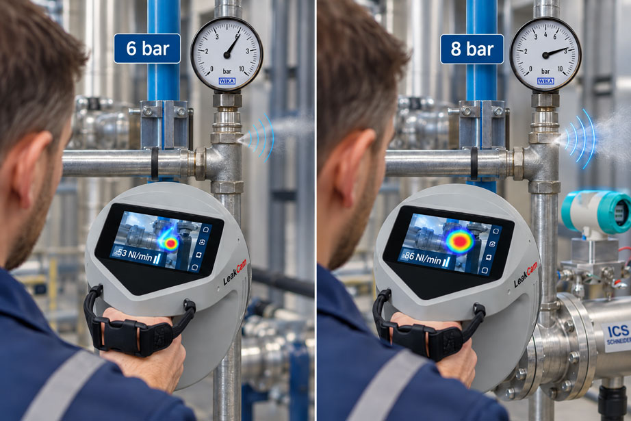
During a compressed-air audit, a leak rate of 63 Nl/min is measured at a leaking fitting. A few weeks later, the same point is checked again and the measuring instrument shows 86 Nl/min. At first glance, the leak appears to have become significantly larger. However, a look at the measurement records reveals that the first measurement was carried out at a network pressure of approximately 6 bar, while the second was performed at around 8 bar.
The two values are therefore not directly comparable. A real leak does not have a completely pressure-independent leakage rate. The greater the pressure difference between the compressed-air network and the surrounding atmosphere, the more air can escape through the same opening. A higher measured leakage rate can therefore simply be the result of a higher operating pressure – even if the mechanical condition of the leak has not changed at all.
The unit itself often causes additional confusion. If a leakage rate is specified in Nl/min or Nm³/h, the gas volume has already been referenced to defined temperature and pressure conditions. However, this standardisation answers a different question from referencing the measurement to a specific network pressure. A leakage rate of 80 Nl/min at 8 bar and a leakage rate of 60 Nl/min at 6 bar may both refer to the same gas reference conditions, but they were generated under different operating conditions at the leak itself.
The most important rule is therefore: For reliable before-and-after comparisons, both the unit and its reference conditions as well as the actual network pressure must be documented. If the network pressures differ, the measurements should either be repeated at a common operating pressure or – provided the flow model and measurement method allow it – converted to a defined comparison pressure.
Why does the leak rate increase with network pressure?
Physically, a compressed-air leak is a flow path between two different pressure levels. On one side is the compressed-air network; on the other side, in most cases, is the surrounding atmosphere. The pressure difference drives the gas flow through a gap, bore, defective seal or leaking connection.
As the network pressure increases, a greater amount of gas per unit volume is available upstream of the same opening and the driving pressure difference increases. This raises the mass flow through the leak. This is exactly why the same mechanical leak loses more compressed air at a higher operating pressure.
For gases, the relationship is more complex than for an incompressible liquid because density and flow velocity change with pressure. In many industrial compressed-air networks, air flows directly from several bar gauge pressure into the atmosphere. Under such conditions, so-called critical or choked gas flow can occur at a small leak opening.
For practical maintenance work, however, one simpler statement is initially decisive:
A leak rate always belongs to a specific operating pressure.
A statement such as “leakage = 75 Nl/min” is therefore incomplete for later comparison if the network pressure at which this leakage rate was determined is not documented at the same time.
Which reference conditions must be distinguished?
The term “reference condition” is used for several different concepts in compressed-air measurement. If these are not clearly separated, incorrect comparisons can easily result.
| Reference | What is standardised? | Why is it important? |
|---|---|---|
| Normal or standard condition of the gas volume | Temperature and pressure to which a volumetric flow such as Nl/min or Nm³/h is converted | Allows the transported gas quantity to be compared independently of the current compressed pipe volume |
| Reference network pressure | Operating pressure at which the leak is to be evaluated | Allows the same leak to be compared despite different compressed-air networks or measurement times |
| Measurement geometry | Distance, angle and position of an acoustic measuring instrument | Prevents changed measurement conditions from being interpreted as a changed leak rate |
| Operating condition | Machine state, consumers, valve positions and surroundings | Separates genuine leakage from intended compressed-air consumption |
The distinction between the first two points is particularly important. A standard volumetric flow does not mean that the pressure at the leak itself has also been standardised.
For example, two measurements can both be correctly specified in Nl/min. If the first measurement was performed at 6 bar and the second at 8 bar, the higher second value still represents a different operating condition of the leak.
Understanding Nl/min and Nm³/h correctly
Compressed air is compressible. One cubic metre of air in a compressed-air network at several bar contains considerably more air mass than one cubic metre of air at atmospheric pressure. Consumption and leakage quantities are therefore often converted to defined reference conditions.
Units commonly used for this purpose include:
- Nl/min,
- Nm³/h,
- standard l/min or standard m³/h
.
It is important to know the underlying reference conditions. Depending on the device, manufacturer, standard or internal plant specification, different reference conditions may be used. In modern consumption meters, the reference temperature and reference pressure can sometimes be configured.
For recurring measurements, not only the unit should therefore be documented, but also the reference condition used by the measuring instrument. Two values in Nm³/h are directly comparable without further conversion only if they refer to the same standard conditions.
However, this standardisation only corrects the condition of the stated gas volume. It does not automatically correct the fact that the same leak physically loses more air at a higher network pressure.
Use absolute pressure for calculations
In compressed-air systems, network pressure is usually displayed as relative pressure or gauge pressure. A display of 6 bar therefore means approximately 6 bar above atmospheric pressure.
For gas-dynamic calculations, however, absolute pressure must be used:
pabs = pg + pamb
For an approximate calculation using around 1 bar ambient pressure, this gives for example:
- 5 bar(g) ≈ 6 bar(a),
- 6 bar(g) ≈ 7 bar(a),
- 7 bar(g) ≈ 8 bar(a),
- 8 bar(g) ≈ 9 bar(a).
If 6 and 8 bar are used directly in a pressure correction even though these are gauge pressures, a systematic error results. In typical compressed-air networks, the difference between relative and absolute pressure is large enough that it should not be ignored.
Critical or choked flow through leaks
When gas flows through a small opening, the flow velocity can increase up to the local speed of sound. Once a certain ratio between downstream and upstream pressure is reached, the mass flow is no longer directly increased by a further reduction in downstream pressure. This condition is commonly referred to as critical or choked flow.
For air, the critical pressure ratio for an idealised nozzle flow is approximately:
p2 / p1 ≈ 0.53
If compressed air from a typical industrial network flows directly into the atmosphere, this condition is fulfilled at many common network pressures. For a fixed leak geometry, the mass flow can then be approximated as proportional to the absolute upstream pressure and inversely proportional to the square root of the absolute gas temperature.
In simplified form:
ṁ ∝ pabs / √T
At approximately the same gas temperature, this results in an approximately linear relationship between the leakage rate and the absolute network pressure for the same leak.
This relationship is very useful for compressed-air audits. However, it is a model for an unchanged leak geometry. A real seal, plastic hose or crack can change mechanically with pressure. In that case, the effective opening area changes at the same time and the relationship is no longer purely proportional.
Convert the leak rate to a common network pressure
If the conditions for approximately choked flow are fulfilled and the leak geometry remains unchanged, a measured standard leak rate can be converted to another network pressure.
At comparable temperature, the following approximation applies:
QN,ref ≈ QN,mess × pref,abs / pmess,abs
If the gas temperature also differs significantly, it can additionally be considered in a simplified idealised model:
QN,ref ≈ QN,mess × (pref,abs / pmess,abs) × √(Tmess / Tref)
The temperatures must be entered in Kelvin.
For normal recurring leakage audits, the influence of temperature is often considerably smaller than a difference of several bar in network pressure. Nevertheless, if the thermal operating conditions differ significantly, it should not be assumed that pressure is the only relevant factor.
This conversion is a comparison calculation and not a universal calibration equation for every leak measurement device. If the instrument itself already considers operating pressure in its leakage-rate calculation, the manufacturer’s logic should be used first rather than applying an additional uncontrolled correction.
Practical example: comparing 6 bar with 8 bar
During an initial audit, a leak is measured at a network pressure of 6 bar(g). The documented leak rate is:
QN,1 = 63 Nl/min
The absolute network pressure is approximately:
p1,abs ≈ 7 bar
During a later measurement, the network pressure is 8 bar(g), corresponding to approximately 9 bar absolute.
If the leak had not changed, under the simplified conditions the expected leakage rate would be approximately:
QN,8bar ≈ 63 × 9 / 7
QN,8bar ≈ 81 Nl/min
An increase from 63 to approximately 81 Nl/min could therefore be explained solely by the higher network pressure in this example.
Now assume that the second measurement actually shows 86 Nl/min. Viewed directly, this would represent an increase of more than 36% compared with the original 63 Nl/min. However, if the second value is converted back to the original comparison pressure of 6 bar(g):
QN,6bar,ref ≈ 86 × 7 / 9
QN,6bar,ref ≈ 66.9 Nl/min
The pressure-adjusted difference is then only around 6%. This leads to a substantially different assessment of the leak.
| Condition | Network pressure | Absolute pressure | Leak rate at measured condition | Referenced to 6 bar(g) |
|---|---|---|---|---|
| First measurement | 6 bar(g) | approx. 7 bar(a) | 63 Nl/min | 63 Nl/min |
| Unchanged leak, calculated at 8 bar | 8 bar(g) | approx. 9 bar(a) | approx. 81 Nl/min | 63 Nl/min |
| Second example measurement | 8 bar(g) | approx. 9 bar(a) | 86 Nl/min | approx. 66.9 Nl/min |
The calculation demonstrates the real benefit of using a reference pressure. Without pressure correction, a large part of the change would be incorrectly attributed to the leak itself.
Where pressure correction reaches its limits
The simple pressure correction is useful, but it should not be overestimated. A real leak is not necessarily a rigid circular hole.
With a defective O-ring seal, the gap may become larger as pressure increases. A plastic hose can deform. A loose fitting can change its position under different pressures or vibration. Valve seats and pneumatic components can also exhibit nonlinear leakage behaviour.
At very low pressures, the flow regime may also change. If the pressure difference is no longer large enough for choked flow, simple linear scaling using the absolute upstream pressure is no longer suitable.
A leak that does not discharge to atmosphere but instead flows between two pressurised volumes is particularly problematic. In that case, the downstream pressure is not approximately 1 bar absolute and must be explicitly included in the flow calculation.
For the highest comparability, the best method therefore remains:
Whenever possible, perform repeat measurements at the same actual network pressure.
Mathematical pressure correction is particularly useful when this is not operationally possible or when historical measurements need to be compared.
Acoustic leak measurement and operating pressure
Acoustic or ultrasonic leak detection identifies the high-frequency sound components generated by turbulent compressed-air discharge. With suitable instruments, the leakage quantity can additionally be estimated from this signal.
The operating pressure is relevant in two ways. Firstly, it influences the actual amount of air escaping. Secondly, it changes the intensity of the ultrasonic signal produced by the leak.
If an instrument allows the operating pressure to be entered as a measurement parameter, this value must correspond to the actual system condition. A preset value of 7 bar, for example, should not simply be retained if the machine is actually supplied at only 5.5 bar during the measurement.
The distance and position relative to the leak should also be determined as accurately as possible. Modern acoustic cameras can use distance measurement for this purpose. Nevertheless, shielding, reflections, background noise and several sound sources located close together remain possible influencing factors.
An acoustically determined leakage rate is therefore an excellent basis for prioritisation, repair planning and audits, but it should be understood as the result of the specific measurement and calculation method used – not as a direct gravimetric measurement of the escaping air mass flow.
Determine total leakage using flow measurement
A second method does not look at individual leaks but instead considers the total compressed-air consumption of a defined plant section. If all intended consumers are shut down during a planned standstill, the remaining flow approximately corresponds to the sum of leaks and any other unintended consumption that may still be present.
A permanently installed consumption meter can be very useful for this purpose. For recurring comparisons, it is particularly important that the same plant section is assessed and that machine condition and valve positions are documented.
Thermal mass flow sensors can output the measured mass flow directly as a standard volumetric flow. This means that the current compressed line volume does not have to be converted separately to ambient conditions.
However, the same principle applies here: the actual leakage quantity in the network changes with network pressure. If, for example, 500 Nm³/h residual consumption is measured once at 6 bar and 600 Nm³/h at 8 bar on another occasion, it should not automatically be concluded that the pipe network has deteriorated without considering the different pressure levels.
For compressed-air networks with several sections, it can also be useful to narrow down the measurement step by step. If individual halls, machine lines or distribution branches are isolated one after another, the leakage quantity can be assigned to specific network sections.
Keep measurement conditions reproducible
A good comparison measurement consists of more than just one numerical value. For recurring audits, the key boundary conditions should also be documented.
| Influencing variable | Effect on comparison | Recommendation |
|---|---|---|
| Network pressure | Changes the actual leakage quantity | Document and, where possible, reference to a common pressure |
| Distance from the leak | Influences the acoustically detected signal | Measure the distance or keep it comparable |
| Measurement direction | Shielding and reflections can change | Use the same position for repeat measurements wherever possible |
| Production condition | Intended venting can appear similar to leakage | Document the machine condition |
| Background noise | Can mask the ultrasonic signal | Select a suitable frequency range and measurement position |
| Instrument reference conditions | Influence Nl/min or Nm³/h | Keep identical for all audits |
| Gas temperature | Influences gas density and, for precise pressure correction, the leakage flow | Document if there are significant differences |
Such documentation turns an individual leak search into a reliable maintenance tool. Particularly when hundreds of leaks are involved, after only a few months it can otherwise become difficult to determine whether a difference in the measured value was caused by a repair, network pressure or measurement geometry.
Compare leakage costs meaningfully
For economic assessment, the leakage rate is usually converted into annual compressed-air consumption.
For a leakage rate in Nl/min, for example:
QN,m³/h = QN,l/min × 60 / 1000
This means that 100 Nl/min corresponds to:
100 × 60 / 1000 = 6 Nm³/h
The annual loss volume is then calculated as:
Vyear = QN × operating hours
The costs can be evaluated using a plant-specific price per standard cubic metre:
Kyear = Vyear × Ccompressed air
This internal compressed-air price should ideally be derived from the actual energy, maintenance and generation costs of the plant. A general fixed euro value is less meaningful for an accurate economic calculation.
When comparing different network pressures, another effect must also be considered: a higher network pressure not only increases the leakage quantity, but typically also increases the energy required for compressed-air generation. The economic penalty of operating at a higher pressure level can therefore be greater than a simple leakage calculation using a constant price per Nm³ would suggest.
Consider network pressure itself as a savings potential
If a leak audit shows that a production system is permanently operated at a higher network pressure than technically necessary, this itself may represent an opportunity for savings.
Reducing pressure can have several effects at the same time:
- lower leakage flow through existing leaks,
- lower consumption by pressure-dependent consumers,
- reduced energy demand for compressed-air generation,
- potentially lower mechanical loading of pneumatic components.
Of course, the pressure may only be reduced to the point at which the minimum required pressure is still available at the most unfavourably located consumer. Pressure losses in filters, dryers, pipelines, fittings and during peak loads must be considered.
Leak detection and pressure optimisation should therefore not be viewed in isolation. A tight network operated at unnecessarily high pressure is no more optimal than a low-pressure network containing numerous large leaks.
Practical example of a recurring leak audit
An industrial company carries out a compressed-air leak audit twice a year. During the first audit, the typical network pressure during measurement is between 6.0 and 6.3 bar(g). The leaks found are photographed, numbered and documented with an estimated leakage rate.
Six months later, the repeat measurement is performed. In the meantime, the compressed-air control strategy has been changed and the network now operates at approximately 7.2 bar(g) during production. Several leaks that have not yet been repaired now show higher l/min values than before.
If only the absolute leakage rates were compared, it might appear that all of these leaks have become larger. Instead, the current measured values are converted to the reference pressure defined during the first audit or evaluated using the pressure model of the measurement system being used.
For some leaks, the apparent difference almost disappears after pressure adjustment. Other leaks still show a clearly higher leakage rate even after pressure correction. These are precisely the points that are prioritised for mechanical inspection.
The advantage of this method is clear: maintenance personnel can distinguish between a change in operating condition and a genuine change in the leak itself.
Systematic testing and comparison procedure
For reliable leakage comparisons, a fixed procedure is recommended:
- Identify the leak clearly: Document photo, equipment identification and position.
- Record the network pressure: Determine the pressure as close as possible to the relevant system section.
- Check the unit: Clearly record Nl/min, Nm³/h, l/min or any other unit.
- Document reference conditions: Record the instrument settings for standard temperature and reference pressure.
- Document measurement geometry: Consider distance and direction for acoustic measurements.
- Record the operating condition: Document production state, consumers and valve positions.
- Determine the leakage rate: Perform the measurement or estimation procedure in accordance with the instrument instructions.
- Define a reference network pressure: For example, use the normal operating pressure of the network.
- Normalise if necessary: Only use a pressure model suitable for the leak or measurement method.
- Compare before-and-after values: Document the raw value and pressure-referenced comparison value separately.
- Perform the economic evaluation: Use operating hours and plant-specific compressed-air costs.
- Measure again after repair: Verify the repair result under conditions that are as comparable as possible.
This ensures that the original measured values remain fully preserved. The pressure-related conversion is documented as an additional evaluation and does not replace the actual measured value for the respective operating condition.
Common errors when comparing leaks
Automatically interpreting Nl/min as a pressure-independent leakage rate
The standard volumetric flow is referenced to defined gas conditions. The leak itself still loses different amounts of air at different network pressures.
Dividing 6 bar(g) directly by 8 bar(g)
Absolute pressures must be used for gas-dynamic pressure correction. Approximately 7 and 9 bar(a) correspond to 6 bar(g) and 8 bar(g).
Scaling every leak linearly with pressure
Simple proportionality is only an approximation for suitable flow conditions and unchanged leak geometry. Flexible seals and complex gaps may behave differently.
Applying an instrument-internal pressure correction a second time
If the leak measurement device already considers the entered operating pressure in its quantification, an additional correction should not be applied without knowing the algorithm used.
Confusing reference pressure with standard gas conditions
The reference network pressure describes the operating condition of the leak. The standard condition describes the conditions to which the stated gas volume is converted.
Documenting only the pressure at the compressor
The relevant value is the actual pressure in the network section being investigated. Significant pressure losses may occur between the compressor station and the machine.
Changing acoustic measurement conditions
Different distances, viewing directions or shielding can affect the leakage-rate estimate and should be taken into account during repeat measurements.
Evaluating intended consumption as leakage
Blow nozzles, exhausts or operating pneumatic consumers are not classic leaks. For total leakage measurements, intended consumers must be switched off or accounted for separately.
Suitable measurement technology at ICS Schneider
ICS Schneider Messtechnik offers various solutions for locating, quantifying and balancing compressed-air leaks.
The LeakCam 600 enables acoustic visualisation of compressed-air and gas leaks and supports quantitative assessment of individual leak points. For comparable results, the actual operating pressure in particular should be included in the measurement parameters.
For balancing complete network sections, stationary consumption meters can be used. The IVA520 operates according to the thermal mass flow principle and can output the measured gas flow directly as a standard volumetric flow. Such a measuring point is therefore suitable, for example, for continuous consumption monitoring and – under suitable plant conditions – for determining the remaining leakage flow.
Insertion consumption sensors are also available for larger existing pipelines. A measuring point suitable for the pipe geometry and flow conditions, together with correct sensor parameterisation, is essential.
Leak detection and leak measurement devices at ICS Schneider
Consumption meters for gases and compressed air
Further reading: Evaluating compressed-air leakage after repair
Conclusion
The leakage rate of a compressed-air leak is not a fixed property that remains identical regardless of operating condition. It depends significantly on the pressure difference between the compressed-air network and the surrounding atmosphere.
A leakage measurement must therefore always be documented together with the actual network pressure. When measurements from different pressure conditions are compared, an apparent increase in leakage rate may be caused entirely or partly by the higher operating pressure.
Two different references must be clearly distinguished: Nl/min or Nm³/h reference the gas quantity to defined normal or standard conditions. A reference network pressure, by contrast, is used to evaluate the same leak under comparable operating conditions.
For typical compressed-air leaks discharging to atmosphere, an approximate pressure correction using the absolute upstream pressure can be used under suitable conditions. However, this calculation is only a model. If the actual leak geometry changes with pressure or if choked gas flow is not present, the real behaviour may differ.
For recurring audits, the most reliable approach is therefore a combination of reproducible measurement, documented operating pressure, clearly defined reference conditions and subsequent verification after repair. This turns individual leakage values into genuine comparison data for maintenance and energy management.
FAQ on comparing compressed-air leak rates
Why does the same leak lose more compressed air at higher pressure?
The higher upstream pressure increases the gas mass flow through the leak. For many typical compressed-air leaks discharging to atmosphere, the leakage quantity therefore increases significantly with network pressure.
Can I directly compare leak rates measured at 6 bar and 8 bar?
Not without considering the different operating pressures. Ideally, both measurements should be performed at the same pressure or referenced to a defined comparison pressure.
Are Nl/min values already pressure-corrected?
They are referenced to a defined gas condition. However, this does not mean that the influence of the actual network pressure on the leak itself has been removed.
What is the difference between standard pressure and reference network pressure?
Standard pressure is part of the conversion of the gas volume to a standardised condition. The reference network pressure, by contrast, describes the operating pressure at which the leak is to be compared.
Should relative or absolute pressure be used for pressure correction?
Absolute pressure is used for gas-dynamic calculations. Ambient pressure must therefore be added to the displayed gauge pressure.
Can a leak rate simply be converted proportionally with pressure?
With unchanged leak geometry and choked gas flow, the leakage rate can be approximately proportional to the absolute upstream pressure. However, this is not a universal relationship for every real leak.
Why can a simple conversion be wrong for a seal?
A flexible seal or gap may mechanically open or close as pressure increases. The leak geometry then changes as well.
What is critical or choked flow?
In choked flow, the gas reaches approximately the local speed of sound at the narrowest cross-section. Further lowering the downstream pressure then no longer increases the mass flow in the same way.
Do I need to consider gas temperature?
Yes, for highly accurate comparisons. Under similar operating conditions, the temperature influence is often smaller than larger differences in network pressure, but significant temperature changes should still be documented.
Why must the operating pressure be entered for acoustic leak measurement?
The pressure influences both the actual gas quantity escaping and the acoustic behaviour of the leak. The real operating condition must therefore be considered for quantitative leakage-rate estimation.
Can an acoustic camera directly measure the leakage rate?
It detects the acoustic or ultrasonic signal from the leak and can estimate a leakage rate using additional measurement and model parameters. This must be distinguished from direct flow measurement in the pipeline.
How can I measure the total leakage of a network section?
If all intended consumers in a defined section are switched off, the remaining flow measured with a suitable consumption meter can be used as an indication of leaks and other unintended consumption.
Why is standard volumetric flow useful for compressed-air balancing?
It references the gas quantity to defined reference conditions and therefore makes flow values at different operating pressures and temperatures easier to compare. The pressure influence on the real leak itself must still be considered separately.
What should be included in a leakage report?
At minimum: leak ID, equipment position, date, measured leakage rate, unit, network pressure, measurement distance or measurement method, and operating condition. For quantitative comparisons, the reference conditions used should also be documented.
Why should the leak be measured again after repair?
Only then can it be verified that the leak has actually been eliminated or sufficiently reduced. At the same time, adjacent or previously concealed leaks can be identified.
Can a lower network pressure reduce compressed-air losses?
Yes. With existing leaks, the escaping air quantity decreases as network pressure is reduced. However, any pressure reduction must be coordinated with the minimum pressure requirements of the consumers and the pressure losses in the network.
Which device is suitable for locating individual compressed-air leaks?
Acoustic or ultrasonic leak detection devices and acoustic cameras such as the LeakCam 600 are suitable for locating and evaluating individual leaks.
Which device is suitable for measuring the total leakage flow?
A suitable consumption or mass flow sensor can be used for defined compressed-air sections. If all intended consumers are shut down, the remaining flow can be used to evaluate the leakage flow.