


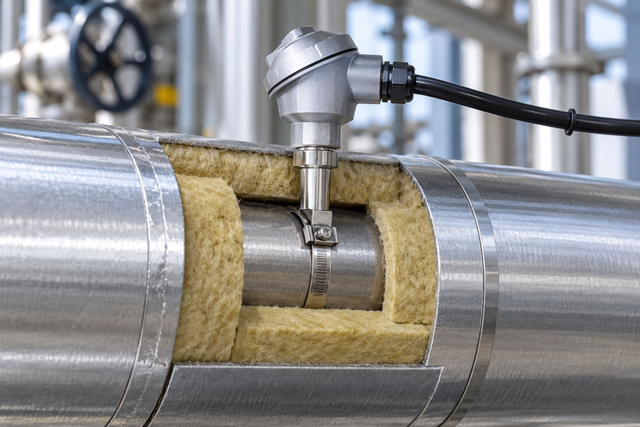
In many existing plants, an additional temperature measuring point needs to be installed even though the pipework has already been fully installed, is in operation and is completely insulated. Opening the pipe, welding in a new process connection or installing a thermowell is often only possible with considerable effort. An externally mounted temperature measurement using a surface, contact or clamp-on sensor therefore initially appears to be a simple solution.
In practice, however, the quality of such a retrofit measurement is not determined solely by the accuracy of the Pt100, Pt1000 or thermocouple used. Equally important factors include the thermal coupling between the pipe wall and the sensor, the condition of the surface, the contact pressure, the pipe material, the wall thickness, the insulation around the measuring point and possible thermal bridges via brackets, cables or metallic components.
Even a high-quality sensor with a flawless calibration can therefore indicate a value that differs considerably from the actual process condition if the installation situation is unfavorable. Conversely, a carefully planned surface measurement can provide very useful and reproducible results in many applications without opening the pressurized pipe.
The key principle is: When retrofitting temperature measurement on an insulated pipe, the complete thermal measuring point must be considered. It is not only the sensor itself that matters, but the entire heat transfer path from the medium through the pipe wall and contact point to the sensing element – as well as the unwanted heat transfer path from the sensor to the surroundings.
Table of Contents
- 1. What does an externally mounted temperature sensor actually measure?
- 2. Why insulation is crucial for measurement error
- 3. The heat transfer path from the medium to the sensor
- 4. Correctly designing the contact point between pipe and sensor
- 5. Avoiding thermal bridges at the measuring point
- 6. Selecting the correct position on the pipe
- 7. Which sensor design is suitable for retrofitting?
- 8. The electrical signal path is also part of the measuring chain
- 9. Identifying and diagnosing typical measurement errors
- 10. Practical procedure for retrofitting
- 11. Selection criteria for suitable temperature measurement technology
- 12. Suitable temperature measurement technology from ICS Schneider
- 13. Conclusion
- 14. Frequently asked questions about retrofitting temperature sensors
1. What does an externally mounted temperature sensor actually measure?
The most important question should be answered before selecting the sensor: Is the objective to measure the temperature of the medium inside the pipe as accurately as possible, or is the pipe wall temperature – or process information derived from it – sufficient?
An externally mounted temperature sensor has no direct contact with the medium. Its sensing element is thermally coupled to the outside wall of the pipe. The sensor therefore initially measures the temperature of the pipe wall at the contact point. There may be differences between the temperature of the flowing medium and the pipe wall temperature.
The magnitude of this difference depends on the application. A thin-walled metallic pipe with good heat transfer, sufficient flow and a carefully insulated measuring point behaves differently from a thick-walled pipe with low flow or a plastic pipe. Deposits on the inside of the pipe, changing flow rates or nearby heat tracing can also influence the result.
With a well-designed clamp-on measurement, the pipe wall temperature can follow the process temperature very closely. Nevertheless, during planning it should be clearly defined whether a non-invasive surface measurement is sufficient for the required measuring task or whether direct or invasive temperature measurement in the medium is necessary.
| Measurement principle | What is measured directly? | Advantage for retrofitting | Particular considerations |
|---|---|---|---|
| Surface / clamp-on sensor | Pipe wall temperature | The pipe generally does not need to be opened | Contact, insulation, pipe material and ambient influence |
| Immersion temperature sensor | Temperature in or close to the medium | More direct process measurement | Process connection, pressure tightness, insertion length and shutdown requirements |
| Sensor in thermowell | Temperature via thermowell and measuring insert | The sensor can often be replaced without opening the process | Insertion depth, heat dissipation, response time and thermowell design |
Surface measurement is therefore particularly attractive for existing plants when intervention in the pressurized pipe is to be avoided. However, it should not automatically be regarded as a fully equivalent replacement for every invasive process measurement. The permissible measurement deviation and required response characteristics must be suitable for the application.
2. Why insulation is crucial for measurement error
Thermal insulation is intended to reduce heat transfer between the pipe and its surroundings. This effect is also important for an externally mounted temperature measuring point.
If a section of insulation is simply removed for retrofitting, the sensor is installed and the measuring point is then left exposed, a completely different local thermal situation is created compared with the rest of the pipe. With a hot medium, additional heat is dissipated to the surroundings at this point. The pipe wall and therefore also the sensor may become cooler than the undisturbed pipe. With a cold pipe, the effect is reversed: additional heat flows from the warmer surroundings to the measuring point, which can result in a temperature reading that is too high.
The insulation therefore does more than simply reduce energy losses from the plant. In surface temperature measurement, it is also an integral part of the measuring point.
After installation, the thermal insulation should therefore be closed again as far as technically possible and restored to a level comparable with the original insulation performance. The actual contact area between the sensor and the pipe wall must be thermally shielded from the surroundings. At the same time, the connecting cable, neck tube or connection head must be suitable for their respective permissible temperature ranges.
For cold pipes, there is another important aspect. If the existing insulation, including the vapor barrier or outer cladding, is opened, the insulation system must subsequently be restored correctly. Otherwise, moisture and condensation may penetrate. In addition to changing the heat transfer characteristics, this can lead to long-term damage to the insulation system or the pipe itself.
3. The heat transfer path from the medium to the sensor
When assessing a surface temperature measurement, it is useful to consider the measuring point not as a single sensor but as a chain of several thermal resistances.
Heat must first be transferred from the medium to the inner wall of the pipe. It is then conducted through the pipe wall and transferred via the contact surface to the sensor. Within the sensor design, the heat must finally reach the actual sensing element.
At the same time, there is a second heat transfer path between the sensor and the surroundings. Heat can be dissipated or introduced via the housing, contact block, mounting strap, connecting cable, neck tube or other metallic components.
In simplified form, a heat flow can be described using the following relationship:
Q̇ = ΔT / Rth
Here, Q̇ represents the heat flow, ΔT the temperature difference and Rth the thermal resistance of the heat transfer path under consideration.
For good surface temperature measurement, the thermal resistance between the pipe and the sensing element should be as low as possible. At the same time, unwanted heat exchange between the sensing element and the surroundings should be minimized.
This leads directly to the two most important design measures: good contact with the pipe wall and good thermal insulation from the surroundings.
4. Correctly designing the contact point between pipe and sensor
Poor mechanical and thermal coupling is a major source of measurement error. Even a small air gap between the sensor and the pipe can significantly reduce heat transfer because air conducts heat much less effectively than metal.
The sensor should therefore be installed using a contact geometry designed for the respective pipe diameter. With professional clamp-on solutions, for example, the sensing element is pressed against the pipe wall by means of a spring or a defined mounting system. This keeps the contact more reproducible even in the presence of vibration or thermal expansion than with a loosely attached standard sensor.
Before installation, the contact surface should be inspected. Loose contamination, rust particles or deposits can impair heat transfer. Existing corrosion protection coatings, however, must not simply be ground away or removed unless this has been approved for the installation. Surface preparation must always be coordinated with the requirements for both the pipe and the sensor.
Whether additional thermal paste, thermal conductive foil or another coupling material is required depends on the sensor design used. A blanket statement such as “thermal paste should always be used with every surface sensor” would be technically incorrect. Some measuring systems are specifically designed for use with a particular heat transfer material, whereas in other designs the geometry of the contact surface itself already provides sufficient heat transfer.
The manufacturer’s installation instructions are therefore decisive.
Do not confuse the contact surface with the sensor surface
In a simple improvised solution, a cylindrical cable sensor is sometimes fastened to a pipe using a cable tie or hose clamp. Mechanically, this may initially work. Thermally, however, only two small surfaces may actually be in contact. At the same time, a significant part of the sensor remains exposed to the surrounding air.
A surface sensor designed specifically for pipe mounting, by contrast, has an adapted contact surface or corresponding coupling element. This provides more controlled heat transfer and improves the reproducibility of the measurement.
5. Avoiding thermal bridges at the measuring point
The term thermal bridge is often associated with building technology, but it also describes a relevant effect in insulated pipework: a structural component creates a highly conductive thermal path through the insulation and thereby changes the local heat flow.
Such a thermal bridge can be created, for example, by a massive metallic sensor bracket, a long uninsulated connection piece or a large opening in the metal cladding.
With a hot pipe, heat is transferred outward through these components. The local pipe wall temperature may therefore decrease. With a cold pipe, the same thermal path can transfer energy from the surroundings toward the pipe.
It is therefore not sufficient merely to ensure that the sensor is located underneath the insulation. Its structural connection to the outside environment must also be taken into account.
Very massive mounting elements can be particularly critical. If, for example, a large steel bracket is welded directly to the pipe wall for a small Pt100 sensor and then extends through the entire insulation layer, the bracket itself may create a substantially stronger heat transfer path than the actual sensor.
A good design therefore combines sufficient mechanical stability with the lowest possible unwanted heat conduction.
6. Selecting the correct position on the pipe
Even the best insulation cannot completely compensate for a poorly selected measuring position. A temperature measuring point should be installed where the pipe wall is as representative as possible of the process condition to be monitored.
Directly next to massive flanges, pump housings, valves or pipe supports, the thermal conditions may differ from those in a free section of pipe. Such components have a high thermal mass and often also provide good heat transfer to the surroundings.
Heat tracing must also be taken into account. If an electrical heating cable or steam trace is located immediately next to the temperature sensor, the sensor may respond more strongly to the heater than to the actual medium temperature. The position of the sensor relative to the heat tracing must therefore be selected deliberately.
Other influencing factors include low flow velocity, temporarily stagnant medium, temperature stratification or partially filled pipes. In such applications, the temperature may vary around the circumference of the pipe.
Before installation, it should therefore be verified whether the selected position truly represents the process condition that is to be monitored.
7. Which sensor design is suitable for retrofitting?
Different sensor designs can be used for retrofitted temperature measurement. Selection should not be based solely on the required temperature range, but also on accuracy, response behavior, accessibility and mechanical conditions.
Pt100 and Pt1000 surface sensors
Resistance thermometers are very well suited to many industrial temperature measurement applications. Pt100 sensors in particular are widely used due to their defined characteristic curve, good reproducibility and broad industrial acceptance.
For installation on a pipe, a surface or clamp-on version specifically designed for this purpose should be used wherever possible. The decisive factor is that the sensor design provides reproducible contact with the pipe wall.
Thermocouples
Thermocouples can be particularly suitable at higher temperatures or in applications requiring a robust and compact design. Special surface measurement versions with contact blocks or mounting straps are also available.
When using thermocouples, the correct thermocouple type, extension or compensating cable and the cold junction compensation of the evaluation electronics must also be considered.
Clamp-on systems
Specially developed clamp-on temperature sensors go beyond simply fastening a standard sensor to a pipe. The contact surface, contact pressure mechanism and thermal decoupling are specifically designed for pipe temperature measurement.
One example is the SITRANS TS300, which is also available in a clamp-on version for non-invasive temperature measurement on pipes. Such solutions are particularly attractive when the process must not be opened or the pipe must not be modified by adding an additional process connection.
8. The electrical signal path is also part of the measuring chain
Once the thermal measuring point has been correctly designed, the electrical transmission path must also be considered.
With a Pt100, a long connecting cable can add additional resistance, particularly in a 2-wire circuit. The evaluation unit may interpret this additional resistance as an increased sensor temperature. A 3-wire or 4-wire circuit can significantly reduce or, depending on the measuring system, largely eliminate this influence.
For longer distances between the measuring point and the control system, a temperature transmitter installed close to the sensor may be useful. The sensor signal can then be converted, for example, into a robust 4…20 mA signal. Depending on the transmitter, additional digital communication and diagnostic functions may also be available.
However, one point is particularly important: A transmitter cannot correct a thermal installation error. If the sensor is already measuring the wrong temperature because of poor contact or an open insulation section, even a highly accurate 4…20 mA transmitter will merely transmit that incorrect value reliably.
Further information can be found in our category Temperature Transmitters and Accessories for Temperature Sensors.
9. Identifying and diagnosing typical measurement errors
After retrofitting, a measured value should not automatically be regarded as correct simply because it appears plausible. Thermal installation errors in particular can produce stable values that seem entirely credible at first glance.
| Observation | Possible cause | Check |
|---|---|---|
| Hot pipe consistently indicates a temperature that is too low | Heat loss through open insulation, poor contact point or thermal bridge | Check insulation and contact, perform a comparison measurement |
| Cold pipe indicates a temperature that is too high | Heat input from the surroundings | Check insulation of the measuring point and connection design |
| Measured value responds very slowly | High thermal mass, poor contact or unsuitable sensor design | Observe response to a process temperature step change |
| Measured value changes with ambient temperature | Excessive ambient influence | Improve insulation and compare temperature behavior over the course of the day |
| Measured value changes suddenly after maintenance work | Contact has changed or insulation has been reassembled differently | Check mechanical installation and contact pressure |
| Constant deviation despite correctly calibrated sensor | Thermal installation error or wiring error | Check the sensor outside the plant and inspect the complete measuring chain |
| Measured value follows the heat tracing more strongly than the process | Sensor located too close to heating cable or steam trace | Check the position of the sensor relative to the heat tracing |
Sensor calibration and verification of the measuring point are two different things
This distinction is particularly important when troubleshooting. A removed Pt100 may be within tolerance in a calibration bath and still indicate an incorrect process value again after being reinstalled.
The calibration confirms the metrological characteristics of the sensor under the calibration conditions. It does not automatically prove that the complete temperature measuring point has been correctly installed in the plant.
In the event of unexplained deviations, the entire chain should therefore be considered: process, pipe wall, contact point, sensor, insulation, wiring, transmitter and evaluation system.
10. Practical procedure for retrofitting
A successful retrofit begins with an assessment of the existing installation. The pipe material, outside diameter, wall thickness, medium, normal temperature range, pressure, existing insulation and ambient conditions must first be known. It must also be clarified whether heat tracing is installed and how the pipe is operated.
The next step is to define which measured variable is actually required. For trend monitoring, energy monitoring or additional process information, a non-invasive measurement can often be highly useful. For highly accurate control or custody-transfer measurements, however, it must be verified whether the achievable overall measurement uncertainty of the surface measurement is sufficient.
A suitable measuring point is then selected. Strong local heat sources and heat sinks should be avoided wherever possible. The existing insulation should only be opened as far as necessary for correct installation.
The pipe wall or intended contact surface is then inspected and the sensor is installed in accordance with the manufacturer’s instructions. The specified tightening torque and any required thermal conductive foil or other coupling elements should be used as instructed.
After the sensor has been installed, the insulation is restored. Care should be taken to avoid leaving a large uninsulated area immediately around the sensor. Cable entries and connections must be designed so that the thermal and, where applicable, moisture-control function of the insulation system is maintained.
Finally, the measuring point should be verified during operation. Its behavior during a defined process temperature change is particularly informative. This makes it possible to determine whether the sensor responds plausibly and whether unusually long delays occur.
11. Selection criteria for suitable temperature measurement technology
| Criterion | Why it is important |
|---|---|
| Pipe material | Influences thermal conductivity and suitability of different mounting methods |
| Pipe diameter | Determines the geometry of the contact element and clamping device |
| Wall thickness | Influences heat transfer and the dynamic response between the medium and the outer wall |
| Medium and flow | Influence internal heat transfer and how representative the pipe wall temperature is |
| Process temperature | Determines suitable sensor, cable, insulation and mounting materials |
| Ambient temperature | Determines potential heat loss or heat input |
| Insulation | Crucial for the influence of the surroundings on the measuring point |
| Heat tracing | Can significantly influence the local measured value |
| Required accuracy | Determines whether a surface measurement is sufficient |
| Required response time | Determines sensor design and permissible thermal mass |
| Signal transmission | Direct Pt100, 3-/4-wire, 4…20 mA, HART or other interfaces |
| Hazardous area | Sensor, transmitter and installation must be approved for the respective application |
| Accessibility | Important for subsequent maintenance, replacement and calibration |
Particularly when retrofitting, it is worthwhile compiling this information before selecting a product. A temperature sensor chosen solely on the basis of its temperature range may be unsuitable for the specific pipe application.
12. Suitable temperature measurement technology from ICS Schneider
ICS Schneider Messtechnik offers a wide range of solutions for industrial temperature measurement – from resistance thermometers and thermocouples to surface and clamp-on measurements, transmitters, thermowells and calibration equipment.
An overview can be found under Temperature Measurement Technology and specifically under Temperature Sensors and Probes.
Various Resistance Thermometers and Pt100 Sensors are available for Pt100-based applications.
For applications in which the pipe must not be opened, the clamp-on version of the Siemens SITRANS TS300, for example, may be suitable. The appropriate version depends, among other factors, on the pipe diameter, temperature range, ambient conditions and required output signal.
For longer signal paths or integration into a process control system, Temperature Transmitters can also be used.
If an invasive measuring point with a thermowell is used instead of a surface measurement, insertion depth, flow influence and heat dissipation must also be taken into account. These aspects are covered in detail in our technical article “Temperature Sensors in Pipes: Identifying Heat Dissipation and Insufficient Insertion Depth as Measurement Errors”.
13. Conclusion
Retrofitting a temperature sensor on an already insulated pipe is generally possible. Non-invasive surface and clamp-on solutions in particular make it possible to add temperature measuring points without introducing a new process connection into the pressurized pipe.
However, the quality of the measurement depends critically on the thermal installation. A precise sensor alone does not guarantee a precise process value.
The contact point with the pipe wall must provide the best possible and reproducible heat transfer. At the same time, the sensor should be thermally shielded from the surroundings as effectively as possible. Open sections of insulation, massive metallic brackets or poorly arranged connection components can create thermal bridges and influence the measured value.
It is equally important to define what is actually to be measured. A surface sensor initially measures the pipe wall temperature rather than directly measuring the temperature of the medium. Whether the pipe wall temperature provides sufficiently accurate process information for the application must be assessed on a case-by-case basis.
When the pipe, insulation, contact point, sensor design and signal path are considered together during retrofitting, significantly more reliable and reproducible measured values can be achieved than by selecting the sensor based on sensor accuracy alone.
14. Frequently asked questions about retrofitting temperature sensors
Can a temperature sensor simply be mounted on the outside of an insulated pipe?
Not on the outside surface of the insulation if the objective is to measure the pipe temperature. For contact measurement, the sensor must be thermally coupled to the actual pipe wall. The insulation is opened locally for this purpose and should be professionally restored after installation.
Does a surface sensor measure the actual medium temperature?
It directly measures the temperature of the pipe wall at the contact point. How closely this corresponds to the medium temperature depends, among other factors, on the pipe material, wall thickness, medium, flow, temperature difference to the surroundings, contact quality and insulation.
Why must the measuring point be reinsulated after installation?
Without sufficient insulation, the pipe and sensor exchange more heat with the surroundings at the opened location. With a hot pipe, this can result in a measured value that is too low, while with a cold pipe it can lead to a value that is too high.
What is meant by a thermal bridge in this application?
A thermal bridge is a structural path through which heat can be transferred comparatively easily between the pipe and the surroundings. This can occur, for example, via a massive metal bracket, a connection piece or an uninsulated section. As a result, the local temperature at the measuring point changes.
Should thermal paste always be used between the temperature sensor and the pipe?
No. This depends on the sensor design and the manufacturer’s instructions. Some systems use thermal conductive material or special coupling foils, while others are designed so that no additional material is required. The manufacturer’s installation instructions should always be followed.
Is a Pt100 better than a thermocouple for this type of retrofit?
There is no general answer. Pt100 sensors are frequently used when good accuracy and reproducibility within the industrial temperature range are important. Thermocouples offer advantages at certain high temperatures and in robust applications. The decisive factors are the temperature range, required accuracy, response time, ambient conditions and sensor design.
Can a 4…20 mA transmitter correct the error caused by a poor contact point?
No. A transmitter improves or standardizes electrical signal transmission. However, it cannot correct an incorrect temperature value that has already been caused by poor thermal contact, unsuitable installation or insufficient insulation of the measuring point.
What must be considered with heat-traced pipes?
The position of the temperature sensor relative to the heat tracing is particularly important. If the sensor is installed immediately next to an electrical heating cable or steam trace, it may be influenced more strongly by the local heating system than by the actual medium temperature. The measuring point must therefore be positioned according to the intended measurement task.
How can you determine whether the retrofitted measuring point is working correctly?
In addition to a plausibility check, the sensor should be observed during process changes. Does the sensor respond plausibly to a temperature change? Is there an unusually long delay? Does the deviation change with ambient temperature? A suitable reference measurement can also help distinguish between installation errors and signal-related errors.
Which is better: a clamp-on sensor or a temperature sensor in a thermowell?
The two solutions meet different requirements. A clamp-on sensor can often be retrofitted without intervention in the pressurized pipe. A sufficiently deeply inserted sensor or a correctly designed thermowell, on the other hand, enables a more direct measurement of the process temperature. Which solution is more suitable depends on the required accuracy, process conditions, permissible installation effort and maintenance concept.
What information is required to select a suitable sensor?
At a minimum, useful information includes the pipe material, pipe diameter and wall thickness, medium, temperature range, ambient temperature, type and thickness of thermal insulation, existing heat tracing, required accuracy, desired response time, installation location, required output signal and, where applicable, requirements relating to explosion protection or hygienic design.