


Two tyre inflator gauges are to be tested in a workshop or inspection facility. Both instruments have the same measuring range and are regularly used at the same filling station or in the same workshop area. Does each instrument now have to be connected individually to the reference, brought to several test points, vented again and then the second instrument tested using the same procedure?
Not necessarily. A reference test unit such as the PRM-25 allows two tyre inflator gauges to be connected simultaneously to the same pneumatic test circuit. This means that both devices under test can be brought to the same pressure levels together with the reference pressure gauge.
This provides a major practical advantage: if, for example, a test point of 2.0 bar is set and sufficiently stabilized, the reference and both devices under test are basically exposed to the same test pressure within the common static pressure circuit. Their readings can therefore be compared directly.
However, simultaneous testing does not mean that all influencing factors automatically disappear. Two different tyre inflator gauges may have different internal volumes, hose lengths, valves, pressure-gauge mechanisms or venting functions. Even a small leak on only one device under test can change the common test pressure and therefore also affect the second device.
The readings must also be taken in an organized way. If the reference is recorded first, then device under test 1 is read and device under test 2 only significantly later while the pressure is slowly drifting, the three values were no longer recorded under exactly the same pressure condition.
The advantage of simultaneous testing therefore does not simply lie in connecting two instruments “somehow at the same time”. What matters is a stable common test circuit in which pressure changes have sufficiently settled and the reference and both devices under test are read as closely together in time as possible.
The most important rule is therefore: Two tyre inflator gauges can be tested very efficiently at the same time if both devices under test are connected to the same stabilized test circuit. However, each device remains an independent measuring instrument and must be evaluated and documented separately against the reference.
How does simultaneous testing of two tyre inflator gauges work?
In a conventional comparison test, one device under test is connected together with a more accurate reference to the same pneumatic pressure circuit.
The test pressure is generated and adjusted to a defined value. The pressure indicated by the reference is then compared with the value shown by the tyre inflator gauge.
For simultaneous testing, this principle is extended.
In addition to the reference, two tyre inflator gauges are connected to the same test circuit. In simplified form, the common pneumatic setup is therefore:
Pressure generation → common test circuit → reference + device under test 1 + device under test 2
After the pressure has been set and stabilized, all three measuring instruments are in the same static pressure system.
For example, a test point of 2.0 bar can therefore be assessed simultaneously on both tyre inflator gauges. The pressure is then increased to 3.0 bar and the reference is again compared with both device readings.
The number of pressure generation and adjustment operations can therefore be reduced compared with two completely separate tests.
Why both devices under test see the same static test pressure
In a closed or sufficiently stabilized pneumatic system, a common static pressure is established.
The reference, device under test 1 and device under test 2 therefore do not need to have exactly the same hose lengths or identical internal volumes in order to see the same static pressure after sufficient stabilization.
Different hose volumes mainly influence the transition from one test point to the next.
If the test pressure is increased, for example, from 1 to 3 bar, additional gas must fill all connected volumes. A larger test circuit therefore requires more gas and may need slightly more time after a pressure change until temperature and flow effects have subsided.
After complete stabilization, however, the same static pressure basically applies to all connected points within the same test circuit.
This is precisely the major advantage of a common comparison test: the two devices under test are not checked one after another under potentially slightly different conditions, but can be compared under the same pressure condition.
The reference remains the decisive value
Even when two tyre inflator gauges are connected simultaneously, this does not create an additional reference.
The decisive test pressure is still determined by the designated reference pressure gauge.
If the reference shows, for example:
2.000 bar
and the two devices under test show:
Device under test 1 = 2.05 bar
Device under test 2 = 1.98 bar
then each instrument is evaluated against the reference.
The difference between the two devices under test is additionally interesting, but it does not replace the reference measurement.
It would be incorrect, for example, to calculate an average from 2.05 bar and 1.98 bar and use this as the actual test pressure.
The reference provides traceability for the actual test pressure. The two tyre inflator gauges are the devices under test to be evaluated.
Direct comparison of the two devices under test
The parallel connection provides another very clear advantage: differences between two devices under test become immediately visible.
If both instruments are connected to the same test circuit and indicate, for example, 4.00 bar and 4.20 bar at a stable reference pressure of 4.00 bar, this difference cannot be explained by different actual test pressures.
Both instruments are exposed to the same pressure.
Provided that the test circuit is leak-tight and stable, the difference therefore results from the individual measuring behaviour of the two devices under test.
This can be particularly useful when a larger number of similar tyre inflator gauges are tested. Instruments showing significantly different behaviour become visible very quickly.
Nevertheless, every value still has to be documented individually.
Allow sufficient stabilization before reading
After each pressure change, a pneumatic test circuit requires a certain amount of time to reach a stable condition.
Gas heats up during compression and cools down during expansion. These temperature changes can briefly cause pressure changes even when no gas is escaping from the system.
With a larger test volume and two connected tyre inflator gauges, this effect may be more noticeable than with a very small setup.
For this reason, readings should not be taken immediately after reaching a new test point.
The pressure is first adjusted as accurately as possible using the fine regulator. Then the system is allowed to settle until the reference reading is sufficiently stable.
Only then should the reference and both devices under test be evaluated.
For reproducible testing, it is advisable to use the same stabilization criterion at every test point.
Waiting five seconds at one point and reading immediately at the next unnecessarily reduces comparability.
Consider different hose and instrument volumes
Two tyre inflator gauges do not necessarily have the same internal design.
One instrument may have a short connection hose while another has a considerably longer one. Valve blocks, pressure-gauge housings and internal pressure chambers can also differ.
As a result, the pneumatic volumes also differ.
For the final static pressure, this is normally uncritical after sufficient stabilization.
However, it is relevant for pressure adjustment.
When a second device under test is connected, the total volume of the test circuit increases. More gas must be introduced for the same pressure increase than when only one device under test is connected.
With manual pressure generation, the test setup may therefore feel somewhat different.
The fine regulator or volume adjuster remains important for setting the required test point precisely after the rough pressure has been generated.
Different volumes are therefore no reason to avoid simultaneous testing. They simply have to be considered during pressure generation and stabilization.
Why a leak in one device can affect both measurements
The common test circuit also has one important consequence:
A leak in a single connected component affects the entire test circuit.
If, for example, the hose of device under test 2 is leaking, it is not only device under test 2 that loses pressure.
Because the reference, device under test 1 and device under test 2 are pneumatically connected, the pressure drops throughout the entire system.
The reference then also shows a decreasing value, and device under test 1 is likewise exposed to the changed pressure.
This can lead to incorrect interpretation if only the displays of the two devices under test are observed.
Before the actual measurement series, the tightness of the entire test setup should therefore be assessed.
A slowly drifting test point is not automatically an indication of an inaccurate reference gauge or an unstable device under test. The cause may be a small leak at a coupling, hose or one of the tyre inflator gauges.
Do not operate valves or venting functions during measurement
Tyre inflator gauges typically have functions for filling and releasing pressure.
If such a function is operated during the common test, the pressure throughout the entire test circuit changes.
This also applies if a valve is operated on only one of the two devices under test.
During the actual reading, both devices under test should therefore remain in a steady and unchanged condition.
If a particular valve function of a tyre inflator gauge is to be tested, this should be treated as a separate test step rather than being performed simultaneously with the static comparison measurement.
After every actuation, the required test point must be reset and stabilized again.
Read the reference and both devices as simultaneously as possible
Even a good pneumatic test setup is not absolutely unchanging.
Small temperature changes, microscopic leaks or mechanical movements can cause the pressure to change slowly.
The reference and both devices under test should therefore be read within as short a time window as possible.
With an analogue tyre inflator gauge, the pointer should be read without parallax error wherever possible. With digital devices, it must be taken into account that their displays may have different update rates.
A sensible procedure is, for example, to first observe stability on the reference and then document the reference, device under test 1 and device under test 2 immediately one after another.
For particularly slow or fluctuating displays, a second reading cycle may be useful.
This makes it possible to determine whether the test point remained stable during data acquisition.
Approach several test points together
A reliable test should not be limited to a single pressure point if the applicable test procedure requires several points.
A tyre inflator gauge may, for example, indicate almost exactly at 2 bar but deviate significantly at 4 or 6 bar.
With two connected devices under test, the specified test points can be run through together.
The test sequence could, for example, be:
0 bar → 1 bar → 2 bar → 3 bar → 4 bar → 5 bar
The actual test points naturally depend on measuring range, test procedure and required evaluation.
At each point, the pressure is first stabilized and then all three readings are documented.
This produces two complete measurement series even though the test pressure only had to be generated once for each pressure level.
Perform increasing and decreasing test sequences together
With mechanical and electromechanical pressure measuring instruments, it can make a difference whether a test point is approached from a lower or a higher pressure.
This effect is considered, among other things, as hysteresis.
The common test circuit is also very practical for this purpose.
Both devices under test can first be tested together in the increasing direction.
After reaching the highest specified pressure point, the pressure is then reduced step by step and the same points are approached again in the decreasing direction.
This gives both tyre inflator gauges exactly the same pressure history.
If device under test 1 shows, for example, 3.00 bar in the increasing direction and 3.10 bar in the decreasing direction at the 3 bar point, while device under test 2 shows 3.00 bar in both cases, the difference becomes immediately visible.
Parallel testing therefore improves not only speed but also the comparability of the mechanical loading history.
Assess zero point and return to zero separately
After completion of a pressure sequence, the test circuit is depressurized again.
It can then be checked whether both tyre inflator gauges return correctly to zero.
Here too, simultaneous testing offers an advantage: both devices under test were previously exposed to the same pressure levels.
If only one of the two pointers remains visibly above zero after complete depressurization, this indicates instrument-specific behaviour rather than a different previous test pressure.
However, it is important that the test circuit is actually fully vented.
A small residual pressure in the common system would influence both instruments and could incorrectly be interpreted as a zero-point deviation.
Calculate measurement deviation separately for each device
Even with a common measurement series, each device under test has its own set of measured values.
The deviation at each test point can be determined in simplified form as:
Deviation of device under test = indication of device under test − reference value
Example at a reference pressure of 3.000 bar:
Device under test 1 = 3.05 bar → deviation +0.05 bar
Device under test 2 = 2.96 bar → deviation −0.04 bar
The two instruments therefore differ from each other by a total of 0.09 bar.
However, this difference between the devices under test is not used for assessment against a permissible tolerance.
The decisive factor is the individual deviation of each instrument from the reference.
Device under test 1 may therefore be within the permissible tolerance while device under test 2 exceeds it – or vice versa.
Simultaneous comparison testing is not a joint calibration
The common pneumatic setup can easily create the impression that both instruments are effectively being calibrated as one combined device under test.
This is not the case.
Each tyre inflator gauge has its own identification, display characteristics, measurement error and history.
If formal calibration results are documented, the results must therefore be clearly assigned to the respective instrument.
The common pressure signal merely reduces the effort required to generate the test points and improves direct comparability.
It does not replace individual result evaluation.
A calibration certificate or test report must therefore identify the respective instrument and its individual measurement results accordingly.
Measurement uncertainty is not automatically halved
Connecting two devices under test at the same time does not make the reference more accurate.
The measurement uncertainty of the comparison test continues to be determined by factors including the reference, calibration uncertainty, resolution, stability, reading and test setup.
The fact that two devices under test indicate the same value is not proof that this value is correct.
If, for example, both devices indicate 3.10 bar while the reference indicates 3.00 bar, the two instruments agree very well with each other but both have a similar deviation from the reference.
Conversely, two devices under test can show different readings even though the reference is completely stable.
Simultaneous testing therefore primarily improves the comparability of the test conditions – not automatically the metrological accuracy of the reference.
Practical example: testing two tyre inflator gauges simultaneously
A workshop organization has several analogue tyre inflator gauges with a typical operating range up to 6 bar.
Two instruments are connected simultaneously to the PRM-25.
After the leak-tightness check, a test pressure of 1.0 bar is first set.
After stabilization, the following values are recorded:
| Reference | Device under test 1 | Device under test 2 |
|---|---|---|
| 1.000 bar | 1.00 bar | 1.05 bar |
| 2.000 bar | 2.02 bar | 2.08 bar |
| 3.000 bar | 3.03 bar | 3.12 bar |
| 4.000 bar | 4.04 bar | 4.17 bar |
Even during the test, it becomes apparent that device under test 2 increasingly indicates too high a value as the pressure rises.
Because both devices were connected at the same time to the same stabilized test circuit, this difference cannot be explained by different test-pressure conditions.
The actual decision as to whether the respective deviations are permissible is then made on the basis of the tolerance or specification applicable to the test task.
If a decreasing measurement sequence is then carried out, it can additionally be checked whether one of the two instruments shows noticeable hysteresis.
The example clearly illustrates the practical advantage: one pressure sequence produces two complete and directly comparable test series.
Recommended test procedure with two devices under test
Before testing begins, both tyre inflator gauges are clearly identified and connected to the designated test connections.
The complete setup is then checked for obvious leaks. Particular attention should be paid to quick couplings, hoses and the connections of both devices under test.
The first test point is then approached. The test pressure is generated using the intended pressure source and adjusted as accurately as possible using the fine regulator.
After sufficient stabilization, the reference and both devices under test are read and documented within a short time interval.
This procedure is repeated for all specified test points.
If hysteresis evaluation is required, the same sequence is then performed in the decreasing pressure direction after the highest test point has been reached.
Finally, the test circuit is completely depressurized and the return of both instruments to zero is checked.
This produces two complete test data sets with a common reference-pressure history.
Typical errors during simultaneous testing
| Observation | Possible cause | Sensible check |
|---|---|---|
| Reference pressure slowly decreases | Leak at a device under test, hose or connection | Check the complete test circuit for leaks |
| Pressure drops significantly after connecting the second device | Additional internal volume is being filled | Reset and stabilize the test pressure |
| Devices under test 1 and 2 indicate different values | Individual instrument deviations | Evaluate both values separately against the reference |
| All readings change after operating one device under test | Common pneumatic test circuit | Reset and stabilize the test point |
| Values differ between increasing and decreasing tests | Hysteresis of the respective device under test | Document both pressure directions separately |
| Both instruments show residual pressure after venting | Test circuit may not yet be completely depressurized | Vent completely and check the reference |
Most problems can be avoided if pressure generation, stabilization, reading and venting are performed according to a consistent procedure at every test point.
When simultaneous testing is particularly economical
The practical time advantage increases with the number of instruments that need to be tested repeatedly.
For a single occasional test, it may make little difference whether one or two devices under test are connected at the same time.
In inspection facilities, larger workshop organizations, filling-station chains or service companies, however, numerous tyre inflator gauges may have to be tested regularly.
With a parallel setup, each test point only has to be generated and stabilized once.
The actual documentation must still be carried out separately for each instrument, but the pneumatic test procedure can be performed more efficiently.
In addition, direct comparability is particularly good because both devices under test are exposed to the same pressure levels at the same time.
The economic advantage therefore does not result from reduced metrological care, but from more efficient use of a test point that has already been stably adjusted.
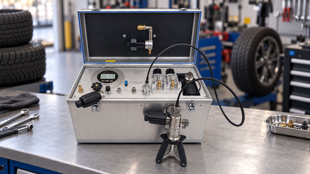
PRM-25 as a test setup for two tyre inflator gauges
The PRM-25 was developed specifically for testing and calibrating tyre inflator gauges in workshops, filling stations and inspection facilities.
The test unit has two Airfix device connections with clamping brackets. This allows two tyre inflator gauges to be connected simultaneously to the common test circuit.
In the current version, a precision digital pressure gauge of type ADT681 is integrated as the reference. Reference measuring ranges of 6, 10, 16, 25 or 40 bar are available for different test tasks.
The reference measuring range should be selected according to the actual test points and the required test tolerance. An unnecessarily large measuring range is not automatically advantageous.
For pressure generation, the PRM-25 has an integrated ICP 40.2 precision calibration hand pump. This means that testing can also be performed independently of an external compressed air supply.
A 2-litre compressed air reservoir is also integrated and can be used as a buffer or pressure reservoir.
An external compressed air supply can also be connected. This is particularly practical when a larger number of tests have to be carried out regularly.
The required test point can be approached precisely using the fine regulator or volume adjuster.
This fine adjustment is especially useful when two devices under test are connected because the total volume of the pneumatic system is larger than when testing only one device.
PRM-25 reference test unit for tyre inflator gauges at ICS Schneider
Calibration cases and test cases at ICS Schneider
Further reading: Selecting the correct reference for tyre inflator gauges
Further reading: Testing tyre inflator gauges with increasing and decreasing pressure
Further reading: Testing tyre inflator gauges without an external compressed air supply
Conclusion
The ability to test two tyre inflator gauges simultaneously is more than just a practical additional feature of a test case.
After sufficient stabilization, both devices under test can be evaluated under the same static reference pressure. This makes it possible to compare the readings directly and run through multiple pressure points particularly efficiently.
However, the common test circuit also has consequences. A leak on only one tyre inflator gauge affects the pressure seen by both devices. Likewise, operating a filling or release valve on one instrument changes the entire pneumatic condition.
Different hose and instrument volumes are fundamentally not a problem for the final static test pressure, but they can influence pressure generation and the required stabilization time.
The reference and both devices under test should therefore only be read once a stable pressure condition has been reached and preferably within a short time window.
Despite the common test setup, the two devices under test remain independent measuring instruments. Measurement deviation, hysteresis, zero-point behaviour and permissible tolerance must be assessed separately for each instrument.
A common test is therefore not equivalent to a common calibration. Rather, it enables two individual comparison tests under particularly comparable pressure conditions.
Especially for inspection facilities and organizations with a larger number of tyre inflator gauges that require regular testing, this setup can significantly reduce the time required without compromising proper reference evaluation.
FAQ on simultaneously testing two tyre inflator gauges
Can the PRM-25 test two tyre inflator gauges at the same time?
Yes. The PRM-25 has two device connections, allowing two tyre inflator gauges to be connected simultaneously to the same test circuit.
Do both devices under test really see the same pressure?
After sufficient stabilization, both devices under test are connected to the same static pneumatic test circuit and therefore basically see the same test pressure.
Do different hose lengths therefore not matter?
For the stable final static pressure, they are normally not particularly relevant. Different volumes can, however, influence how quickly a new test point is reached and stabilized.
What happens if one of the devices under test is leaking?
Because both devices and the reference are connected to the same test circuit, a leak on one device can cause the pressure to drop throughout the entire system.
Can I operate the release valve on one device during the measurement?
No, not without changing the common test point. Any venting through one connected device affects the entire test circuit.
Why should the readings be taken as closely together in time as possible?
If the test pressure is slowly drifting, readings taken far apart in time would represent different actual pressure conditions.
Can I compare the two devices under test directly with each other?
Yes. Because they are exposed to the same stabilized pressure at the same time, the direct difference between their indications is very informative. However, the actual assessment is carried out individually against the reference.
Can I average the two device readings to determine the actual pressure?
No. The decisive test pressure is determined by the reference. The devices under test are evaluated against this reference value.
Is the measurement more accurate if two devices under test are connected simultaneously?
Not automatically. Simultaneous testing primarily improves the comparability of the pressure conditions. Accuracy and measurement uncertainty are still determined by the reference and the test procedure.
Can two instruments be tested simultaneously with increasing and decreasing pressure?
Yes. Both devices under test can follow the same increasing and then decreasing pressure sequence. This also allows their hysteresis behaviour to be compared very effectively.
Does the zero point need to be checked separately for both instruments?
Yes. After complete depressurization, the return to zero of each device under test is assessed separately.
Is simultaneous testing the same as a common calibration?
No. Although both instruments are exposed to the same test pressure, each has its own measurement results and must be documented and evaluated individually.
Can one common test report be used for both instruments?
An organizationally combined document is possible, provided that the measured values and identification of each device under test are clearly separated and traceably documented. The exact form depends on the relevant quality or test procedure.
Why should leak-tightness be checked before testing?
A small leak can change the common test pressure and therefore impair the comparability of all connected measuring instruments.
Can the PRM-25 be used without an external compressed air supply?
Yes. The integrated precision calibration hand pump can generate the required test pressure.
What is the function of the internal 2-litre reservoir?
It can be used as a buffer or compressed air reservoir and supports a stable pneumatic test setup.
Which reference is used in the current PRM-25?
The current product description specifies the ADT681 precision digital pressure gauge as the integrated reference.
Which reference measuring ranges are available?
The current product description specifies 6, 10, 16, 25 and 40 bar.
Why should the reference range match the test task?
Depending on the accuracy specification, an unnecessarily large measuring range can result in less favourable absolute measurement uncertainty in the typical tyre-pressure range. The reference range should therefore safely cover the required test points while remaining sensibly dimensioned.
When is simultaneous testing particularly worthwhile?
It is particularly useful for inspection facilities, workshop groups, filling stations, tyre service companies and other organizations that regularly need to test multiple tyre inflator gauges.
What information should be documented for each device under test?
At minimum, the instrument identification, test points, reference values, respective device readings, resulting deviations and the applied evaluation or tolerance criterion should be documented in a traceable manner.