


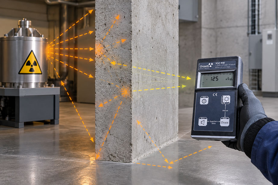
A radiation source is located behind massive shielding. A significantly elevated dose rate was measured in front of the shielding, while behind the wall the dose rate meter shows only a small fraction of this value. At first glance, the shielding effect therefore appears to be clearly determined.
In practice, however, the situation is often more complex. A measuring instrument behind shielding does not detect only the photons that have passed directly through the shielding. Radiation can be scattered within the shielding material, bypass the shielding at an edge, pass through cable or pipe penetrations, or be scattered towards the measuring point by floors, walls and adjacent machine components.
The measured value is therefore the result of the entire spatial radiation situation at the detector.
Moving the instrument by only a few centimetres can already change the value if the detector is located near a shielding edge, a penetration or a strongly directional radiation field. The orientation of the instrument can also play a role because real detectors do not have completely direction-independent sensitivity.
In addition, the shielding itself can alter the energy spectrum. Lower photon energies are often attenuated more strongly than higher energies. At the same time, scattering processes produce photons with changed, usually lower, energies. Behind the shielding, the measuring instrument may therefore be exposed to a different radiation spectrum than in front of it.
The most important rule is therefore: A dose-rate measurement behind shielding is always a measurement at a defined position within a specific geometry. Distance, measuring height, detector orientation, shielding material, shielding edges, penetrations, surroundings and operating condition of the source must all be considered when measured values are compared or the effectiveness of shielding is evaluated.
What does the dose rate meter measure behind shielding?
A dose rate meter detects the radiation that reaches its detector at the respective location.
Behind real shielding, this measured value can consist of several contributions.
Some of the original photons can pass through the shielding without interaction. This component is often referred to as the primary or unscattered component.
Other photons interact within the shielding material and change their direction or energy. Some of these scattered photons can subsequently also reach the detector.
Additional radiation can bypass the actual shielding via edges, openings or other geometrical paths.
Finally, natural or operational background radiation is also present at the measuring location.
In simplified form, the displayed value can therefore be described as a superposition:
Measured value = transmitted primary radiation + scattered radiation + bypass/leakage radiation + background
These contributions cannot be separated directly with a conventional dose rate meter. The instrument initially displays only the total dose rate at the detector location.
For correct interpretation, it must therefore be understood which radiation paths are possible in the specific installation.
Why simple exponential attenuation does not describe everything
For an idealized narrow photon beam, attenuation in a homogeneous material can be described in simplified form using an exponential function:
I = I0 · e−µx
where:
I0 = incident intensity
I = uncollided component behind the shielding
µ = linear attenuation coefficient
x = material thickness
This relationship is very useful for many basic shielding considerations.
However, it essentially describes the fraction of photons that pass through the material thickness under consideration without relevant interaction.
In real broad shielding, photons do not necessarily disappear from the entire radiation field after an interaction. They can be scattered and subsequently reach the measuring point by a different path.
The actual dose-rate value behind the shielding can therefore be higher than the pure exponential calculation for the unscattered component would suggest.
This does not mean that the attenuation law is incorrect. It simply does not describe every contribution within a real radiation field.
How scattered radiation is produced behind shielding
Gamma and X-ray photons can undergo different interactions when passing through matter.
For many typical radiation-protection energies, Compton scattering plays an important role. In this process, a photon transfers part of its energy to an electron and is subsequently scattered in a different direction with lower energy.
A photon originally directed towards the shielding can therefore, after one or more interactions, travel towards a measuring point that is no longer geometrically located on the original beam axis.
The shielding therefore reduces radiation, but at the same time can itself become a source of scattered photons.
The size of this contribution depends, among other things, on photon energy, material, thickness and geometry.
The irradiated area also plays a role. If a large shielding surface is irradiated, there are more locations at which scattering processes can occur than with a very narrow collimated beam.
This is precisely why the same material thickness can produce different actual measured values behind the shielding under different irradiation geometries.
What does the buildup effect mean?
In shielding calculations, the additional contribution of scattered photons is often taken into account using a so-called buildup factor.
In simplified form, the actual radiation quantity behind shielding can then be described as:
I ≈ I0 · B · e−µx
The factor B is greater than or equal to one and takes into account that, in addition to the unscattered component, additional scattered photons reach the point under consideration.
The buildup factor is not a universal constant.
It depends, among other things, on photon energy, shielding material, material thickness and the geometry being considered.
For this reason, a single measured shielding factor should not automatically be interpreted as a universally applicable material property.
A steel wall can have a certain shielding effect for a specific gamma energy and geometry. At another photon energy or with a much larger irradiated area, the ratio between primary and scattered radiation may be different.
Why geometry changes shielding effectiveness
Shielding is not only a question of material.
The spatial arrangement of source, shielding and detector determines which radiation paths are possible at all.
With a small, approximately point-like source, a sufficiently large homogeneous shielding plate and a detector located far from all edges, the geometry is comparatively straightforward.
In a technical installation, conditions are rarely this ideal.
The radiation source may be extended. The shielding has edges, fastenings and penetrations. Other system components are located adjacent to the radiation path and can themselves scatter radiation.
The distance between source and shielding also influences the size of the irradiated area on the shielding.
If the shielding is positioned close to the source, only a comparatively small area may be irradiated. At a greater distance, a significantly larger area of the wall can contribute to the scattered field.
A measurement result should therefore always be documented together with the actual geometry.
Consider shielding edges and bypass radiation
A common cause of unexpectedly high measured values is not insufficient shielding thickness, but the edge of the shielding.
A detector positioned directly behind the centre of a sufficiently large shielding plate experiences a different situation from a detector located only a few centimetres from its edge.
Near an edge, photons can pass through the shielding along a considerably shorter material path or bypass it completely.
In addition, the shielding edge itself can scatter radiation towards the detector.
This can create a steep spatial gradient.
Moving the detector by, for example, 10 or 20 cm can then cause a much greater change in measured value than the same displacement far away from the shielding edge.
Especially when checking local shielding, measurements should therefore not be limited to the geometric centre.
Transitions, edges and connection areas must also be included in the assessment.
Recognize penetrations and gaps as radiation paths
Technical shielding often contains openings.
Cables, pipes, ventilation ducts, shafts or mechanical actuating elements must pass through the shielding.
Doors, plate joints and maintenance openings also create structural interruptions.
A direct line-of-sight channel through such an opening can provide a significantly shorter shielding path than the solid material alongside it.
This effect is often referred to as radiation streaming.
Even if a penetration is angled and there is no direct line of sight to the source, photons can travel through the channel via multiple scattering processes.
Shielding can therefore work extremely well over a large central area while a small penetration produces a locally much higher measured value.
For real shielding verification, such structural details are therefore often more important than a measurement at only one central point.
Scattering from floors, walls and machine surroundings
Not all scattered radiation reaching the detector must originate in the shielding itself.
Photons can, for example, strike the floor in front of the shielding and be scattered from there into the area behind the wall.
Similar effects can occur at ceilings, side walls, steel structures, vessels or machine components.
The real measurement environment can therefore create additional radiation paths that are not obvious in a simple two-dimensional diagram.
This can become particularly noticeable if shielding covers only part of the room cross-section.
The direct radiation is strongly reduced, while scattered radiation via the floor or side areas can still reach the measuring point.
As the quality of the direct shielding increases, the relative contribution of this scattered radiation can even become increasingly important.
Behind highly effective shielding, the measured value may therefore no longer be dominated by what passes directly through the wall, but by what bypasses it spatially or is scattered from other surfaces.
Define the measurement position precisely
The statement “3 µSv/h was measured behind the shielding” is only reproducible to a limited extent without further information.
For a reliable comparative measurement, it must be clear where the sensitive region of the detector was located.
Relevant parameters include the distance from the shielding surface, height above the floor and lateral position relative to the source, shielding edge and possible penetrations.
The distance from the actual radiation source also remains important.
If a comparative measurement is carried out in front of and behind shielding, it must not be overlooked that the distance to the source may also have changed at the same time.
Two effects then act simultaneously:
geometrical distance change + material shielding
Simply dividing the two measured values therefore does not necessarily provide the pure transmission factor of the shielding.
For reproducible measurements, it is advisable to define or mark the measuring point mechanically and unambiguously.
Keep detector orientation reproducible
Real dose rate meters do not respond completely independently of the direction of incident radiation.
The detector is located inside a housing. Electronics, battery, housing walls and other components can place different amounts of material between the radiation field and the sensitive detector volume depending on the direction of incidence.
The geometry of the actual detector can also result in angular dependence.
An elongated Geiger-Müller tube, for example, can respond differently when radiation enters along its axis than when it is irradiated from the side.
For comparative measurements behind shielding, the instrument should therefore always be oriented in the same way.
Changing from “display facing the source” to “rear of the instrument facing the source” could otherwise introduce an additional difference that is incorrectly attributed to the shielding.
For measurements using an external probe, the same principle applies: the orientation of the actual probe head is also part of the defined measurement geometry.
Consider energy dependence behind shielding
Shielding does not attenuate all photon energies equally.
The attenuation coefficient depends on photon energy and material.
As a result, shielding changes not only the number of photons but often also the spectral composition of the radiation field.
Scattering processes additionally produce photons with lower energies.
The dose rate meter behind the shielding may therefore be exposed to a different energy spectrum from that in front of the shielding.
For quantitative measurements, the instrument used must be suitable for this energy range.
Energy-compensated dose rate meters are designed to limit energy dependence within their specified range.
However, this compensation applies only within the stated instrument specifications.
Particularly with very soft X-rays or complex scattered spectra, it should therefore be checked whether the energy range of the instrument is suitable for the actual application.
Correctly account for background radiation at low measured values
The more effective the shielding, the smaller the remaining source contribution at the measuring point becomes.
At some point, this value approaches the natural or local background radiation.
Assume that 0.12 µSv/h is measured behind shielding while the local background dose rate without the active source is already 0.09 µSv/h.
In this case, only approximately 0.03 µSv/h of the difference originates from the operating condition under consideration, provided both measurements were performed under comparable conditions.
With such small differences, the requirements for measurement time, instrument stability and reproducibility increase significantly.
The background measurement should therefore preferably be performed at the same measuring point and with the same detector orientation.
Other operational radiation sources in the surrounding area must also be considered.
A background measurement from the previous day under a different operating condition is not necessarily representative of the current measurement.
Consider measurement time and statistical fluctuations
In many dose rate meters, ionizing radiation is detected through individual detection events.
These events occur statistically.
At high count rates, many events are available within a short time and the measured value can stabilize relatively quickly.
Behind effective shielding, however, the dose rate may be very low. The detector then records significantly fewer events within the same period.
The relative statistical uncertainty increases accordingly.
A value fluctuating, for example, between 0.08 and 0.16 µSv/h within a few seconds does not automatically mean that the radiation field is continuously doubling and halving.
Part of the fluctuation may be purely statistical.
For quantitative assessment, a sufficient measurement or averaging time should therefore be used.
The required duration depends on the dose rate, detector, instrument software and the desired statement.
For comparative measurements, identical stabilization criteria should be used wherever possible.
Do not oversimplify the half-value layer
The half-value layer is a commonly used quantity for describing the shielding effectiveness of a material.
In simplified terms, it is the material thickness that reduces a considered radiation component to one half.
Under idealized monoenergetic conditions, the following applies to the unscattered component:
I / I0 = 1 / 2
after one half-value layer.
After two half-value layers, the idealized result is:
1 / 4
and after three:
1 / 8
In a real broad radiation field, however, the measured total value may deviate from this simple sequence because scattered radiation and spectral changes are also present.
The half-value layer remains a very useful planning parameter, but it should not be confused with a universal guarantee that the actual measured value behind every real construction will decrease exactly by successive powers of two.
Determine shielding effectiveness by comparative measurement
A practical method for assessing shielding is to compare measurements under operating conditions that are as identical as possible with and without the shielding effect.
Particular attention must be paid to the geometry.
The source or system should operate in the same condition. The detector should have the same orientation and the measured values must refer to comparable distances.
An idealized transmission factor can then be described as:
T = dose rate behind shielding / reference dose rate
However, this quotient is only meaningful if both values actually represent comparable geometrical conditions.
If, for example, the reference measurement is carried out at a source distance of 1 m and the shielded measurement at 2 m, the quotient also includes the effect of distance.
With approximately point-source geometry, this influence may possibly be corrected mathematically. With extended or strongly scattering sources, a simple correction is more difficult.
For practical radiation-protection assessment, it is therefore often more useful to measure the actual relevant workplace or access area directly rather than calculating backwards from an idealized reference value.
Practical example: measurement behind a shielding wall
In an industrial test facility, a gamma source is located behind a local shielding wall.
Before optimization of the shielding, a dose rate of 85 µSv/h is measured at a defined point behind the wall.
An additional shielding plate is installed. A simple material calculation suggests that the direct unscattered radiation component should be reduced very significantly.
After modification, however, the measuring instrument still shows 18 µSv/h at the original measuring point.
The value is therefore considerably lower than before, but higher than would be expected from a consideration of the unscattered primary beam alone.
A measurement ten centimetres further towards the shielding edge gives 31 µSv/h.
Further measuring points show that the value is low along the central shielding area but rises significantly near the edge.
The additional shielding plate itself therefore works as intended. However, a relevant part of the remaining radiation field reaches the area through the geometry of the edge region or via scattered radiation.
The solution is therefore not simply to continue increasing the thickness of the central shielding.
Instead, the edge geometry is reviewed and the overlap of the shielding elements improved.
After the modification, the same measurement grid is recorded again.
This example shows why a single central measured value is not sufficient to assess a complete shielding structure.
The figures are provided only for illustration and do not represent general limit or release values.
Use a measurement grid instead of only one measuring point
For a larger shielding area, a systematic measurement grid can provide significantly more information than one individual measuring point.
Several defined positions along the shielding are measured.
Areas around plate joints, doors, penetrations and edges are particularly important, as are positions at typical occupancy or working heights.
The spacing between measuring points depends on the size and geometry of the installation.
If a nearly uniform low value is observed over large areas and only one position shows a clear peak, this indicates a local geometrical problem.
If the dose rate increases similarly over the entire area, the general shielding effectiveness or the operating state of the source is more likely to require investigation.
A documented measurement grid also provides a major advantage for later repeat measurements.
After modifications or maintenance work, measurements can be repeated at exactly the same points and the development compared directly.
Consider measuring range and overrange conditions
The expected dose rate in front of shielding may be many orders of magnitude higher than behind it.
An instrument that is optimally suited to the low values in the protected area is therefore not necessarily suitable for measurements on the source side of the same shielding.
Before approaching an unknown radiation area, the possible maximum value should be estimated.
If the actual dose rate exceeds the instrument’s measuring range, it can no longer provide a reliable quantitative result.
With certain detector technologies, it must additionally be considered how the instrument behaves at very high count rates and under possible saturation conditions.
The safe strategy is therefore not to keep moving closer to the source with a standard measuring instrument until a usable value appears.
For high dose rates, measuring systems with extended ranges or telescopic probes can be used.
This allows the detector to remain at the required measuring point while the person performing the measurement maintains a greater distance.
Plan measurements with the lowest practical exposure
A measurement is itself part of radiation protection and should therefore also be planned according to radiation-protection principles.
The measuring point must be meaningful from a metrological perspective, but unnecessary time in an elevated radiation field should also be avoided.
If an unknown dose rate is expected, approaching from a greater distance is preferable to starting directly next to the suspected source.
At high or difficult-to-access measuring points, an external or telescopic probe can provide the necessary separation between measuring head and operator.
The distance to the measuring head must not be confused with the measurement distance itself. For the measurement geometry, the position of the detector or probe is relevant, not the position of the display or operator.
Before starting, withdrawal or abort criteria should also be defined in accordance with the operational radiation-protection concept.
A quantitative shielding test should not be carried out by having a person repeatedly move closer to an unknown radiation field without appropriate preparation.
Suitable radiation measurement technology at ICS Schneider
Within its radiation measurement technology range, ICS Schneider Messtechnik offers various GRAETZ instruments for dose-rate measurement, personal dosimetry, contamination detection and special applications.
The GRAETZ GammaTwin is a compact dose rate meter for gamma and X-ray radiation. It measures the ambient dose equivalent rate Ḣ*(10) using an energy-compensated Geiger-Müller tube.
The dose-rate measuring range extends from 0.5 µSv/h to 70 mSv/h. This makes the instrument suitable, among other applications, for mobile control measurements in areas where the expected dose rate lies within this range.
For more extensive tasks, the GRAETZ X5C plus is available. The system also measures gamma and X-ray radiation and can be combined with various external measuring probes via its probe interface.
This expandability is particularly useful when the measuring task exceeds the range or geometry of the internal detector.
For high dose rates or difficult-to-access measuring locations, the GRAETZ Telescopic Probe DE can be used. The stainless-steel telescope can be continuously extended to an overall length of up to 4 m.
The telescopic probe is designed to measure the ambient dose equivalent rate Ḣ*(10) and extends the measuring range into the Sv/h range. This allows the actual detector to be positioned at a defined location while the operator remains at a greater distance.
This spatial separation can be particularly useful for shielding measurements. The probe can, for example, be positioned in an area behind a shielding edge or at a difficult-to-access point on the installation without requiring the operator to occupy the same position.
For selecting the appropriate measuring system, the radiation type, expected energy range, minimum and maximum dose rate, measurement geometry, accessibility and required measured quantity should be known.
Dose rate meters at ICS Schneider
GRAETZ telescopic probes and telescopes
Further reading: Dose rate and distance – applying the inverse-square law in radiation protection
Further reading: Dose rate meters at different radiation energies
Conclusion
Shielding alters a radiation field in a much more complex way than the idea of a simple “before/after” factor would suggest.
The measured value behind shielding does not necessarily consist only of the attenuated primary beam. Scattered radiation from the shielding material, floor and surroundings, as well as radiation travelling around edges and through penetrations, can make a relevant additional contribution.
This is precisely why the actual measured value can be higher than the pure exponential attenuation of the unscattered photon component would suggest.
The measurement geometry is an essential part of the result. Distance, measuring height, lateral position and detector orientation must be defined reproducibly. Particularly near shielding edges, even small positional changes can lead to significantly different dose rates.
The energy spectrum must also not be ignored. Shielding attenuates different photon energies to different degrees and additionally produces scattered photons. The dose rate meter used must therefore be suitable for the resulting energy range.
At very low residual dose rates, background radiation and statistical fluctuations become increasingly important. Longer measurement times and a separate background measurement at the identical measuring point may then be necessary.
For larger shielding structures, a systematic measurement grid is often much more informative than a single measurement. Local peaks at edges, joints and penetrations can be detected even if the central shielding surface works perfectly.
By considering shielding, scattered radiation, measurement position, detector characteristics and background together, the resulting dose-rate value describes the actual radiation-protection situation much more accurately – and avoids misinterpretations in which a single measured value is incorrectly treated as the universal shielding effectiveness of the entire structure.
FAQ on dose-rate measurement behind shielding
Why is the measured dose rate behind shielding higher than calculated?
One possible cause is scattered radiation. Simple exponential attenuation mainly describes the unscattered primary component. In a real geometry, photons scattered in the shielding and surrounding environment can additionally reach the detector.
What does buildup mean in shielding?
The buildup effect describes the additional radiation contribution from scattered and secondary photons. In shielding calculations, this contribution can be taken into account using appropriate buildup factors.
Is a low measured value directly behind the centre of shielding sufficient?
Not necessarily. Edges, joints, penetrations and other areas can have significantly higher local dose rates. A complete assessment should therefore include all relevant areas of the shielding.
Why can the dose rate be higher at a shielding edge?
Photons can pass through the shielding there along a shorter material path or partially bypass the shielding. Scattered radiation from the edge can also reach the measuring point.
What is radiation streaming?
This refers to radiation that preferentially travels through openings, channels, gaps or other geometrical weak points in shielding. Even angled channels can transmit radiation through scattering processes.
Can the floor influence the measurement behind shielding?
Yes. Photons can be scattered from the floor, walls or machine components and thereby reach the detector via additional paths.
Does the measurement position need to be documented precisely?
This is very important for reproducible comparative measurements. Distance, height, lateral position and detector orientation should be defined as clearly as possible.
Why is the orientation of the measuring instrument relevant?
Real detectors have a certain angular dependence. In addition, different housing and instrument components may lie in front of the sensitive detector depending on the direction of incidence.
Can shielding change the energy spectrum?
Yes. Different photon energies are attenuated to different degrees. Scattering processes additionally produce photons with changed, often lower, energies.
Why is the energy dependence of the dose rate meter important?
The detector responds differently depending on photon energy. Energy-compensated instruments reduce this influence within their specified energy range.
What is the half-value layer?
The half-value layer is the material thickness that reduces a considered radiation component by half under defined conditions. In real broad radiation fields, scattering effects can cause the total measured value to deviate from this idealized halving.
Can I simply calculate shielding effectiveness from two measured values?
Only if the measuring conditions are comparable. If distance, angle or source geometry change at the same time, the ratio of the two measured values contains more than just the effect of the shielding.
Why is background radiation particularly important behind highly effective shielding?
At very low residual dose rates, the source contribution may be of the same order of magnitude as the local background radiation. Even a small change in background can then significantly influence the assessment.
Should the background be subtracted from the measured value?
This can be useful for certain quantitative comparisons if background and measurement are determined under identical geometrical and temporal conditions. The procedure must match the specific measuring task.
Why does the display fluctuate at low dose rates?
Detection events occur statistically. At low count rates, only a small number of events are available within a short period, so the relative statistical fluctuation becomes larger.
Does a longer measurement time help?
A longer averaging or integration time can improve the statistical significance. At the same time, the measurement plan must avoid unnecessarily long stays in radiation fields.
Why should measurements be taken at several points behind shielding?
A measurement grid can reveal local areas with elevated dose rates, for example at edges, joints or penetrations. A single central value can overlook such locations.
Can I use a normal dose rate meter both in front of and behind the same shielding?
Only if both expected dose-rate ranges lie within the instrument specification. The dose rate in front of the shielding may be orders of magnitude higher than behind it.
Which instrument is suitable for mobile measurements behind shielding?
The GRAETZ GammaTwin is suitable for mobile gamma and X-ray dose-rate measurements within its measuring range. For expandable measuring tasks, the GRAETZ X5C plus is also available.
When is a telescopic probe useful?
A telescopic probe is particularly useful at higher dose rates or difficult-to-access measuring positions. The measuring head can be positioned at the relevant point while the operator maintains a greater distance.
What information is important when selecting a dose-rate measuring system?
Important information includes radiation type, expected energy range, minimum and maximum dose rate, measured quantity, measurement geometry, accessibility of the measuring point, environmental conditions and whether an external or telescopic probe is required.