


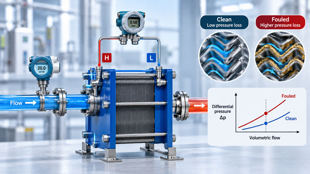
A plate heat exchanger in an industrial cooling system suddenly shows an increased differential pressure. While 40 kPa was measured during commissioning, the current value is 58 kPa. The maintenance team suspects fouled plates and plans to clean the heat exchanger.
However, an additional flow measurement shows that the volumetric flow rate has also increased. This raises an important question: Is the heat exchanger actually fouled, or is the higher pressure drop solely caused by the changed operating conditions?
An increasing differential pressure is not automatically proof of fouling. In many heat exchangers, pressure drop changes significantly with volumetric flow rate. Viscosity, temperature, gas content and flow distribution also influence the result.
For reliable condition assessment, differential pressure and actual volumetric flow rate must therefore be considered together. Temperature measurements on both sides also help identify possible deterioration in heat transfer.
This technical article explains the measuring principle, the correct connection of a differential pressure transmitter and the evaluation of changing pressure drops. A calculation example shows how measured values can be normalized to a common reference volumetric flow rate.
Table of Contents
- Measurement Task and Typical Misinterpretations
- Measuring Differential Pressure Across a Heat Exchanger
- Relationship Between Pressure Drop and Volumetric Flow Rate
- How Fouling Changes Pressure Drop
- Identifying Changes in Volumetric Flow Rate
- Temperature Effects and Viscosity
- Reference Characteristic of a Clean Heat Exchanger
- Practical Example: Fouling or Flow Rate Change?
- Measuring Points Upstream and Downstream of the Heat Exchanger
- Correctly Selecting a Differential Pressure Transmitter
- Considering Static Pressure and Overload
- Impulse Lines and Valve Manifolds
- Adding Suitable Flow Measurement
- Evaluating Temperatures and Heat Transfer Rate
- Hydraulic and Thermal Fouling
- Measurement Signals and PLC Integration
- Alarm Limits and Condition Indicators
- Calibration and Measurement Uncertainty
- Operational Safety and Maintenance
- Systematic Testing Procedure
- Typical Faults and Diagnostics
- Suitable ICS Products
- Conclusion
- Frequently Asked Questions
1. Measurement Task and Typical Misinterpretations
The differential pressure across a heat exchanger describes the pressure drop of the flowing medium between two defined measuring points.
It is frequently used to monitor flow resistance, blockages and fouling.
A typical misinterpretation occurs when two pressure readings are compared even though the volumetric flow rates or temperatures differ.
For diagnosis, the operating conditions must be comparable or appropriately accounted for during evaluation.
2. Measuring Differential Pressure Across a Heat Exchanger
A differential pressure transmitter has two pressure connections. The high-pressure connection H or (+) is connected to the designated measuring point upstream of the heat exchanger. The low-pressure connection L or (-) is connected to the corresponding measuring point downstream.
For the normal flow direction:
Δp = pInlet – pOutlet
Example: With an inlet pressure of 4.0 bar and an outlet pressure of 3.6 bar, the differential pressure is 0.4 bar or 40 kPa.
It is important that both pressure connections measure the same fluid side of the heat exchanger. The primary and secondary circuits must not accidentally be connected to one another.
3. Relationship Between Pressure Drop and Volumetric Flow Rate
The pressure drop of a heat exchanger depends significantly on the flow velocity.
With constant geometry, density and approximately turbulent flow conditions, the following relationship may apply as an approximation:
Δp ∝ V̇²
If the volumetric flow rate doubles, the pressure drop may increase fourfold in this simplified model.
Under laminar flow conditions, the relationship is often approximately linear. Real plate heat exchangers also have complex flow channels. The actual characteristic curve must therefore be considered.
| Change | Possible Effect on Δp | Diagnostic Indication |
|---|---|---|
| Volumetric flow rate increases | Pressure drop often increases | Not automatically proof of fouling |
| Volumetric flow rate decreases | Pressure drop often decreases | Fouling may be concealed |
| Flow channels become narrower | Resistance increases at the same volumetric flow rate | Indication of deposits or blockage |
| Viscosity increases | Pressure drop may increase | Check temperature and medium |
| Gas content or two-phase flow | Measured value and pressure drop may fluctuate | Check degassing and operating conditions |
| Valve position changes | Volumetric flow rate and pressure distribution change | Check flow path and measuring points |
4. How Fouling Changes Pressure Drop
In a fouled heat exchanger, deposits may form on the heat transfer surfaces or individual flow channels may become blocked.
This can change the available flow cross-section, surface roughness and flow distribution.
At the same volumetric flow rate, a higher pressure drop may therefore occur.
However, not every deposit that affects heat transfer necessarily causes an equally significant hydraulic change.
5. Identifying Changes in Volumetric Flow Rate
Higher differential pressure can result solely from a pump delivering more liquid through the heat exchanger.
Conversely, a fouled heat exchanger can reduce the volumetric flow rate at an unchanged pump speed. In this case, the measured differential pressure does not necessarily increase.
Therefore, the statement “Differential pressure is unchanged, so the heat exchanger is clean” is not reliable.
For condition assessment, the actual volumetric flow rate should ideally be measured independently of differential pressure.
6. Temperature Effects and Viscosity
Viscosity influences the flow resistance of a heat exchanger.
For many liquids, dynamic viscosity decreases as temperature increases. This can change the pressure drop even if the heat exchanger remains completely clean.
Temperature must therefore be considered during evaluation, particularly with oils, glycol mixtures and viscous process media.
A simple quadratic flow correction is only permissible when the underlying conditions are sufficiently comparable.
7. Reference Characteristic of a Clean Heat Exchanger
For long-term condition monitoring, a reference characteristic should be recorded after commissioning or cleaning.
For this purpose, differential pressure and volumetric flow rate are measured under defined operating conditions.
The characteristic curve may be based either on suitable manufacturer data or documented measurements of a demonstrably clean heat exchanger.
Important accompanying information includes the medium, temperature, density, viscosity and valve position.
Subsequent measured values can then be compared with the expected pressure drop under comparable conditions.
8. Practical Example: Fouling or Flow Rate Change?
A hypothetical plate heat exchanger operates with water. After cleaning, a differential pressure of 40 kPa was measured at 20 m³/h.
Several months later, the volumetric flow rate is only 16 m³/h. The measured differential pressure is 38 kPa.
Is the heat exchanger fouled?
8.1 Initial Data
- Reference volumetric flow rate: 20 m³/h.
- Reference differential pressure: 40 kPa.
- Current volumetric flow rate: 16 m³/h.
- Current differential pressure: 38 kPa.
- Same liquid with approximately unchanged physical properties.
- A quadratic pressure drop characteristic is assumed for the calculation model.
8.2 Calculating the Expected Pressure Drop
For the simplified characteristic curve:
ΔpExpected = ΔpReference · (V̇Current / V̇Reference)²
ΔpExpected = 40 kPa · (16 / 20)²
ΔpExpected = 25.6 kPa
In this model, a pressure drop of 25.6 kPa would therefore be expected if the hydraulic condition remained unchanged.
8.3 Comparing the Actual Pressure Drop
However, the measured value is 38 kPa.
The deviation is:
38 – 25.6 = 12.4 kPa
The relative difference compared with the expected value is:
12.4 / 25.6 · 100% = 48.4%
At this volumetric flow rate, the measured pressure drop is therefore 48.4% higher than the expected value from the reference characteristic.
8.4 Normalizing to the Reference Volumetric Flow Rate
Alternatively, the current pressure drop can be converted to the original reference volumetric flow rate:
ΔpNormalized = ΔpCurrent · (V̇Reference / V̇Current)²
ΔpNormalized = 38 kPa · (20 / 16)²
ΔpNormalized ≈ 59.4 kPa
Compared with the original 40 kPa, this corresponds to a significantly increased hydraulic resistance in the simplified model.
8.5 Comparing Different Operating Conditions
| Operating Condition | Volumetric Flow Rate | Expected Δp | Measured Δp | Evaluation |
|---|---|---|---|---|
| Clean reference | 20 m³/h | 40.0 kPa | 40.0 kPa | Reference condition |
| Lower flow, assumed clean | 16 m³/h | 25.6 kPa | 25.6 kPa | Change explained by volumetric flow rate |
| Lower flow, unusually high resistance | 16 m³/h | 25.6 kPa | 38.0 kPa | 48.4% above reference characteristic |
| Higher flow, assumed clean | 24 m³/h | 57.6 kPa | 57.6 kPa | Higher pressure drop explained solely by increased flow |
8.6 Interpreting the Result
Although the currently measured differential pressure of 38 kPa is below the original reference value of 40 kPa, it is unusually high considering the reduced volumetric flow rate.
The measurement indicates increased hydraulic resistance, for example due to deposits or narrowed flow channels.
However, it proves neither a particular deposit thickness nor a specific cause. Changes in viscosity, measurement conditions or the flow section must also be ruled out.
Important: The quadratic approximation and all measured values are hypothetical. Real heat exchangers require suitable characteristic curves and comparison conditions.
9. Measuring Points Upstream and Downstream of the Heat Exchanger
The pressure measuring points should cover the hydraulic resistance of the intended heat exchanger section.
If filters, control valves or long pipelines are also located between the pressure connections, their pressure losses will influence the measurement result.
For plate heat exchangers, the actual channel arrangement and connection positions must be considered.
The measuring points should be permanently and clearly identified and documented.
10. Correctly Selecting a Differential Pressure Transmitter
The measuring range should cover the normal pressure drop with sufficient resolution while also accounting for possible operating deviations.
For an expected range of 20 to 70 kPa, for example, a suitably configurable differential pressure transmitter may be appropriate depending on the application.
Important selection criteria include accuracy, static pressure, overload resistance, medium temperature, materials and output signal.
A linear differential pressure value is normally required for continuous fouling monitoring. Square-root characteristics, as used in certain differential-pressure-based flow measurements, must not be applied without consideration to direct pressure drop monitoring.
11. Considering Static Pressure and Overload
A heat exchanger may operate at several bar of system pressure while the differential pressure is only a few hundred millibar.
The transmitter must therefore withstand not only the small differential pressure but also the common static pressure present at both connections.
During startup, isolation or venting, temporarily unequal pressures may occur at the two inputs.
The permissible one-sided overload and the correct operating procedure for valve manifolds are therefore important.
12. Impulse Lines and Valve Manifolds
For liquid media, impulse lines must be designed to minimize the influence of uncontrolled gas pockets and deposits on the measurement result.
Different installation heights and hydrostatic pressure components can cause additional zero-point shifts.
A suitable three- or five-valve manifold facilitates controlled isolation, pressure equalization and certain testing and maintenance operations.
Operation must follow the specified sequence. In particular, the transmitter must not be subjected to impermissible one-sided overload during valve operation.
13. Adding Suitable Flow Measurement
An independent flowmeter provides the second important parameter for condition assessment.
For suitable liquids, a clamp-on ultrasonic flowmeter can be used, for example.
Its advantage: Under suitable pipe and operating conditions, the volumetric flow rate can be measured without additional intervention in the pipeline.
The instrument must be suitable for the medium, pipe material, flow profile and required measuring range.
14. Evaluating Temperatures and Heat Transfer Rate
To evaluate heat transfer, temperatures should be measured at the inlet and outlet of both heat exchanger circuits.
For single-phase liquid flow, the transferred heat rate can be approximated by:
Q̇ = ṁ · cp · ΔT
The calculation requires mass flow rate, specific heat capacity and temperature difference.
Deteriorating heat transfer may become apparent through changes in outlet temperatures or insufficient transferred heat. Here too, the process load and other operating conditions must be considered.
15. Hydraulic and Thermal Fouling
Hydraulic fouling describes an increase in flow resistance, for example due to narrowed channels.
Thermal fouling describes deterioration in heat transfer, for example due to a deposit layer with poor thermal conductivity.
Both effects can occur together but do not necessarily develop to the same extent.
A heat exchanger may therefore already show signs of thermal deterioration even though the normalized differential pressure does not yet indicate a clear change.
16. Measurement Signals and PLC Integration
Typical differential pressure transmitters provide a 4–20 mA signal and, where applicable, digital diagnostic information via HART.
The measuring range, unit, scaling and damping must be configured correctly for evaluation.
Differential pressure should be recorded together with volumetric flow rate, temperature and operating status.
This enables long-term trends to be evaluated under comparable operating conditions.
17. Alarm Limits and Condition Indicators
A fixed differential pressure limit may be useful for simple monitoring applications.
However, when volumetric flow rates fluctuate significantly, a condition-dependent limit is often more informative.
For example, the currently measured pressure drop can be compared with the expected value from the clean reference characteristic.
The ratio ΔpMeasured / ΔpExpected can serve as a hydraulic condition indicator, provided the conditions underlying the characteristic curve are fulfilled.
A cleaning alarm should not be based solely on this ratio without checking plausibility and operating conditions.
18. Calibration and Measurement Uncertainty
Calibration of the differential pressure transmitter must take the actual measuring range into account.
At smaller differential pressures and higher static pressures, zero-point deviations and static pressure effects can be relevant.
The uncertainty of the independent flow measurement also influences the normalized pressure drop evaluation.
Before evaluating small changes, the complete measurement chain and the repeatability of comparative measurements should therefore be checked.
19. Operational Safety and Maintenance
Heat exchangers may be pressurized and contain hot, cold or hazardous media.
Work on impulse lines, valve manifolds and measuring connections must only be carried out under the specified safe conditions.
The permissible pressure and temperature limits of the heat exchanger must be observed.
Increasing hydraulic resistance may need to be limited during operation. Decisions concerning cleaning, flushing or disassembly must follow manufacturer specifications and process conditions.
20. Systematic Testing Procedure
The following procedure is recommended for traceable condition monitoring:
- Record heat exchanger type, medium and operating data.
- Define measuring points upstream and downstream of the heat exchanger.
- Determine differential pressure range and static pressure.
- Select media-compatible connections and lines.
- Provide independent flow measurement.
- Measure the relevant temperatures.
- Check the measurement chain and scaling.
- Document the clean reference characteristic.
- Define comparison conditions and diagnostic limits.
- Check trend monitoring and maintenance decisions.
21. Typical Faults and Diagnostics
Increasing differential pressure at a higher volumetric flow rate may be normal. The decisive factor is comparison with the clean reference characteristic.
An unusually high pressure drop at a lower volumetric flow rate, on the other hand, may indicate deposits or narrowed flow channels.
If measured values fluctuate, gas pockets, impulse lines, pump pulsations and transmitter damping should be checked.
If heat transfer performance deteriorates while differential pressure changes very little, thermal deposits or changed operating conditions may be present.
22. Suitable ICS Products
ICS Schneider Messtechnik offers various differential pressure transmitters, pressure gauges and flowmeters for industrial heat exchanger systems.
| Product | Important Features | Typical Application |
|---|---|---|
| IDM331 | Differential pressure 20 mbar to 16 bar, accuracy 0.5% FSO, wet/wet | Compact differential pressure measurement with suitable liquids |
| IDPT200 | Differential pressure 1 mbar to 20 bar, static pressure up to 400 bar depending on configuration, HART | Continuous process monitoring |
| Siemens SITRANS P320 | Digital process transmitter, HART, diagnostics according to NAMUR NE107 | Differential pressure monitoring with control system integration |
| WIKA 732.14 / 762.14 | Mechanical differential pressure indication for elevated static pressures | Local monitoring and maintenance |
| Siemens SITRANS FS220 | Clamp-on ultrasonic flow measurement for liquids | Independent volumetric flow measurement |
22.1 IDM331
The IDM331 is a compact differential pressure transmitter for suitable liquids and gases. It features a measuring cell that can be pressurized from both sides and stainless steel separating diaphragms.
When selecting the instrument, the measuring span, permissible static pressure and specific media compatibility must be checked.
22.2 IDPT200
The IDPT200 is designed for industrial process differential pressure measurements. It supports HART communication and is available with different measuring cells and process connection variants.
The linear differential pressure output is relevant for direct pressure drop monitoring.
IDPT200 – ICS Process Transmitters
22.3 Siemens SITRANS P320
The SITRANS P320 offers differential pressure measurement, HART communication and extensive diagnostic functions, among other features.
The available measuring cells, materials and diaphragm seal configurations may be relevant for demanding heat exchanger applications.
SITRANS P320 – Product Information
22.4 WIKA 732.14 / 762.14
The differential pressure gauges of the 732.14 and 762.14 series are suitable for local indication in appropriate process applications.
They feature a robust metallic measuring chamber design and are available in configurations for high static operating pressures.
WIKA Differential Pressure Gauges – Product Information
22.5 Siemens SITRANS FS220
The SITRANS FS220 measures the volumetric flow rate of suitable liquids using clamp-on ultrasonic technology.
In combination with a differential pressure transmitter, it can help distinguish between changes in volumetric flow rate and increased flow resistance.
SITRANS FS220 – Product Information
Additional Pressure Measuring Instruments at ICS Schneider Messtechnik
23. Conclusion
Increasing differential pressure across a heat exchanger may indicate fouling, but it is not necessarily caused by deposits.
Volumetric flow rate, temperature, viscosity and flow conditions significantly influence pressure drop.
For reliable diagnostics, differential pressure and volumetric flow rate should be measured together and compared with a documented clean reference characteristic.
Temperature measurements complement the hydraulic assessment by providing information about actual heat transfer.
The decisive factor is not the highest differential pressure, but the deviation from the expected pressure drop under comparable operating conditions.
24. Frequently Asked Questions
24.1 Why Is Differential Pressure Measured Across a Heat Exchanger?
It allows the hydraulic resistance between the inlet and outlet to be monitored. Changes may indicate different flow conditions or fouling.
24.2 Does Increasing Differential Pressure Always Mean Fouling?
No. A higher volumetric flow rate can also cause an increased pressure drop. Viscosity and temperature additionally influence the result.
24.3 Why Does Pressure Drop Change with Volumetric Flow Rate?
In many turbulent flow conditions, pressure drop increases approximately with the square of the volumetric flow rate. The actual relationship is determined by the heat exchanger characteristic curve.
24.4 Can a Fouled Heat Exchanger Show a Lower Differential Pressure?
Yes. If increased flow resistance significantly reduces the volumetric flow rate, the measured differential pressure can decrease despite fouling.
24.5 How Can Hydraulic Fouling Be Detected?
By comparing the measured differential pressure with the expected value at the same volumetric flow rate and under comparable medium conditions.
24.6 What Is a Clean Reference Characteristic?
It describes the pressure drop of a clean heat exchanger as a function of volumetric flow rate under defined operating conditions.
24.7 Can Differential Pressure Be Converted to Another Volumetric Flow Rate?
Yes, using a suitable hydraulic model. However, quadratic conversion is only a permissible approximation under appropriate flow and medium conditions.
24.8 Which Differential Pressure Transmitter Is Suitable?
This depends on the measuring range, static pressure, medium and temperature. Suitable configurations of the IDM331, IDPT200 or SITRANS P320 may be considered, for example.
24.9 Why Is Static Pressure Important?
Even with a small differential pressure, both measuring connections may be exposed to high operating pressure. The transmitter must be designed accordingly.
24.10 Where Are the Pressure Connections Installed?
The H connection is connected to the designated inlet measuring point, and the L connection to the outlet measuring point on the same fluid side.
24.11 Why Is an Additional Flowmeter Required?
Only by knowing the actual volumetric flow rate can it be determined whether a change in pressure drop results from a new operating point or increased hydraulic resistance.
24.12 Is a Clamp-On Flowmeter Suitable?
Yes, with suitable liquids, pipe conditions and measuring ranges. One example is the Siemens SITRANS FS220.
24.13 What Role Does Temperature Play?
Temperature often influences the viscosity of the medium. It also provides important information about heat transfer.
24.14 Is Higher Pressure Drop Always Associated with Poorer Heat Transfer?
No. Hydraulic and thermal changes can occur to different extents. Both characteristics should therefore be monitored.
24.15 Can Differential Pressure Be Calculated Using Two Pressure Sensors?
Yes. However, for small pressure differences at higher operating pressure, the difference can be significantly affected by the measurement errors of both sensors.
24.16 Why Does the Differential Pressure Reading Fluctuate?
Possible causes include pump pulsations, gas pockets, varying volumetric flow rates or problems with the pressure impulse lines.
24.17 When Should a Heat Exchanger Be Cleaned?
When the documented hydraulic or thermal condition limits are exceeded and a suitable diagnosis shows that cleaning is necessary.
24.18 What Information Does ICS Need to Prepare a Quotation?
The required information includes the medium, temperature, operating pressure, expected differential pressure, volumetric flow rate, process connections, materials, desired output signal and installation conditions.