


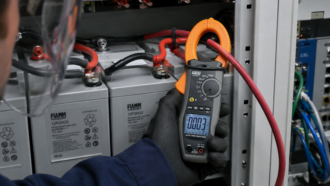
An AC/DC current clamp allows the current in a conductor to be measured without disconnecting the circuit. This is particularly useful for battery systems, UPS systems, DC drives, chargers and industrial DC links.
However, measuring direct current with a clamp differs significantly from conventional alternating-current measurement. The zero point must be checked before every measurement. The current direction, external magnetic fields, possible residual magnetisation of the clamp and the position of the conductor inside the clamp opening also influence the result.
Especially with small DC currents, even a minor zero-point error can account for a significant proportion of the displayed value. A current clamp designed for 1,000 A is therefore not automatically suitable for accurately measuring a few milliamperes.
This article explains how AC and DC current clamps work, how to perform zero adjustment correctly and how charging and discharging currents, drive currents and small direct currents can be assessed reliably.
Table of contents
- Why not every current clamp can measure direct current
- How a Hall-effect current clamp works
- Zero adjustment before DC measurement
- Residual magnetisation and external magnetic fields
- Correctly interpreting current direction and polarity
- Enclosing only one individual conductor
- Conductor position and fully closed clamp jaws
- Measuring battery charging and discharging current
- Direct current and mixed signals in drive systems
- Measuring range, resolution and accuracy
- Why small DC currents are particularly demanding
- Safety in battery and DC systems
- Systematic measurement procedure
- Typical errors when measuring DC current
- Practical example: Checking the quiescent current of a battery system
- Which measuring instruments / products are suitable?
- Conclusion
- Frequently asked questions about AC/DC current clamps
Why not every current clamp can measure direct current
A basic AC current clamp usually operates according to the transformer principle. The conductor being measured forms the primary winding of a current transformer. Because a transformer requires a changing magnetic field, this measuring principle cannot detect constant direct current.
Such current clamps are suitable only for AC signals. This also applies to many flexible Rogowski current sensors. They are particularly practical for large conductors and high alternating currents, but normally cannot measure a constant DC component.
Direct-current measurement requires a current clamp with additional magnetic-field-sensitive sensor technology. A Hall sensor is frequently used for this purpose.
An AC/DC current clamp can therefore measure:
- constant direct current
- alternating current
- mixed AC/DC signals, depending on the device version
- positive and negative current direction
The “AC/DC” designation must explicitly apply to the current measuring range. A clamp may, for example, measure AC current and additionally measure AC/DC voltage using test leads without being suitable for DC current measurement.
How a Hall-effect current clamp works
The current in the conductor generates a magnetic field. The magnetic core of the current clamp guides this field to the Hall sensor, which converts it into an electrical signal. The measuring instrument then converts this signal into a current value.
Because the Hall sensor also detects a static magnetic field, the clamp can measure direct current. At the same time, however, the system also responds to unwanted magnetic influences.
These include, for example:
- residual magnetisation of the clamp core
- nearby heavily loaded conductors
- motors, transformers and inductors
- permanent magnets
- changes in orientation within the Earth’s magnetic field
- temperature changes in the sensor electronics
A DC current clamp therefore requires zero adjustment. With alternating current, a constant offset is largely suppressed. With direct current, however, it would be added directly to or subtracted from the measured value.
Zero adjustment before DC measurement
Before measuring direct current, the display must be set to zero with the clamp head closed and no current-carrying conductor inside the clamp.
A suitable procedure is:
- Select the appropriate DC current measuring range.
- Close the clamp jaws completely.
- Ensure that there is no current-carrying conductor inside the clamp.
- Hold the clamp as far as possible in the same position in which the measurement will subsequently be performed.
- Maintain sufficient distance from motors, transformers and heavily loaded conductors.
- Activate the ZERO or REL function.
- Check whether the display remains stable at zero or very close to zero.
Zero adjustment should be performed as close as possible to the actual measurement. If the clamp is subsequently rotated, moved to another measuring point or exposed to strong magnetic fields, the zero point may shift again.
During a longer series of measurements, it is advisable to check the zero point again from time to time. This is particularly important for small measured values or changing ambient temperatures.
The ZERO function only compensates for the current offset. It does not improve the fundamental accuracy or resolution of the selected measuring range.
Residual magnetisation and external magnetic fields
After measuring a high direct current, residual magnetisation may remain in the magnetic core of the clamp. If the clamp is then closed without a conductor, it may no longer display exactly zero.
Repeatedly opening and closing the clamp may also slightly change the displayed zero value. Before a precise measurement, the clamp should therefore be closed, held in a stable position and zeroed again.
An abnormal zero point may also be caused by an external magnetic field. Typical sources include:
- large DC busbars
- neighbouring battery main cables
- electric motors
- inductors and transformers
- magnetic tool holders
If the display changes significantly when the clamp is merely rotated or moved by a few centimetres, the measuring point should be checked for magnetic interference.
Zero adjustment directly next to a heavily loaded neighbouring conductor may be problematic. The external field is then stored as part of the zero point. If the clamp is subsequently moved to another position, an additional measurement error occurs.
Correctly interpreting current direction and polarity
With direct current, the current clamp can detect not only the magnitude but also the direction of current flow. For this purpose, it usually has an arrow or other marking on the clamp head.
If the actual current flows in the defined positive direction, a positive measured value is displayed. If the clamp is reversed or the current flow changes direction, the value becomes negative.
For a battery, the polarity therefore depends on two factors:
- orientation of the current clamp
- current charging or discharging condition
A negative sign does not automatically indicate a measurement error. It may indicate that the current is flowing opposite to the assumed direction.
Before the measurement, it should be defined which direction is considered positive. For example:
- positive = current from the battery to the load
- negative = current from the charger to the battery
The assignment can also be reversed. The important point is that the arrow direction and the polarity convention used are documented.
Enclosing only one individual conductor
For current measurement, the clamp must enclose only the individual outgoing or return conductor.
If the positive and negative conductors of a DC circuit are enclosed together, the currents flowing in opposite directions generate opposing magnetic fields. With identical current values, these fields almost completely cancel each other out.
The clamp then displays approximately zero even though a high current is flowing in the circuit.
The same applies to:
- multicore AC cables containing outgoing and return conductors
- complete battery connection cables containing both polarities
- cable bundles containing several current paths
Enclosing several conductors together is only useful when the current difference is intentionally being measured. For normal load-current measurement, one individual conductor must be clearly accessible.
Conductor position and fully closed clamp jaws
The conductor should be positioned as centrally as possible inside the clamp opening. Particularly with small currents, placing the conductor directly against one of the clamp jaws may cause an additional measurement error.
The jaws must be fully closed. Contamination, metal particles or a mechanically damaged clamp head may create an air gap and impair the magnetic circuit.
The following should therefore be checked before measurement:
- Are the contact surfaces clean?
- Does the clamp head close completely?
- Is only the intended conductor inside the opening?
- Is the conductor positioned as centrally as possible?
- Is the clamp clear of neighbouring busbars?
For comparative measurements, the clamp should always be positioned in a similar way. Otherwise, different conductor positions may create an apparent trend even though the actual current has not changed.
Measuring battery charging and discharging current
A typical application is the inspection of battery, UPS or energy-storage systems. The current clamp is placed around one individual battery main conductor.
This allows the following values to be measured, for example:
- charging current from a charger
- discharging current under load
- quiescent current of a switched-off system
- current in individual battery feeders
- current distribution in parallel battery branches
In parallel-connected battery systems, each branch should be measured individually. Different currents may indicate different internal resistances, contact problems or uneven states of charge.
A briefly high current when an inverter is switched on or a DC-link capacitor is charged is not the same as the continuous operating current. A clamp with a suitable inrush-current or peak function is required for such events.
For small quiescent currents, it must be checked whether the resolution and basic accuracy of the current clamp are sufficient. An instrument designed for currents up to 1,000 A is not automatically the best choice for measuring a quiescent current of only a few milliamperes.
Direct current and mixed signals in drive systems
Different current waveforms may occur in drive systems. The correct measuring point and measuring mode are therefore essential.
Typical measuring points include:
- DC supply of a DC motor
- battery cable of a mobile drive
- DC link of a frequency converter
- output of a pulsed motor controller
A direct current with superimposed AC components often flows in the DC link. A pure DC measuring mode may display only the DC component. For a complete assessment, an AC+DC or TRMS function may be required.
The output of a frequency converter or PWM controller does not carry a simple sinusoidal current. The switching frequency, pulse shape and bandwidth of the current clamp influence the result.
A conventional AC/DC current clamp may be suitable for an approximate current check. However, accurate analysis of motor power, PWM current or dynamic current waveforms may require a power analyser, a suitable current sensor or an oscilloscope with a current probe designed for the purpose.
Measuring range, resolution and accuracy
For a reliable measurement, the measuring range must match the expected current. The largest possible measuring range provides sufficient overload reserve, but often offers lower resolution.
The following terms must be distinguished when selecting the instrument:
- Measuring range: the highest current the instrument can measure
- Resolution: the smallest change the display can show
- Accuracy: the permissible deviation from the actual value
- Zero-point stability: the change in the displayed value without measuring current
A display with two decimal places does not automatically mean that the final displayed digit is measured with the same accuracy.
For a clamp with an accuracy specification consisting of a percentage of the measured value plus additional digits, the absolute error may be significant in relation to the measured value at low currents.
For comparative measurements, the same measuring range should be used wherever possible. Changing between ranges may alter both resolution and measurement uncertainty.
Why small DC currents are particularly demanding
At a current of 500 A, a zero-point error of 0.1 A is usually insignificant. At a quiescent current of 0.2 A, however, the same offset would already represent 50% of the actual value.
The following are therefore important for small DC currents:
- small measuring range
- high resolution
- stable zero point
- low sensitivity to external magnetic fields
- repeated zero adjustment
- reproducible conductor position wherever possible
For measurements in the milliampere range, a dedicated DC low-current or leakage-current clamp should be used. Alternatively, the circuit can be measured using a suitable multimeter or shunt, provided that safely disconnecting the circuit is possible and permissible.
A current clamp is particularly advantageous when the circuit must not be interrupted. For very small currents, however, a direct current measurement is often more accurate.
Safety in battery and DC systems
Even at apparently low voltages, battery systems can deliver very high short-circuit currents. Accidentally bridging a battery terminal can cause severe arcing, burns or molten tools within a very short time.
At higher DC voltages, a direct-current arc also has no natural zero crossing and can therefore be more difficult to extinguish than a comparable alternating-current arc.
At least the following must be checked before measurement:
- maximum system voltage
- expected current and possible short-circuit current
- measurement category and voltage rating of the instrument
- insulation condition of the current clamp
- required personal protective equipment
- sufficient distance from exposed terminals and busbars
The current clamp may only be held by its insulated handle. Jewellery, watches and uninsulated tools are particularly hazardous near exposed battery terminals.
For voltage measurements using test leads, the connection rules and measurement categories of the instrument also apply. A current measurement with the clamp closed is not equivalent to a direct voltage measurement on exposed contacts.
Systematic measurement procedure
- Define the measurement task: Determine the expected current, current waveform and required direction.
- Check the instrument: Verify AC/DC suitability, measuring range, measurement category and clamp opening.
- Select the measuring point: Identify one individual, safely accessible conductor.
- Select DC mode: Choose the appropriate current measuring range.
- Perform zero adjustment: Zero the clamp while closed and without a conductor.
- Orient the clamp: Position the arrow according to the defined positive current direction.
- Enclose the conductor: Position the conductor as centrally as possible and close the jaws completely.
- Allow the measured value to stabilise: Read the magnitude and polarity.
- Check plausibility: Compare the operating condition, charger, loads and expected current.
- Recheck the zero point: Remove the conductor after the measurement and check the zero indication.
If the final zero indication differs significantly from the initial value, the measurement should be repeated after carrying out zero adjustment again.
Typical errors when measuring DC current
| Error | Possible effect | Better approach |
|---|---|---|
| AC-only clamp used for direct current | No measured value or an incorrect value | Use a current clamp explicitly designed for AC/DC current measurement |
| Zero adjustment not performed | A constant offset distorts the measured value | Zero the clamp before every precise DC measurement |
| Positive and negative conductors enclosed together | The magnetic fields cancel, resulting in a value close to zero | Enclose only one individual conductor |
| Clamp rotated significantly after zero adjustment | The zero point changes due to external magnetic fields | Zero the clamp in its later measuring position |
| Arrow direction ignored | The polarity is interpreted incorrectly | Define the positive current direction in advance |
| Conductor positioned directly against one clamp jaw | Additional position-related error | Position the conductor as centrally as possible |
| Large measuring range used for a small quiescent current | Insufficient resolution and relative accuracy | Use a low-current clamp or a direct measuring method |
| DC mode used for a strongly pulsed current | The AC component is not taken into account | Check the waveform and use a suitable AC+DC mode |
Practical example: Checking the quiescent current of a battery system
A mobile machine discharges its battery within a few days even though it is switched off. The expected quiescent current is below 0.1 A.
First, a large AC/DC current clamp with a measuring range of up to 1,000 A is used. After zero adjustment, the display fluctuates between 0.0 and 0.2 A. This does not allow a clear distinction between an actual quiescent current of 30 mA and 150 mA.
The measurement is not fundamentally incorrect. However, the current being measured is too close to the resolution, offset and measurement uncertainty of the clamp being used.
A DC low-current clamp is therefore used for further troubleshooting. It displays a stable quiescent current of approximately 120 mA.
The circuit is narrowed down by disconnecting the fused branches one after another. After disconnecting a communication module, the quiescent current falls to the expected value.
The example shows that the maximum measuring range alone is not a suitable selection criterion. A 1,000 A clamp is useful for high battery and drive currents. For quiescent currents in the milliampere range, however, a more sensitive measuring solution is required.
Which measuring instruments / products are suitable?
The current clamps and flexible current sensors category contains solutions for AC and DC current measurements, high load currents, small leakage currents and large conductors and busbars.
HT9021 for AC/DC currents up to 1,000 A
The HT9021 AC/DC current clamp is suitable for service and maintenance measurements on battery systems, DC circuits, machinery and industrial loads.
It measures direct and alternating currents up to 1,000 A and has a clamp opening for conductors with a diameter of up to approximately 45 mm. TRMS measurement is available for AC signals.
In addition to current, the instrument can measure AC/DC voltage, resistance, frequency, capacitance and temperature using a type K probe, among other variables, when used with test leads.
The HT9021 is a suitable choice when a wide current range and a robust universal current clamp are required. For very small quiescent-current or leakage-current measurements, however, a dedicated low-current clamp should be selected.
Flexible current sensors for high alternating currents
Flexible Rogowski current sensors are suitable for large busbars, high alternating currents and confined installation conditions.
However, they are normally not suitable for constant direct current. An AC/DC current clamp with a Hall sensor must therefore be used specifically for battery and DC applications.
Selecting the appropriate current clamp
The following information is particularly important for selection:
- AC, DC or mixed AC/DC signal
- smallest and largest expected current
- conductor diameter and available installation space
- system voltage and measurement category
- required resolution
- need for peak, inrush-current or data-logging functions
ICS Schneider Messtechnik assists with selecting a current clamp that matches the current range, signal waveform and electrical installation.
Conclusion: Zero point and measuring range are decisive for direct current
An AC/DC current clamp enables contactless measurement of battery, charging, drive and direct currents without disconnecting the circuit.
A Hall-effect current clamp is required for direct current. AC-only current clamps and most flexible Rogowski sensors cannot measure constant direct current.
Before every precise DC measurement, the clamp must be closed and zeroed without a current-carrying conductor inside it. Subsequent orientation, external magnetic fields and possible residual magnetisation may influence the zero point.
The current clamp may enclose only one individual conductor. If the outgoing and return conductors are enclosed together, their magnetic fields largely cancel each other out.
The polarity indicates the current direction relative to the arrow direction on the clamp. With batteries, this allows charging and discharging to be distinguished, provided that the positive direction has been clearly defined beforehand.
A robust 1,000 A clamp is suitable for high battery and drive currents. Small quiescent currents in the milliampere range, however, require a more sensitive low-current clamp or a suitable direct measuring method.
Frequently asked questions about AC/DC current clamps
Can every current clamp measure direct current?
No. Direct current requires an AC/DC current clamp with suitable magnetic-field-sensitive sensor technology. A transformer-based or Rogowski clamp normally measures alternating current only.
Why must a DC current clamp be zeroed?
The Hall sensor also detects static external fields and possible magnetic offset. Without zero adjustment, this value is added to the actual measured current.
How is zero adjustment performed?
The clamp is fully closed without a current-carrying conductor and set to zero using the ZERO or REL function, preferably while held in the same position in which the measurement will subsequently be made.
Why does the clamp display a small current without a conductor?
Possible causes include residual magnetisation, external magnetic fields, temperature drift or failure to repeat zero adjustment.
What does a negative sign mean?
The current is flowing opposite to the positive direction defined on the clamp. Depending on its orientation, this may indicate charging or discharging of a battery.
May the clamp enclose the positive and negative conductors at the same time?
Not for normal current measurement. The magnetic fields of the opposing currents largely cancel each other out, so the display may be close to zero.
Why should the conductor be positioned centrally inside the clamp?
A central position reduces the influence of conductor placement and improves reproducibility, particularly at low currents.
Can a 1,000 A current clamp measure a quiescent current of only a few milliamperes?
Usually not with sufficient accuracy. A DC low-current clamp or a suitable direct current measurement is required for this purpose.
Can a flexible Rogowski coil measure battery current?
Normally not if the current is constant direct current. Rogowski coils respond to currents that change over time and are mainly used for AC and pulse measurements.
In which direction must the arrow on the current clamp point?
This depends on the desired polarity convention. The arrow frequently points from the source to the load. The important point is to document the chosen direction.
What must be considered when measuring current on a frequency converter?
The DC link and motor output have different signal waveforms. The measuring mode, bandwidth and suitability of the current clamp must be checked for PWM and mixed signals.
Which information does ICS Schneider require for selection?
The signal type, smallest and largest current, system voltage, conductor diameter, measurement category, required resolution and requirements for peak, inrush-current or recording functions are needed.