


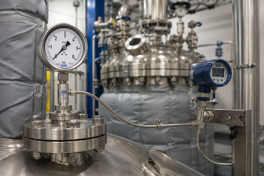
When designing a diaphragm-seal system, the diaphragm material is often the first consideration. However, the fluid located between the diaphragm and the pressure-measuring instrument is at least equally important. It hydraulically transmits the process pressure to the pressure gauge, pressure sensor or process transmitter.
An unsuitable filling fluid can lead to slow response, temperature-dependent zero-point shifts, unstable measured values or complete failure of the measurement. Low temperatures, high process temperatures, vacuum, very small measuring ranges and applications involving oxygen, food or pharmaceuticals are particularly critical.
The filling fluid must therefore not be selected in isolation. The diaphragm diameter, measuring range, capillary length, installation position, process pressure and temperature profile together form a closed measuring system.
This article explains which properties of the filling fluid are decisive, why vacuum applications require particularly careful examination and when silicone oil, halocarbon or food-grade fluids may be suitable.
Table of contents
- What function the filling fluid performs
- Which information is required for selection
- Temperature range and thermal expansion
- Viscosity and response time
- Why vacuum presents special requirements
- Considering the process medium and diaphragm rupture
- Oxygen and chlorine applications
- Food, pharmaceutical and biotechnology applications
- Silicone-free and high-purity processes
- Direct mounting, cooling element or capillary line
- Height difference and additional hydrostatic pressure
- Typical measuring errors caused by incorrect design
- Systematic selection of the filling fluid
- Practical example: Pressure measurement on a heated vacuum vessel
- Which measuring instruments / products are suitable?
- Conclusion
- Frequently asked questions about diaphragm-seal filling fluids
What function the filling fluid performs
The diaphragm of the diaphragm seal separates the process medium from the actual pressure-measuring instrument. Behind the diaphragm is a cavity completely filled with fluid.
When process pressure acts on the diaphragm, it is deflected slightly. This change in volume is transmitted through the filling fluid to the measuring element of the connected pressure gauge or transmitter.
For this purpose, the filling fluid must:
- transmit the pressure with as little loss as possible
- remain liquid throughout the entire temperature range
- have sufficiently low compressibility
- be suitable for the pressure and vacuum range
- be compatible with the internal system materials
- be suitable for the application in the event of possible diaphragm damage
The diaphragm seal, filling fluid, capillary line and measuring instrument form a closed system. Filling or sealing screws must not be opened. Even small losses of fluid or trapped gas bubbles can impair the measuring function.
Which information is required for selection
The designation of the process medium alone is not sufficient for the design. At least the following information is required for a reliable selection:
- minimum and maximum process pressure
- absolute pressure for vacuum applications
- minimum and maximum process temperature
- ambient temperature at the measuring instrument and along the capillary
- measuring range and required accuracy
- diaphragm-seal design and diaphragm diameter
- direct mounting, cooling element or capillary length
- height difference between the diaphragm seal and measuring instrument
- requirements arising from food, pharmaceutical, oxygen or hazardous-area applications
- cleaning and sterilisation conditions
The actual extreme conditions are decisive. A process that normally operates at 80 °C may briefly reach significantly higher temperatures during SIP cleaning. Likewise, a vessel may operate under a slight vacuum during normal operation, while a much lower absolute pressure occurs during cooling.
Temperature range and thermal expansion
Filling fluids change their volume with temperature. Because the diaphragm-seal system is closed, this change in volume causes an additional deflection of the diaphragm.
As the temperature rises, the fluid expands. The diaphragm is pushed towards the process, and the measuring instrument may indicate a positive zero-point shift. When the temperature falls, the fluid contracts, which may result in a negative zero-point shift.
The temperature influence increases, among other things, with:
- a large filling volume
- a long capillary line
- a small or stiff diaphragm
- a small pressure measuring range
- large temperature changes
- different temperatures along the system
A large diaphragm diameter can reduce temperature errors because a larger diaphragm generates less counterpressure for the same change in volume. The smallest possible internal filling volume is also beneficial.
The freezing, boiling or decomposition point stated in a filling-fluid table is not automatically the permissible operating range of the complete diaphragm-seal system. The diaphragm, pressure, vacuum, measuring range and installation type may further restrict the actual range.
Viscosity and response time
Viscosity describes the resistance of the filling fluid to flow. The higher the viscosity, the more slowly a pressure change may be transmitted through narrow channels and capillary lines.
At lower temperatures, many filling fluids become significantly more viscous. The fluid may still be physically liquid while the response time of the measuring system has already increased considerably.
The response time is influenced in particular by:
- viscosity of the filling fluid
- length and internal diameter of the capillary
- internal filling volume
- displacement volume of the measuring instrument
- diaphragm size and stiffness
- temperature of the complete system
A filling fluid for low temperatures is therefore not selected solely according to its freezing point. Its viscosity at the actual minimum temperature must also be taken into account.
For rapidly changing pressures, dosing processes or control loops, a short capillary line or direct mounting is usually advantageous. For slow vessel-pressure measurement, however, a longer response time may be acceptable.
Why vacuum presents special requirements
For vacuum applications, relative pressure alone is not decisive. The lowest absolute pressure must be known for the design.
As the absolute pressure falls, a filling fluid may begin to evaporate or release dissolved gases depending on its temperature. The resulting gas bubbles are considerably more compressible than the liquid and may cause the following problems:
- delayed pressure transmission
- unstable or fluctuating measured values
- failure to return to the zero point
- greater temperature dependence
- damage to or overloading of the diaphragm
A high boiling point at atmospheric pressure does not prove suitability for a hot vacuum. The evaporation behaviour changes at lower absolute pressure.
The following factors must therefore be assessed together when designing a vacuum system:
- minimum absolute pressure
- temperature at the diaphragm seal
- temperature along the capillary
- vapour pressure of the filling fluid
- installation position and height difference
- diaphragm diameter and measuring range
A filling fluid suitable for an oxygen application may be unsuitable for certain vacuum or absolute-pressure ranges. Approval must therefore always be based on the complete combination.
Considering the process medium and diaphragm rupture
During normal operation, the filling fluid does not come into contact with the process medium. However, if the diaphragm is damaged, it may enter the process.
The following must therefore be assessed:
- Can the filling fluid react dangerously with the process medium?
- May it contaminate the product?
- Can it damage downstream equipment or a catalyst?
- Are FDA, USP or other approvals required?
- Is a silicone-free version required?
- Must diaphragm rupture also be monitored?
The chemical resistance of the diaphragm and the suitability of the filling fluid must be considered separately. A corrosion-resistant Hastelloy or tantalum diaphragm does not automatically mean that any filling fluid is permissible for the process.
For toxic, highly reactive or particularly valuable products, a double-diaphragm system with diaphragm-rupture monitoring may be useful.
Oxygen and chlorine applications
Oxygen can react violently with oils, greases and other combustible substances. A conventional diaphragm-seal system filled with silicone oil must therefore not automatically be used in an oxygen application.
Depending on the manufacturer, suitable halocarbon filling fluids may be considered for such applications. The following are additionally required:
- a system version explicitly approved for oxygen
- oil- and grease-free cleaning
- suitable diaphragm and sealing materials
- compliance with permissible oxygen pressures and temperatures
- clean assembly and protected packaging
The permissible combinations of oxygen pressure and temperature are limited and must correspond to the manufacturer’s documentation or the relevant approval.
Halocarbon must not be regarded as a universal solution for every critical application. Depending on the instrument, its use may be excluded under vacuum or at very low absolute pressures.
Food, pharmaceutical and biotechnology applications
In hygienic processes, it must be considered that the filling fluid could enter the product if the diaphragm ruptures.
Depending on the operational and regulatory requirements, suitable options may include:
- food-grade glycerine fillings
- Neobee® M-20 or comparable approved fluids
- medical white oil
- other FDA- or pharmacopoeia-compliant filling fluids
A general description such as “food-grade oil” is not sufficient for approval. The exact fluid, its approvals and the permissible operating conditions must be documented.
For CIP and SIP processes, the normal product temperature is not the only relevant factor. The design must also consider the cleaning temperature, sterilisation duration, pressure and possible rapid temperature changes.
The hygienic process connection, surface quality and absence of dead spaces remain important components of the measuring point, regardless of the filling fluid.
Silicone-free and high-purity processes
In paint shops, semiconductor production, high-purity gas processes or certain pharmaceutical applications, even minor silicone contamination can be problematic.
A silicone-free filling fluid may then be required. Additional components of the system must also be considered, for example:
- assembly aids
- seals and lubricants
- cleaning procedures
- packaging and transport
- the operator’s contamination limits
Special high-purity fluids or water/alcohol mixtures may be specified for ultrapure-water or semiconductor processes. Limited temperature and pressure ranges also apply here.
Direct mounting, cooling element or capillary line
The mounting arrangement has a significant influence on temperature error and response time.
| Mounting arrangement | Advantage | Points to consider |
|---|---|---|
| Direct mounting | Small filling volume and fast response | The measuring instrument is exposed more strongly to the process temperature |
| Cooling element | Reduces the temperature at the measuring instrument | The installation position and heat dissipation must be suitable |
| Capillary line | Spatial and thermal separation | Larger filling volume, longer response time and influence of height difference |
The longest possible capillary is not automatically the best solution for a hot process. As the length increases, the filling volume, temperature influence and response time also increase.
Capillary lines should be routed with minimal vibration, protected against mechanical damage and not bent more tightly than permitted by the manufacturer.
Height difference and additional hydrostatic pressure
With a capillary line, the column of fluid generates additional hydrostatic pressure. This depends on the density and height difference:
Δp = ρ × g × h
If the measuring instrument is installed above the diaphragm seal, the indication may be lower than the process pressure. If it is installed below the diaphragm seal, the indication may be higher.
The effect is particularly relevant for:
- small measuring ranges
- high filling-fluid density
- long vertical capillary lines
- vacuum and absolute-pressure measurements
The height difference must be specified when ordering. The system can be calculated accordingly and, where applicable, supplied with an adjusted zero setting.
Typical measuring errors caused by incorrect design
| Observation | Possible cause | Check |
|---|---|---|
| Zero point changes with temperature | Thermal expansion of the filling fluid | Check the temperature profile, diaphragm diameter and filling volume |
| Measured value responds very slowly at low temperature | Viscosity too high | Reassess the filling fluid and capillary line |
| Unstable indication under vacuum | Gas formation or unsuitable vacuum design | Check absolute pressure, temperature and filling fluid |
| Pressure indication remains after the process has ended | Slow return, gas bubble or diaphragm overload | Have the complete system examined by the manufacturer |
| Large constant zero-point error | Height difference in the capillary | Compare density, installation height and factory design |
| Error after SIP cleaning | Temperature limit or thermal transition not considered | Include the cleaning cycle in the system design |
An existing diaphragm-seal system should not be opened, refilled or disassembled into individual components on site. Professional filling is performed under defined conditions and frequently under vacuum so that no air remains in the system.
Systematic selection of the filling fluid
- Record the process pressure: Specify the minimum, operating and maximum pressure, including the absolute vacuum value.
- Document the temperatures: Consider the process, environment, cleaning and shutdown conditions.
- Classify the application: Chemical, oxygen, food, pharmaceutical, high-purity medium or silicone-free process.
- Define the measuring requirements: Determine the measuring range, accuracy and required response time.
- Plan the mounting arrangement: Define direct mounting, cooling element, capillary length and height difference.
- Select the diaphragm: Match the material, diameter and process connection to the medium.
- Have the filling fluid verified: Assess the temperature, pressure, vacuum, viscosity and approvals together.
- Calculate the complete system: Consider the temperature error, response time and hydrostatic influence.
- Document the version: Record the filling fluid, installation position and operating limits in the documentation.
Practical example: Pressure measurement on a heated vacuum vessel
An absolute-pressure transmitter with a diaphragm seal is to be used on a process vessel. The normal process operates at 120 °C and approximately 150 mbar absolute. During cooling, the pressure may briefly fall to 40 mbar absolute.
Initially, a universal diaphragm-seal system with standard silicone oil and a long capillary line is planned.
During the technical review, however, several critical points are identified:
- The lowest absolute pressure was not stated in the original enquiry.
- The capillary line increases the filling volume and temperature influence.
- The small absolute-pressure measuring range is sensitive to thermal zero-point shifts.
- The vacuum suitability of the filling fluid must be checked separately at 120 °C.
The system is therefore not designed solely according to the nominal temperature. The manufacturer calculates the vacuum, temperature, diaphragm diameter, capillary length and required response time together.
As a result, the capillary is shortened, a larger diaphragm seal is selected and a filling fluid suitable for the specific absolute-pressure and temperature range is defined.
The example shows that the specification “−1 to 0 bar gauge” is not sufficient for vacuum design. The lowest absolute pressure together with the temperature occurring at that pressure is required.
Which measuring instruments / products are suitable?
The diaphragm seals category contains diaphragm and in-line seals with threaded, flanged and hygienic process connections, as well as versions with direct mounting, cooling elements or capillary lines.
Suitable measuring instruments can be found in the pressure sensors and differential-pressure sensors category.
WIKA DSS10T for general process applications
The WIKA DSS10T combines a pressure sensor with an attached threaded diaphragm seal.
The compact direct-mounted design has a comparatively small filling volume and is suitable for aggressive, corrosive or hot media in the process industry. The filling fluid and operating limits are selected to match the measuring task.
WIKA DSS26M for flanged connections
The WIKA DSS26M is a mechanical pressure gauge with an attached flanged diaphragm seal and an internally mounted, fully welded diaphragm.
It is particularly suitable for aggressive, highly viscous, crystallising or hot process media. In addition to the diaphragm material, the filling fluid, temperature and process pressure must also be coordinated.
WIKA 990.60 for sterile processes
The WIKA 990.60 has a hygienic NEUMO BioControl® connection and is designed for applications in the pharmaceutical and biotechnology industries.
Suitable approved filling fluids and versions for CIP and SIP processes can be selected specifically for such systems.
Individual design of the complete system
For a technical assessment, the medium, pressure range, lowest absolute pressure, process and ambient temperature, measuring instrument, connection, installation position, capillary length and special requirements relating to hygiene, oxygen or silicone-free operation are required.
ICS Schneider Messtechnik assists with the selection of the diaphragm seal, diaphragm material, filling fluid and measuring instrument, as well as the calculation of temperature influence and response time.
Conclusion: The filling fluid must match the complete diaphragm-seal system
The filling fluid is a functionally critical component of a diaphragm-seal system. It transmits the process pressure from the diaphragm seal to the measuring instrument and influences the temperature behaviour, response time and measuring error.
At high or low temperatures, both the physical operating limits and the viscosity and thermal expansion must be taken into account.
For vacuum applications, specifying the relative vacuum is not sufficient. The decisive factors are the lowest absolute pressure and the temperature occurring at the same time. An unsuitable fluid may release gas and impair pressure transmission.
In food, pharmaceutical and biotechnology processes, possible product contamination in the event of diaphragm rupture must be considered. Oxygen applications require specially approved and cleaned systems with clearly defined pressure and temperature limits.
The capillary length, diaphragm diameter, filling volume and height difference are also part of the design. A filling fluid therefore cannot be ordered or replaced independently of the rest of the measuring system.
The most reliable solution is achieved when all process and installation conditions are specified before manufacture and the complete diaphragm-seal system is calculated, filled and tested by the manufacturer.
Frequently asked questions about diaphragm-seal filling fluids
What function does the filling fluid perform in a diaphragm seal?
It hydraulically transmits the process pressure acting on the diaphragm to the connected pressure gauge or pressure transmitter.
Is silicone oil suitable for every diaphragm seal?
No. Silicone oil is suitable for many industrial applications, but may be unsuitable for oxygen, silicone-free processes, certain hygienic applications or special vacuum conditions.
Why does temperature change the measured value?
The filling fluid expands when heated and contracts when cooled. In the closed system, this may cause additional diaphragm deflection and therefore a zero-point error.
What happens at low temperatures?
The viscosity often increases significantly. As a result, the diaphragm-seal system may respond more slowly even though the fluid has not yet solidified.
Which specification is decisive for vacuum applications?
The lowest absolute pressure together with the temperature occurring at that pressure. A specification in bar gauge alone is not sufficient for the design.
Can halocarbon be used under vacuum?
Not in every case. Halocarbon is often used for specially approved oxygen applications but may be excluded for certain vacuum and absolute-pressure measuring ranges.
Which filling fluid is suitable for food applications?
Depending on the requirements, approved glycerine, Neobee or medical white-oil fillings may be suitable. The specific approval and operating range must be verified.
Does the capillary length influence the measurement?
Yes. A longer capillary increases the filling volume, response time, temperature influence and possible hydrostatic error.
Can a diaphragm-seal system be refilled on site?
Normally not. The system is filled completely and without bubbles under defined conditions. Opening it may permanently impair the measuring function.
Why must the height difference be specified?
The column of fluid in the capillary generates additional hydrostatic pressure, which is particularly relevant for small measuring ranges.
Is the temperature range of the filling fluid sufficient for selection?
No. The pressure, vacuum, diaphragm, measuring range, capillary, ambient temperature and required response time must also be taken into account.
Which information does ICS Schneider require for the design?
The process medium, pressure and absolute-pressure range, process and ambient temperature, connection, measuring instrument, installation position, capillary length, height difference and requirements relating to hygiene, oxygen, explosion protection or silicone-free operation are required.