


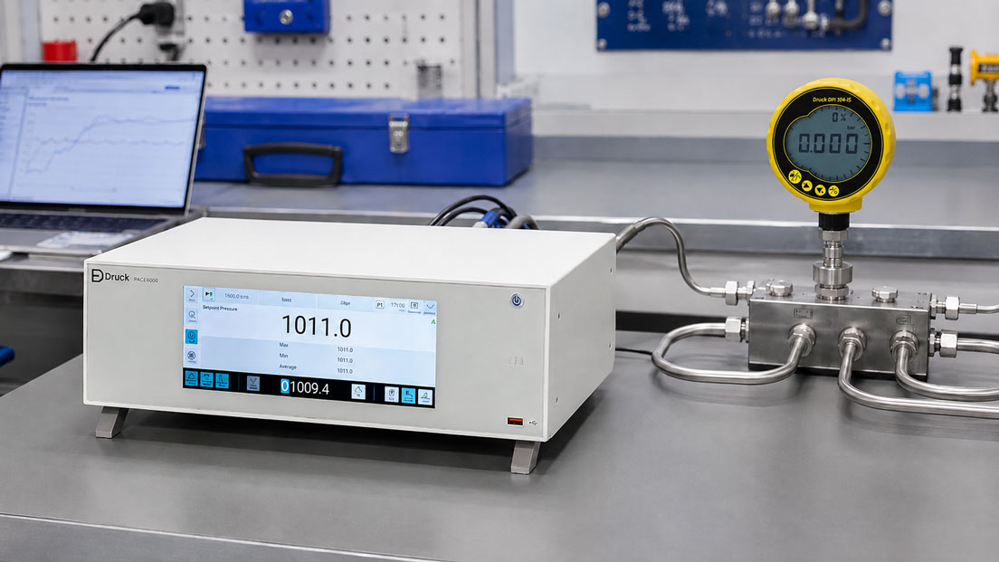
An automatic pressure controller should approach specified pressure points quickly, stably and reproducibly. In practice, however, the actual value may remain below the setpoint, repeatedly overshoot or require a very long time to fulfil the configured stability criterion.
The cause is not necessarily located inside the controller. Long hoses, large test volumes, flexible lines, leaking devices under test, trapped air or unsuitable control parameters change the dynamic behaviour of the complete pressure system.
For reliable diagnosis, the complete measurement and control chain must therefore be considered: pressure supply, controller, valves, hoses, adapters, device under test, venting and calibration software. Only when these components are technically compatible can the controller stabilise the setpoint quickly and without unnecessary overshoot.
Suitable systems can be found in the ICS category Pressure Regulators and Pressure Controllers. Software for automated test procedures and calibration documentation is grouped under Calibration Software.
Table of Contents
- How does an automatic pressure controller operate?
- Correctly distinguishing between typical fault patterns
- Checking the pressure supply and venting
- Why does the test volume affect pressure control?
- Keeping hoses and adapters as compact as possible
- Distinguishing leakage from normal stabilisation
- Accounting for volume expansion and mechanical movement
- Identifying temperature-related pressure changes
- Removing air and gas bubbles from hydraulic systems
- Configuring the control speed and pressure ramp
- Reducing overshoot selectively
- Defining the stability criterion and settling time
- Correctly switching external valves and manifolds
- Accounting for media cleanliness and contamination
- Programming robust automatic test sequences
- Systematic diagnostic procedure
- Practical example: Unstable transmitter calibration
- Typical errors involving automatic pressure controllers
- What should be included in the measurement documentation?
- Which products and solutions are suitable?
- Conclusion
- Frequently asked questions
How does an automatic pressure controller operate?
A pressure controller measures the pressure using an internal reference sensor and controls inlet and outlet valves so that the measured actual value follows the specified setpoint.
In simplified form, the control system consists of:
Pressure supply → control valves → internal volume → test line → device under test → reference sensor
During pressure generation, the controller opens the inlet valve. During pressure reduction, the test volume is depressurised through an outlet or vent valve. As the setpoint is approached, the valve movements become progressively smaller until the pressure remains within the defined control and stability band.
The controller does not regulate only the connected device under test, but the entire connected volume. This includes:
- internal channels and valves,
- test hoses,
- manifolds and adapters,
- measuring instruments and devices under test,
- unintentional dead volumes,
- external reference sensors where applicable.
If this volume changes or the system continuously loses pressure, the controller must constantly readjust.
Correctly distinguishing between typical fault patterns
| Fault pattern | Probable causes |
|---|---|
| Actual value remains significantly below the setpoint | Supply pressure too low, severe leakage, closed valve or insufficient controller capacity |
| Actual value increases only very slowly | Large test volume, long hoses, slow pressure ramp or limited supply flow rate |
| Pressure repeatedly overshoots | Excessively aggressive control, small volume, high pressure ramp or flexible device under test |
| Pressure falls after reaching the setpoint | Leakage, temperature equalisation, volume expansion or internal movement of the device under test |
| Pressure fluctuates around the setpoint | Unsuitable control parameters, pulsating supply, unstable temperature or sticking valve |
| Controller is stable, but the DUT indication drifts | Thermal stabilisation, damping or mechanical hysteresis of the device under test |
| Automatic sequence is aborted | Stability criterion not fulfilled within the maximum waiting time |
Before making any changes, it must be established whether the controller cannot generate the pressure, cannot regulate it stably or merely fails to fulfil the stability criterion defined in the software.
Checking the pressure supply and venting
A pneumatic controller requires a sufficiently high and stable pressure source. The supply pressure must be above the highest required test pressure and must provide sufficient reserve for valves, line losses and dynamic control processes.
If the reserve is too small, the inlet valve opens completely without the setpoint being reached. Typical causes include:
- supply regulator set too low,
- pressure drop in the gas cylinder during the test,
- pressure regulator with insufficient capacity,
- narrow or long supply line,
- simultaneous supply of additional consumers,
- contaminated filter,
- closed or only partially opened shut-off valve.
Pressure reduction also requires a free and sufficiently dimensioned vent path. A blocked outlet, high back pressure or an unsuitable shared vent line can prevent lower setpoints from being reached.
For vacuum or absolute-pressure applications, it must also be checked whether the vacuum source can achieve the required final pressure and the necessary volumetric flow rate.
Why does the test volume affect pressure control?
The larger the connected volume, the more gas or liquid must be supplied or removed to produce a specific pressure change. This increases pressure-generation, pressure-reduction and settling times.
The test volume includes not only the device under test, but also:
- hoses and pipework,
- manifold blocks,
- adapters,
- pressure gauges and reference instruments,
- unused connections that have not been isolated,
- internal valve cavities.
A controller that regulates a single pressure transmitter quickly may require significantly more time when connected to a manifold containing several devices under test.
A large volume is not inherently impermissible. However, it must be considered when selecting the controller, pressure ramp, valve configuration and maximum permissible settling time.
Very small volumes can also be problematic. Even a minor valve movement may cause a large pressure change, resulting in overshoot when aggressive control is used.
Keeping hoses and adapters as compact as possible
A long test hose increases the volume and may expand elastically under pressure. The controller must then not only compress the contained medium, but also deform the hose wall.
The following applies for a stable test arrangement:
- Select the shortest technically practical hose.
- Do not use an unnecessarily large internal diameter.
- Use low-volume test hoses suitable for the pressure range.
- Avoid flexible plastic hoses where high accuracy is required.
- Reduce adapter chains and unnecessary T-pieces.
- Seal unused connections with suitable closures.
- Avoid dead volumes behind closed valves.
Rigid stainless-steel lines normally exhibit less volume change than flexible hoses, but transmit vibrations and mechanical forces more strongly. The design must therefore be appropriate for the measuring task and test bench.
Distinguishing leakage from normal stabilisation
A leak causes the controller to supply medium continuously. With small leak rates, the setpoint may appear to have been reached while the inlet valve continuously readjusts. With larger leaks, the actual value remains below the setpoint or the stability condition is not fulfilled.
Typical leakage points include:
- insufficiently tightened fittings,
- damaged or incorrectly installed seals,
- unsuitable thread combinations,
- leaking quick couplings,
- open vent valves,
- leaking pressure switches or pressure gauges,
- porous hoses,
- internal leakage inside the device under test.
To isolate the cause, the system is shortened step by step:
- Operate the controller with a leak-tight closure.
- Connect and seal the test hose without the device under test.
- Add the manifold and adapters.
- Connect the devices under test individually.
This makes it possible to determine which component causes the control behaviour to become abnormal.
During a leak test, it must be considered that temperature and volume changes can also cause a pressure drop. A pressure change does not therefore automatically indicate an actual media leak.
Accounting for volume expansion and mechanical movement
In addition to external leakage, the enclosed volume may change during the test. Possible causes include:
- elastic expansion of hoses,
- deformation of diaphragms and bellows,
- movement of a piston,
- settling of seals,
- mechanical hysteresis of a pressure gauge,
- switching movement of a pressure switch.
These processes may be more pronounced during the first pressure cycle than during subsequent cycles. For some devices under test, preloading or a complete increasing and decreasing pressure cycle before the actual calibration may therefore be appropriate.
When a pressure switch is tested, movement of its switching element can cause a small change in volume. The controller must then stabilise again before the next measured value is recorded.
Identifying temperature-related pressure changes
In a closed gas volume, temperature directly influences the pressure. During a rapid pressure increase, the gas heats up as a result of compression. After the setpoint has been reached, the gas cools again, causing the pressure to fall.
During rapid pressure reduction, the gas may initially cool and subsequently warm up again. The pressure then changes even without any leakage.
This effect is particularly noticeable with:
- large pressure steps,
- small, enclosed volumes,
- high control speeds,
- long holding times,
- large temperature differences between the controller and device under test.
A slower pressure ramp and an appropriate stabilisation time reduce the thermal influence. The controller, hoses and devices under test should be allowed to reach ambient temperature before a precise calibration is performed.
Removing air and gas bubbles from hydraulic systems
In hydraulic pressure controllers, trapped air causes significantly increased compressibility. The pressure then rises slowly, rebounds or falls again after the pump stops.
Typical air pockets occur:
- after replacing the device under test,
- in elevated hose loops,
- in blind bores and adapters,
- in incompletely filled pressure gauges,
- because of leaking suction connections,
- because of outgassing from the test medium.
The hydraulic system must be filled and vented in accordance with the manufacturer’s instructions. Suitable collection containers and protective measures must be provided.
A hydraulic controller must not be operated with a different medium without approval. Oil, water and special fluids differ in terms of viscosity, material compatibility, compressibility and contamination risk.
Configuring the control speed and pressure ramp
Many pressure controllers offer different control modes or an adjustable pressure-change rate. Fast control reduces the test duration, but can cause overshoot with small volumes or sensitive devices under test.
A slower or more precise control mode is particularly suitable for:
- low measuring ranges,
- small test volumes,
- sensitive diaphragms,
- pressure switches with closely spaced switching points,
- devices under test with mechanical hysteresis,
- high accuracy requirements.
The pressure ramp is frequently specified as pressure per unit of time, for example bar/s or a percentage of the measuring range per second.
It must be suitable for both the controller and the device under test. An excessively fast ramp can:
- overshoot the setpoint,
- cause pressure switches to trip dynamically too early,
- overload devices under test,
- increase thermal effects,
- cause mechanical pointers to oscillate.
Reducing overshoot selectively
Overshoot means that the actual value initially exceeds the setpoint and subsequently has to be regulated back down.
Possible countermeasures include:
- reducing the pressure ramp,
- selecting the precise instead of the fast control mode,
- programming smaller setpoint steps,
- matching the control parameters to the connected volume,
- avoiding an unnecessarily high supply pressure,
- replacing highly flexible lines,
- preloading mechanically unstable devices under test.
A restrictor may only be used if it is intended by the manufacturer or approved for the specific test arrangement. An arbitrary capillary restrictor can slow down pressure control, create additional dead volumes or change the behaviour during pressure reduction.
For sensitive devices under test, an additional software pressure limit should be configured. However, it does not replace a mechanical overpressure-protection device.
Defining the stability criterion and settling time
Reaching the setpoint and reaching stability are two different conditions.
One possible stability criterion is, for example:
Pressure change within 10 seconds less than 0.01% of the measuring range
A complete criterion should include at least:
- permissible deviation from the setpoint,
- permissible pressure change or drift,
- observation period,
- maximum waiting time,
- number of required stable measured values.
An excessively strict criterion can unnecessarily extend or abort a technically valid test. An excessively generous criterion can allow measured values to be recorded while the device under test is still drifting.
The stability band should be appropriate for the uncertainty of the reference system and the permissible deviation of the device under test. It must not be configured more tightly than is reasonably supported by the resolution, control stability and environmental conditions.
Correctly switching external valves and manifolds
Automated test benches frequently contain additional solenoid valves, manifolds or switching blocks. Incorrect valve positions can block pressure generation or open unwanted parallel volumes.
The following must be checked:
- default position during a power failure,
- switching sequence,
- direction of flow,
- internal relief function,
- permissible differential pressures,
- electrical feedback of the valve position,
- connections to unused test stations.
A solenoid valve must not be switched at the same time as a large setpoint step if this abruptly changes the test volume. A new stabilisation phase must be allowed after every switching operation.
Accounting for media cleanliness and contamination
Pneumatic precision controllers require a clean, dry medium approved for the instrument. Particles, moisture or oil can affect the control valves and internal measuring channels.
Particularly critical sources include:
- unfiltered workshop compressed air,
- compressor oil and aerosols,
- condensate,
- particles from unsuitable hoses,
- backflow from contaminated devices under test,
- residues of foreign process media.
A device under test that was previously operated with oil, water or aggressive process media must not be connected directly to a pneumatic precision controller. Isolation devices, suitable media separators or special cleaning and flushing procedures may be required.
Programming robust automatic test sequences
An automatic calibration sequence should not only approach the setpoints, but also handle fault conditions in a controlled manner.
The following are typically defined for each measuring point:
- setpoint,
- pressure ramp,
- permissible setpoint deviation,
- stability criterion,
- minimum holding time,
- maximum settling time,
- number of measured-value recordings,
- behaviour in the event of a timeout.
If stability is not reached, a robust sequence can:
- extend the waiting time once,
- repeat the measuring point,
- reduce the pressure ramp,
- identify the device under test as abnormal,
- vent the system in a controlled manner and terminate the sequence.
Unlimited automatic repetition is unsuitable. It can extend test durations uncontrollably and conceal an actual leak.
Systematic diagnostic procedure
- Document the fault pattern: Record the setpoint, actual value, control mode and abort message.
- Check the measuring range: The controller and control module must be suitable for the required pressure point.
- Check the supply: Measure the supply pressure during pressure generation.
- Check the vent path: Inspect the outlet, silencer and return lines.
- Isolate the controller: Seal the outlet with a suitable blanking plug and test the pressure control.
- Add the test line: Check the hose and adapters for leaks without the device under test.
- Connect the devices under test individually: Assess the contribution of each component.
- Reduce the test volume: Isolate unused lines and manifolds.
- Remove air: Completely vent hydraulic systems.
- Adjust the control mode: Test the precise mode or a slower pressure ramp.
- Check the stability criterion: Assess the deviation, drift window and timeout.
- Observe the temperature: Check the pressure characteristic following rapid pressure steps for thermal drift.
- Check the valve sequence: Compare the external valves with the software procedure.
- Document the result: Test each modification individually under identical conditions.
Practical example: Unstable transmitter calibration
Four pressure transmitters are to be tested simultaneously at 0, 25, 50, 75 and 100% of their measuring range on an automatic calibration station. The maximum test pressure is 100 bar.
The controller reaches the lower measuring points without difficulty. At 100 bar, however, the pressure increases slowly to only approximately 98.7 bar. The software subsequently aborts the test because of a timeout.
The inspection identifies the following:
- The supply pressure falls to 101 bar during pressure generation.
- Four test hoses, each three metres long, increase the total volume.
- One quick coupling has a small leak.
- The maximum settling time is configured as only 20 seconds.
- The controller is operating in precise control mode with a limited pressure ramp.
The following measures are implemented:
- provide a supply pressure with sufficient control reserve,
- shorten the test hoses to the required length,
- replace the leaking quick coupling,
- use a more compact manifold,
- extend the settling time for the upper pressure point appropriately.
The setpoint is then reached without the sequence being aborted. The pressure stabilises reproducibly within the defined tolerance and drift band.
The example demonstrates that the fault was caused not by the controller itself, but by the combination of insufficient supply reserve, large test volume, leakage and an unsuitable timeout.
Typical errors involving automatic pressure controllers
| Error | Possible consequence | Suitable corrective action |
|---|---|---|
| Supply pressure only slightly above the setpoint | Upper pressure point is not reached | Provide a sufficient and stable control reserve |
| Very long test hoses | Large volume and long settling time | Shorten the hoses and select a low-volume design |
| Flexible hoses used at high pressure | Volume expansion and continuous readjustment | Use pressure-stable lines |
| Small leak ignored | Stability criterion is not fulfilled | Check the system for leaks section by section |
| Hydraulic system not vented | Elastic and slow pressure control | Fill and vent the system correctly |
| Fastest control mode used for a small volume | Overshoot and oscillation | Select the precise mode or a slower ramp |
| Stability band configured unrealistically tightly | Unnecessary aborts and long test durations | Adapt the criterion to the measurement uncertainty and application |
| Only the controller value considered | Drift of the device under test is not considered | Assess the reference and DUT signals separately |
| External valve position not monitored | Closed or additional pressure path | Check the valve feedback and switching logic |
| Contaminated supply medium | Valve wear and unstable control | Use an approved, clean and dry medium |
| Automatic repetition without limitation | Test continues uncontrollably | Define controlled error handling and a maximum number of repetitions |
What should be included in the measurement documentation?
Traceable documentation should include at least:
- controller, control module and serial number,
- pressure range and pressure type,
- supply and vent pressure,
- pressure medium used,
- devices under test and total connected volume,
- hose types, lengths and internal diameters,
- manifolds, adapters and external valves,
- selected control mode,
- pressure ramp or control rate,
- setpoints and permissible deviations,
- stability and drift criterion,
- holding and settling time,
- identified leak rate,
- ambient and medium temperature,
- fault and abort messages,
- modifications performed,
- result of the repeat test.
Exporting the raw data and complete sequence parameters makes subsequent root-cause analysis significantly easier than relying on a single screenshot.
Which products and solutions are suitable?
PACE5000E single-channel pressure controller
The PACE5000E is a modular single-channel pressure controller for laboratories, production facilities and automated test stations.
Interchangeable control modules allow the system to be adapted to different pressure ranges and accuracy requirements. The system is particularly suitable for individual test stations on which one pressure channel must be controlled and measured automatically.
The integrated interfaces allow connection to test-bench and calibration software. The control range, pressure supply and connected test volume must be matched to the specific configuration.
PACE6000E dual-channel pressure controller
The PACE6000E can be equipped with up to two independently controlled pressure channels.
It is suitable for multi-channel test benches, parallel calibration tasks and applications requiring different pressure ranges or control modules.
For automated dual-channel tests, the connected volumes, supply capacities and software sequences must be assessed separately for both channels.
WIKA CPC6050 modular pressure controller
The WIKA CPC6050 is a modular pressure controller with up to two independently operating control channels.
Depending on the application, a precise, fast or user-defined control rate can be selected. This allows the control behaviour to be matched to the test volume, required settling time and sensitivity of the device under test.
WIKA-Cal calibration software
WIKA-Cal supports the fully automatic calibration of pressure measuring instruments using compatible pressure controllers.
Test procedures, measuring points, holding times and documentation can be combined into repeatable processes. For multiple calibrations, the additional test volume and possible leakage from all connected devices under test must be considered.
4Sight2 calibration software
4Sight2 calibration software supports the planning, management and documentation of calibration tasks.
It can integrate pressure-calibration solutions into structured measuring-equipment and maintenance processes. For reliable automation, setpoints, stability criteria, error handling and instrument interfaces must be configured unambiguously.
ICS Schneider Messtechnik provides support in selecting the controller, control module, pressure supply, hoses, manifolds and calibration software, as well as in designing complete automated calibration stations.
Conclusion
If an automatic pressure controller does not reach the setpoint, this does not automatically mean that its internal control system is defective. The cause is frequently located outside the controller.
Insufficient supply pressure particularly prevents high pressure points from being reached. A blocked vent path, by contrast, makes it difficult to approach lower setpoints.
Large test volumes, long hoses and flexible components increase the settling time. Small volumes can cause overshoot when an excessively aggressive control mode is used.
Leaks must be isolated by building up the test system step by step. Temperature changes and volume expansion can also cause pressure drift and must not be interpreted prematurely as leakage.
Complete venting is essential in hydraulic systems. Even small quantities of gas change the compressibility and therefore the complete control behaviour.
The control speed, pressure ramp, stability band and maximum waiting time must be matched jointly to the device under test and test volume. Robust calibration software should handle faults in a controlled manner rather than merely responding to a rigid timeout.
The most reliable diagnosis begins with a sealed controller outlet, after which the test system is expanded step by step. This allows the controller, line, manifold and device under test to be clearly distinguished from one another.
Frequently asked questions about unstable pressure controllers
Why does the controller fail to reach only the highest setpoint?
The required reserve between the supply pressure and setpoint is frequently insufficient. A leak or a pressure regulator with insufficient capacity can also limit the achievable final pressure.
Why does pressure control take longer with several devices under test?
Every device under test, hose and adapter increases the connected volume. The controller must therefore supply or remove more medium.
Can a test volume that is too small be problematic?
Yes. Small valve movements then produce large pressure changes. With excessively aggressive control, the pressure may overshoot or oscillate around the setpoint.
How can I identify a leak?
The test system is built up step by step. First, the controller is tested with its outlet sealed. The line, manifold and devices under test are then added individually.
Why does the pressure initially fall even though the system is leak-tight?
Following rapid gas compression, the medium cools down again. In addition, hoses, diaphragms or other components may expand mechanically.
Why is air inside a hydraulic system problematic?
Air is significantly more compressible than the test fluid. This makes pressure control slow, elastic and difficult to stabilise.
Does a longer settling time always help?
It can allow thermal and mechanical stabilisation. However, it does not correct an actual leak or insufficient pressure supply.
How tightly should the stability criterion be configured?
It must be appropriate for the control stability, measurement uncertainty, resolution and permissible deviation of the device under test. An unnecessarily strict criterion increases the test duration without providing any additional benefit.
What is the difference between the control band and the stability criterion?
The control band describes the permissible deviation from the setpoint. The stability criterion additionally assesses how much the pressure continues to change within a defined time window.
Can a restrictor improve the pressure control?
Only if it is intended for the controller and test arrangement. An unverified restrictor can cause additional delays, dead volumes or asymmetrical behaviour during pressure generation and reduction.
Why does only the software abort even though the pressure appears plausible?
The configured stability or drift criterion may not be fulfilled within the maximum waiting time. The actual sequence parameters must be checked.
When should the controller be sent for service?
If it cannot reach or stably regulate the setpoint even with a leak-tight sealed outlet, suitable supply pressure and correct configuration. Internal diagnostic messages and valve activity should be documented.