


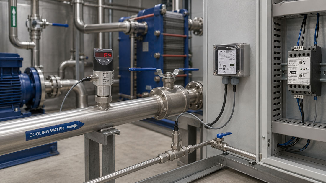
A flow switch should reliably detect whether a sufficient quantity of medium is flowing in a cooling, lubrication or process circuit. In practice, however, sporadic shutdowns, fluctuating switching signals or a missing alarm frequently occur even though the actual flow rate is too low.
The cause is not necessarily the flow switch itself. Installation position, flow direction, pipe diameter, air bubbles, contamination, viscosity and temperature influence the behaviour of the complete measuring point. A switching point configured too close to the normal operating flow or unsuitable hysteresis can also cause the output to switch whenever minor process fluctuations occur.
For reliable monitoring, the sensor technology, installation conditions and shutdown logic must be considered together. The required minimum flow is not determined by the sensor, but is derived from the cooling requirement, pump protection or process requirement.
Suitable instruments can be found in the ICS category Flow Switches and Flow Monitors. Additional measuring systems are grouped under Flow Measurement Technology.
Table of Contents
- What does a flow switch monitor?
- Distinguishing between mechanical and electronic flow switches
- Correctly assigning typical fault patterns
- Checking the installation position and flow direction
- Correctly defining the minimum flow
- Configuring the switching point and hysteresis
- Accounting for straight pipe runs and the flow profile
- Avoiding air bubbles and incompletely filled pipes
- Detecting contamination and deposits
- Accounting for viscosity and temperature
- Correctly configuring the switching output and controller
- Using a flow switch for dry-running protection
- Correctly performing a functional test
- Systematic diagnostic procedure
- Practical example: Sporadic cooling-water alarm
- Typical flow-switch errors
- What should be included in the documentation?
- Which products and solutions are suitable?
- Conclusion
- Frequently asked questions
What does a flow switch monitor?
A flow switch monitors whether a liquid or gas exceeds or falls below a defined limit. Unlike a precision flow meter, the primary objective is not necessarily an exact measured value, but a reliable switching signal.
Typical applications include:
- monitoring cooling-water circuits,
- dry-running protection for pumps,
- monitoring lubricating-oil circuits,
- monitoring cooling lubricants,
- enabling machines and heating systems,
- monitoring ventilation and extraction systems,
- monitoring filters and heat exchangers,
- detecting interrupted process flows.
A reliable switching point requires a representative and sufficiently stable flow condition at the measuring point. If the flow fluctuates more strongly at the sensor than in the rest of the pipe, even a technically faultless flow switch may operate unreliably.
Distinguishing between mechanical and electronic flow switches
| Measuring principle | Operating principle | Typical strengths | Typical influencing variables |
|---|---|---|---|
| Paddle or vane switch | The flow moves a paddle against a spring and actuates a microswitch | Simple, robust and without electronic evaluation | Installation position, pipe diameter, paddle length, viscosity and contamination |
| Calorimetric flow switch | Evaluates heat dissipation from a heated sensor tip | No moving parts and suitable for low flow velocities | Medium, temperature, deposits, air bubbles and insertion depth |
| Electronic flow switch with display | Measures a relative or absolute flow value and compares it with programmed limits | Configurable switching points, hysteresis, diagnostics and, in some cases, an analogue output | Measuring principle, installation, pipe geometry, parameter settings and teach status |
| Differential-pressure-based monitoring | Evaluates the pressure loss across a restrictor, filter or defined flow element | Also suitable for difficult-to-access pipes | Contamination, density, viscosity and changing system resistance |
The different measuring principles must not be interchanged without adaptation. A mechanical paddle switch responds to the force of the flow, while a calorimetric sensor evaluates heat transfer to the medium.
Two instruments may therefore have different switching points at the same volumetric flow rate, particularly if the medium, temperature, viscosity or pipe diameter changes.
Correctly assigning typical fault patterns
| Fault pattern | Probable causes |
|---|---|
| Switching signal fluctuates during operation | Switching point too close to the normal flow, insufficient hysteresis, air bubbles or a pulsating pump |
| Flow switch operates reliably only when the medium is cold | Temperature or viscosity influence; thermal sensor not configured under operating conditions |
| Alarm occurs after a filter replacement | Changed flow profile, air in the system or incorrect valve position |
| Alarm occurs only at high pump speed | Turbulence, cavitation, vibrating paddle or electrical interference |
| No alarm when the flow is interrupted | Switching point too low, blocked paddle, incorrect output logic or sensor located in a bypass flow |
| Display is stable, but the controller still reports a fault | Incorrect PNP or NPN wiring, contact bounce, input filter or cable fault |
| Switching point changes gradually | Deposits, filter contamination, changed medium properties or mechanical wear |
Before reconfiguring the instrument, it must be established whether the actual flow has changed or only the sensor signal has become unstable. An independent flow measurement is frequently required for this purpose.
Checking the installation position and flow direction
The permissible installation position depends on the design and manufacturer. Gravity influences the restoring force and therefore the switching point, particularly with mechanical paddle switches.
The following must generally be checked:
- Does the flow direction correspond to the arrow on the housing?
- Does the installation position comply with the operating instructions?
- Does the sensing element extend sufficiently far into the flow?
- Does the paddle avoid contact with both the pipe wall and pipe bottom?
- Is the sensing element secured against rotation?
- Does the pipe remain completely filled during operation?
- Can air or gas accumulate around the sensor?
A paddle must be able to move freely in the direction of flow. A paddle that is too long or installed at an angle may contact the pipe wall and consequently return slowly, incompletely or not at all.
With calorimetric insertion sensors, the active sensor tip must be fully surrounded by the medium. A position directly next to the pipe wall may produce an excessively low flow value because the velocity is lower in this area.
The sensor should not be used mechanically as a support for pipes or cables. Tensile forces, vibration and a rotated compression fitting can change the insertion depth or alignment.
Correctly defining the minimum flow
The required minimum flow is determined by the system being protected. The decisive factor is, for example, the flow rate required to cool a motor, laser, tool or heat exchanger sufficiently.
The smallest value measurable by the sensor is not automatically the appropriate switching point. A distinction must be made between:
- the lowest flow detectable by the sensor,
- the normal operating flow,
- the minimum permissible process flow,
- the switching point of the flow switch,
- the reset point resulting from the hysteresis.
For sensors specified in terms of flow velocity, the internal pipe diameter must be considered. For a uniform flow, the following simplified equation applies:
Q = v × A
For a circular pipe:
Q = v × π × Di² / 4
Where:
- Q: volumetric flow rate,
- v: average flow velocity,
- Di: actual internal pipe diameter.
With an internal diameter of 25 mm and a flow velocity of 0.5 m/s, the approximate volumetric flow rate is 0.88 m³/h.
The actual switching point should be sufficiently separated from normal fluctuations. At the same time, it must remain above the flow rate at which unacceptable heating or dry running may already occur.
Configuring the switching point and hysteresis
Hysteresis is the difference between the switching and reset points. It prevents the output from switching repeatedly in response to minor fluctuations.
Example of minimum-flow monitoring:
- Enable point with increasing flow: 12 l/min,
- shutdown point with decreasing flow: 10 l/min,
- hysteresis: 2 l/min.
The exact assignment of the switch-on and switch-off points depends on the selected output logic.
Insufficient hysteresis causes:
- chattering relays,
- frequent machine shutdowns,
- increased contact wear,
- unstable PLC signals.
Excessive hysteresis, by contrast, may cause the system to be re-enabled only after an unnecessarily high flow rate has been restored.
With electronic flow switches, a short switch-on or switch-off delay should also be considered in addition to the hysteresis. It can bridge individual pump pulses or air bubbles. However, a delay must not conceal an actual hazardous flow interruption for an unacceptably long period.
Accounting for straight pipe runs and the flow profile
Directly downstream of bends, valves, pumps, reducers and T-pieces, the flow is frequently asymmetrical or highly turbulent. A locally measuring flow switch may detect a different condition there from that prevailing across the rest of the pipe cross-section.
Particularly critical installation points include:
- immediately downstream of a 90-degree bend,
- directly downstream of a pump,
- at the outlet of a control valve,
- directly downstream of a significant reducer,
- at a branch or merging point,
- at a point affected by a pulsating piston pump.
Where possible, the sensor should be installed in a straight and completely filled pipe section. The required upstream and downstream straight lengths must be taken from the data sheet for the specific instrument.
If sufficient straight pipe lengths are unavailable, the function must be tested practically under all relevant operating conditions. Configuring the instrument only under constant workshop-flow conditions is then insufficient.
Avoiding air bubbles and incompletely filled pipes
Air bubbles are among the most frequent causes of sporadic false switching in liquid circuits.
With a calorimetric sensor, a passing gas bubble significantly changes heat dissipation. The sensor may briefly detect a considerably lower or higher flow condition.
With mechanical paddle switches, large air bubbles, pressure surges or changing liquid levels can cause the paddle to oscillate.
Suitable measures include:
- do not position the measuring point at the highest point of the pipe,
- completely vent the system after maintenance work,
- check the pump suction side for leaks,
- avoid cavitation,
- connect expansion and degassing vessels correctly,
- install the sensor in a permanently filled pipe section.
An electronic time delay must not be used as a substitute for eliminating continuous air ingress.
Detecting contamination and deposits
Deposits affect both mechanical and thermal flow switches.
On a paddle switch, particles or fibrous contamination can:
- block the paddle,
- delay its return movement,
- increase the effective surface area,
- permanently shift the switching point.
On a calorimetric sensor, a coating acts as thermal insulation. This changes the heat transfer between the sensor and medium. Oil films, limescale, cooling-lubricant residues or biological deposits can significantly affect sensitivity.
Cleaning may only be performed using approved agents and procedures. Aggressive brushes, abrasive materials or unsuitable solvents can damage the sensor surface, seals and coatings.
After cleaning, filter replacement or sensor replacement, the switching point must be tested again under actual operating conditions.
Accounting for viscosity and temperature
The viscosity of a medium affects the pressure loss, flow profile and force acting on a mechanical paddle. With oil, the viscosity may change considerably between a cold system start and warm continuous operation.
As a result, a flow switch may:
- switch too early with cold oil,
- have a different reset point with warm oil,
- switch repeatedly during the warm-up phase.
With calorimetric sensors, the thermal conductivity, heat capacity, density and temperature of the medium influence the measured heat dissipation.
A switching point configured for water must therefore not be transferred to water-glycol mixtures, oil or cooling lubricants without verification.
Where possible, the instrument should be configured using the actual medium at a representative operating temperature. If the composition of a water-glycol mixture changes, another functional test may be required.
Correctly configuring the switching output and controller
In addition to the process side, the electrical evaluation must also be checked.
Typical output types include:
- potential-free changeover contact,
- PNP switching output,
- NPN switching output,
- push-pull output,
- analogue output with an additional switching signal,
- IO-Link.
The following must be checked:
- supply voltage and polarity,
- pin assignment,
- PNP or NPN compatibility of the PLC input,
- normally open or normally closed function,
- maximum contact load,
- input filters and software delays,
- behaviour in the event of cable breakage or loss of supply voltage.
For protective functions, fail-safe logic is frequently appropriate so that insufficient flow, cable breakage or loss of supply voltage causes a shutdown. However, the specific implementation must correspond to the machine risk assessment and control architecture.
A small sensor contact should not directly switch a large contactor or solenoid-valve coil unless the permissible switching capacity is clearly sufficient. Interposing relays and suitable protective circuits may be required.
Using a flow switch for dry-running protection
A flow switch can shut down a pump if sufficient flow is not established after start-up or if the flow decreases during operation.
Effective dry-running protection must account for at least:
- the required pump start-up time,
- the pipe filling time,
- the minimum permissible pump flow,
- the sensor position in the circuit,
- reverse flow after the pump is switched off,
- behaviour when a valve is closed,
- the maximum permissible shutdown delay.
A time-limited start-up bypass may be required immediately after the pump starts. It must be only as long as necessary to establish the flow safely.
A flow switch does not automatically replace a complete pump-protection system. Depending on the application, additional pressure, level, temperature or motor-current monitoring may be required.
Correctly performing a functional test
A functional test must not be performed only by actuating a relay or simulating the PLC input. Such a test does not check the actual sensor response.
Suitable test procedure:
- Place the system in a safe test condition.
- Document the normal operating flow and medium temperature.
- Reduce the flow in a controlled manner using a suitable valve.
- Measure the actual flow using a reference instrument.
- Document the shutdown point of the flow switch.
- Then slowly increase the flow.
- Record the reset point and hysteresis.
- Test the alarm, machine shutdown and message text.
- Repeat the test under relevant operating conditions.
For electronic instruments, the display, analogue output, switching outputs, diagnostic messages and stored parameters must also be checked.
The flow switch should not be tested by turning the adjustment control until an apparently suitable condition is reached. This changes the original switching point and does not evaluate the actual process function.
Systematic diagnostic procedure
- Record when the fault occurs: Document whether it occurs during start-up, warming, load changes or continuous operation.
- Measure the actual flow: Use an independent flow meter or a defined volumetric collection method.
- Check the medium: Record the temperature, viscosity, concentration and possible air content.
- Check the installation: Verify the flow direction, installation position, insertion depth and pipe filling.
- Assess the measuring point: Check the distance from bends, valves, pumps and branches.
- Inspect the sensor: Check the paddle, sensor tip and filter for deposits or damage.
- Record the switching point: Determine the shutdown and reset values while changing the flow slowly.
- Check the hysteresis: Compare the difference between the two switching points with the process fluctuations.
- Check the electrical system: Verify the output type, supply, contact function and PLC input.
- Check the pump condition: Rule out cavitation, pulsating operation and fluctuating speed.
- Adjust the parameters: Make changes individually and then repeat the measurement.
- Perform a final test: Check the complete shutdown and restart chain.
Practical example: Sporadic cooling-water alarm
A machine tool is cooled by a closed water circuit. The normal flow rate is approximately 16 l/min. An electronic flow switch shuts the machine down sporadically even though the pump continues to operate.
The inspection identifies the following:
- The shutdown point is configured as 14.5 l/min.
- The actual flow fluctuates between 14 and 17 l/min.
- The sensor is positioned directly downstream of a 90-degree bend.
- Air remains in the circuit following maintenance work.
- The configured hysteresis is only 0.3 l/min.
The sensor is moved to a straight, permanently filled pipe section. The circuit is completely vented and the pump capacity is checked.
The thermal design specifies a minimum permissible cooling-water flow of 11 l/min. Accounting for the normal process fluctuations, the following values are defined:
- shutdown with decreasing flow: 12 l/min,
- restart enable with increasing flow: 14 l/min.
The functional test confirms that both switching points are reproducible. The sporadic shutdowns no longer occur, while an actual loss of flow continues to be detected reliably.
Typical flow-switch errors
| Error | Possible consequence | Suitable corrective action |
|---|---|---|
| Switching point configured directly at the normal operating value | Frequent false switching during minor fluctuations | Provide sufficient separation and suitable hysteresis |
| Sensor installed directly downstream of a pipe bend | Turbulent and asymmetrical flow signal | Select a straight, representative pipe section |
| Paddle contacts the pipe wall | Blocked or delayed switching movement | Correct the paddle length and alignment |
| Incorrect flow direction | Incorrect or missing switching action | Observe the direction arrow and installation instructions |
| Calorimetric sensor tip not fully surrounded by the flow | Excessively low or unstable reading | Check the insertion depth and pipe filling |
| Air bubbles in the cooling circuit | Brief false signals | Vent the system and eliminate the cause of air ingress |
| Deposits on the sensor | Shifted switching point and delayed response | Clean the sensor in accordance with the manufacturer’s instructions and retest it |
| Configured using water for subsequent operation with oil | Different switching point because of changed medium properties | Configure using the actual medium at operating temperature |
| PNP output connected to an unsuitable PLC input | Permanent or missing switching signal | Match the output and input electrically |
| Switch-on delay too long | Actual flow failure is detected too late | Limit the delay according to the permissible response time |
| Only the electrical output is simulated | The sensor and actual flow path are not tested | Perform the functional test by changing the flow in a controlled manner |
What should be included in the documentation?
Traceable test and configuration documentation should include at least:
- the system and measuring-point designation,
- the manufacturer, type and serial number of the flow switch,
- the measuring principle and output type,
- the medium and its composition,
- the medium temperature and operating pressure,
- the pipe material and internal pipe diameter,
- the installation position and flow direction,
- the distance from bends, valves and pumps,
- the normal operating flow,
- the minimum permissible process flow,
- the measured shutdown point,
- the measured reset point,
- the hysteresis and time delay,
- the reference instrument used,
- the condition of the paddle, sensor tip and filter,
- the result of the alarm and shutdown test,
- the modifications performed and final test.
Photographs of the installation position and a diagram of the pipework significantly simplify subsequent repeat tests.
Which products and solutions are suitable?
WIKA FSD-4 electronic flow switch
The WIKA FSD-4 monitors liquid media using the calorimetric measuring principle and contains no mechanically moving sensor components.
Depending on the configuration, up to two switching points and an analogue output are available. The instrument is configured using the buttons on the device or optionally via IO-Link.
The teach function allows the sensor to be adapted to the actual conditions at the measuring point. This is particularly useful when the pipe diameter, medium and flow profile differ from the reference conditions.
KSW compact electronic flow monitor
The KSW is a compact electronic flow monitor for liquid media.
The adjustable flow-velocity range extends from 0.05 to 3 m/s. The instrument has an SPDT switching output and is designed for operating pressures up to 20 bar.
The KSW is suitable for compact cooling and machine circuits, provided that the medium, temperature, insertion depth and installation conditions comply with the technical specifications.
SWW electronic flow-monitoring system with evaluation unit
The SWW system consists of a flow sensor and a separate evaluation unit.
Depending on the sensor and evaluation unit, ranges from low flow velocities up to 20 m/s are available. The sensitivity can be adjusted using coarse and fine settings.
The sensor tip must be fully surrounded by the medium. The system is therefore particularly suitable for applications in which the sensor and evaluation unit must be installed separately.
S6065 mechanical paddle flow switch
The S6065 operates with a mechanical paddle and an SPDT microswitch.
Depending on the pipe diameter and paddle version, the series covers flow ranges from approximately 0.6 to 165 m³/h. It is suitable for water, oil, cooling systems and lubrication systems.
The nominal pipe size, paddle length, installation position and free movement of the paddle must be considered during selection.
SWL electronic airflow monitor
The SWL is designed for monitoring airflow in ventilation and air-conditioning systems.
In combination with the associated evaluation unit, air velocities from approximately 0.1 to 20 m/s can be monitored. The sensor and evaluation unit have a separate design.
ICS Schneider Messtechnik provides support in selecting the measuring principle, switching range, installation position, process connection and output signal, as well as in designing cooling, pump and machine-monitoring systems.
Conclusion
An unreliably operating flow switch is not automatically defective. The problem is frequently caused by an unsuitable measuring point, a fluctuating process or inappropriate parameter settings.
Mechanical paddle switches respond to the force of the flow and installation position. Electronic calorimetric sensors are additionally influenced by the medium, temperature, deposits and air bubbles.
The switching point must be derived from the minimum permissible process flow. The lower measuring limit of the sensor alone is not a sufficient selection criterion.
Suitable hysteresis prevents fluctuating switching signals. Time delays can bridge brief interference, but must not conceal an actual loss of flow for a dangerously long period.
The sensor should be installed in a straight, permanently filled and representative pipe section. Air accumulation, severe turbulence and immediate proximity to pumps or control valves should be avoided.
The most reliable functional test is performed by changing the actual flow in a controlled manner. The shutdown point, reset point, hysteresis and complete response of the machine controller are documented during the test.
Frequently asked questions about unreliable flow switches
Why does the flow switch continuously switch on and off?
The switching point is frequently too close to the normal operating flow or the hysteresis is too small. Air bubbles, pump pulsations and turbulence can also cause the signal to fluctuate.
How is the correct minimum flow determined?
It is derived from the process requirement, such as the required cooling flow or minimum permissible pump flow. The switching point is then defined with a suitable safety margin.
Is the lowest measurable value of the sensor the appropriate switching point?
No. The sensor’s technical detection limit does not indicate which flow rate is still safe for the system.
Why does the installation position affect a paddle switch?
Gravity, spring force and the free movement of the paddle affect the switching point. Only installation positions approved by the manufacturer may therefore be used.
Why does a thermal flow switch respond to air bubbles?
Gas and liquid dissipate heat differently. An air bubble can therefore cause a significantly changed sensor signal for a short period.
Can the same switching point be used for water and oil?
Not without verification. Viscosity, density and thermal properties differ and can significantly change the switching behaviour.
How is the hysteresis tested?
The flow is slowly reduced until the output switches off. It is then increased until the output switches on again. The difference is the effective hysteresis.
Can a time delay prevent false switching?
It can bridge brief pulses or individual air bubbles. However, an excessively long delay may detect an actual flow failure too late.
Is simulating the PLC input sufficient as a functional test?
No. This does not test the sensor, installation conditions or actual flow path. The flow must be changed in a controlled manner and the complete signal chain must be tested.
When must the flow switch be replaced?
It must be replaced if the paddle or sensing element is damaged, the switching point is no longer reproducible or the instrument continues to operate outside the manufacturer’s specifications after cleaning and correct configuration.