


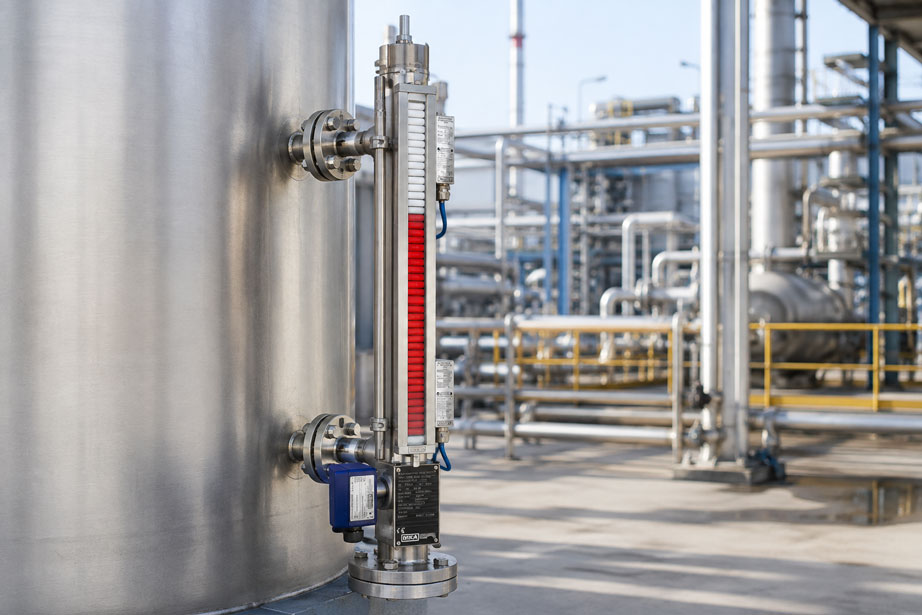
A bypass level indicator is ordered to match the vessel, installed and commissioned – yet the indication starts significantly above the bottom of the tank or does not reach the expected maximum level. In another case, the float continuously indicates a position several centimeters away from the actual liquid level. Such deviations are often not caused by a defective indicator, but by an incomplete or incorrect design of the measuring point.
For a bypass level indicator, the vessel geometry, connection positions and process conditions must already be known before manufacturing. Particularly important are the center-to-center dimension of the process connections, the required visible measuring range, the liquid density at operating temperature, process pressure and temperature, as well as materials and connection design.
The float is also not a universal component. Its buoyancy depends directly on the density of the medium. If the liquid density at high process temperature decreases significantly compared with the datasheet value at room temperature, the same float will immerse more deeply. In an unfavorable case, the position of the magnetic system may no longer correspond to the intended indication or the float may no longer have sufficient buoyancy reserve.
There are also design-related dead zones above and below the process connections. Therefore, connection spacing, overall length of the bypass chamber and the actually usable indication range are not automatically identical.
Suitable instruments can be found at ICS Schneider under WIKA KSR Kuebler level measurement technology. An overview of further measuring principles and instruments can be found under level measurement technology.
Table of Contents
- How does a bypass level indicator work?
- Why is the center-to-center dimension so important?
- Distinguishing between connection spacing, indication range and overall length
- Why upper and lower dead zones occur
- Why liquid density determines the float design
- Always consider density at the actual process temperature
- Pressure and temperature when selecting the float
- Special considerations for interface measurement
- Defining upper and lower process connections correctly
- Planning venting and draining
- Influence of viscosity and contamination
- Materials and chemical resistance
- How the float and magnetic indicator work together
- Adding transmitters and magnetic switches
- Insulation and temperature differences between tank and bypass
- Vertical installation and stress-free connections
- Typical fault patterns
- Which data are required for correct design?
- Systematic troubleshooting for incorrect indication
- Practical example: indication no longer correct after vessel modification
- Suitable WIKA KSR Kuebler products
- Conclusion
- FAQ
How does a bypass level indicator work?
A bypass level indicator essentially consists of a bypass chamber mounted on the side of the vessel. It is connected to the vessel via at least one lower and one upper process connection.
The vessel and bypass therefore form a connected liquid system according to the principle of communicating vessels. Under suitable conditions, a liquid level is established in the bypass that corresponds to the level in the vessel.
A float is located inside the bypass chamber. It contains a permanent magnetic system and follows the liquid level.
The magnetic field acts through the wall of the bypass chamber on an externally mounted magnetic indicator. This allows the level to be displayed visibly without the indicator itself coming into contact with the process medium.
The principle offers several practical advantages:
- direct local indication of the level,
- indication possible without electrical power,
- magnetic indicator separated from the process medium,
- optional addition of a transmitter,
- optional limit monitoring using magnetic switches.
For the principle to function reliably, however, the complete measuring chamber must be matched to the vessel and the medium.
Why is the center-to-center dimension so important?
One of the most important specifications when ordering a bypass level indicator is the so-called center-to-center dimension.
This generally refers to the vertical distance between the centerline of the lower process connection and the centerline of the upper process connection.
This dimension should be taken directly from the actual vessel design or an approved drawing.
The following request, for example, is problematic:
“Vessel height 2,000 mm, please supply a 2,000 mm long bypass indicator.”
The vessel height alone provides no information about the actual elevations of the two connection nozzles.
A vessel may, for example:
- have a curved bottom,
- have a dished head,
- have a curved top cover,
- stand on a base,
- have process connections positioned significantly above or below the required measuring range.
For manufacturing the bypass indicator, the overall vessel height is therefore not the decisive parameter, but rather the actual geometric position of the process connections.
Distinguishing between connection spacing, indication range and overall length
Three dimensions are frequently confused when specifying bypass indicators:
| Term | Meaning |
|---|---|
| Center-to-center dimension | Vertical distance between the centerlines of the upper and lower process connections |
| Indication range | Range over which the float or magnetic indicator can actually display the liquid level |
| Overall length | Total mechanical height of the bypass chamber including upper and lower extensions or closures |
These three dimensions are normally not identical.
The bypass chamber requires structural space below and above the actual connection area for:
- the float,
- float stops,
- the lower chamber closure,
- drain fittings,
- the upper closure or vent.
The required measuring range must therefore not simply be equated with the mechanical overall length.
For an inquiry, the dimensions should ideally be specified clearly, for example:
“Lower connection center = 0 mm, upper connection center = 1,500 mm, required visible level range from … to …”
Even better is a vessel drawing with clearly defined reference elevations.
Why upper and lower dead zones occur
The float has a real mechanical length. Its magnetic system is located at a defined position within the float.
The float therefore cannot travel arbitrarily close to the lower or upper end of the bypass chamber.
This creates design-related areas that must often be considered as dead zones or areas that cannot be fully measured.
At the lower end, for example, the float requires sufficient space so that it does not contact valves or the chamber closure when the vessel is empty.
Sufficient mechanical clearance is also required at the upper end.
For plant design, this means:
If the operator genuinely needs to see the range from 0 to 100% of the vessel, the process connections and bypass chamber must be designed so that the float movement can technically cover this range.
A connection positioned directly at the required 0% point therefore does not automatically mean that the magnetic indication can start exactly at this position.
The required upper and lower extensions depend on the specific instrument and float design and should therefore not be defined using a general rule.
Why liquid density determines the float design
The float follows the liquid level due to Archimedean buoyancy.
The buoyant force can be expressed in simplified form as:
FA = ρ · g · Vdisplaced
Where:
- FA = buoyant force,
- ρ = density of the liquid,
- g = gravitational acceleration,
- Vdisplaced = volume of liquid displaced by the float.
In a stable floating condition, the buoyant force approximately equals the weight of the float.
If the liquid density decreases, the float must therefore displace a larger volume and consequently immerses more deeply.
At a higher liquid density, it immerses less deeply.
This has two consequences:
- The float must provide sufficient buoyancy for the minimum density of the medium.
- The position of the magnetic system relative to the actual liquid surface depends on the float design.
The statement “float for water” is therefore not sufficient if, for example, a hydrocarbon with a significantly lower density is later to be measured.
Always consider density at the actual process temperature
A particularly common design error is to use the density from a safety data sheet or material datasheet at room temperature even though the process operates at a significantly higher temperature.
The density of many liquids decreases as temperature increases.
Example:
A medium has a density of 820 kg/m³ at 20 °C. However, the vessel operates continuously at 160 °C. For the float design, the value of 820 kg/m³ is not automatically decisive; instead, the actual or minimum density under the relevant operating conditions must be considered.
For changing operating conditions, the following should therefore be considered:
- minimum process temperature,
- normal operating temperature,
- maximum process temperature,
- associated minimum and maximum densities.
For float selection, the condition with the lowest expected liquid density is particularly critical.
If the density values are unknown, they should not be estimated. Reliable fluid property data for the actual process conditions should be used instead.
Pressure and temperature when selecting the float
In addition to density, pressure and temperature also influence the selection of the float.
A float is a closed mechanical component operated at process pressure. Its wall must therefore be suitable for the respective pressure and temperature load.
A float designed for an atmospheric water tank is not automatically suitable for a high-pressure application.
At minimum, the following information must therefore be known for the design:
- minimum operating pressure,
- normal operating pressure,
- maximum permissible operating pressure,
- minimum temperature,
- normal operating temperature,
- maximum temperature,
- density at the relevant temperatures.
Vacuum operation should also be explicitly specified.
Float selection must therefore always consider:
density + pressure + temperature + chemical resistance.
Special considerations for interface measurement
Suitable bypass systems can also be used to indicate an interface between two liquids.
However, this is a different design task from simple level measurement.
At minimum, the following must be known:
- density of the upper liquid,
- density of the lower liquid,
- densities at process temperature,
- temperature range,
- process pressure,
- chemical properties of both media.
The float must be designed so that it positions itself stably at the required interface.
A standard level float should therefore not be used for interface measurement without checking its suitability.
Emulsions or poorly defined transition layers can also limit the usefulness of such a measurement.
Defining upper and lower process connections correctly
The bypass indicator requires a hydraulic connection to the vessel.
Typical process connections include:
- flange connections,
- threaded connections,
- welded nozzles.
The choice of connection depends, among other things, on:
- process pressure,
- temperature,
- medium,
- piping standard,
- vessel design,
- maintenance requirements.
The lower connection
The liquid medium enters the bypass chamber from the vessel through the lower connection.
The connection should be positioned and sized so that reliable pressure and liquid equalization can take place.
With viscous, contaminated or solids-containing media, a very small connection can significantly increase the response time of the indication or become clogged.
The upper connection
In a closed vessel, the upper connection provides pressure equalization between the vessel gas space and the bypass chamber.
If this connection is blocked or accidentally isolated, a different gas pressure can build up or become trapped inside the bypass chamber.
The principle of communicating vessels will then no longer function under the intended conditions.
For troubleshooting, both process connections should therefore always be checked.
Planning venting and draining
Venting and draining facilities are very useful for commissioning and maintenance and may be required depending on the application.
Upper vent
A vent at the upper end can, for example, be used to remove trapped gases in a controlled manner during commissioning.
Lower drain
A lower drain can be useful for:
- completely draining the bypass chamber,
- flushing,
- removing deposits,
- maintenance work.
For hot, toxic, flammable or pressurized media, venting and draining must of course be designed in accordance with the plant and safety requirements.
For media that tend to cause contamination, consideration should already be given during the design stage to how the bypass chamber will later be cleaned.
Influence of viscosity and contamination
The operating principle of a bypass indicator requires the liquid level in the bypass chamber to equalize sufficiently quickly with the vessel level and the float to remain freely movable.
With highly viscous media, this equalization can be considerably slower.
Other problematic media can include:
- sticky products,
- resins,
- crystallizing products,
- sludges,
- solid particles,
- polymerizing media,
- product deposits.
A sticking float can cause the indication to remain stationary after a level change and then suddenly jump to the new position.
A restricted or clogged process connection, on the other hand, can cause the liquid level in the bypass chamber to adjust only slowly.
For problematic media, connection cross-sections, chamber diameter, cleaning options and, where appropriate, alternative measuring principles should therefore be evaluated at an early stage.
Materials and chemical resistance
All wetted components must be suitable for the process medium.
These include in particular:
- bypass chamber,
- float,
- process connections,
- seals,
- valves and fittings.
The selection should not be based solely on the normal process medium. Where applicable, the following should also be considered:
- cleaning media,
- flushing chemicals,
- temperature peaks,
- start-up and shutdown conditions,
- possible contaminants.
A material that is chemically suitable at room temperature does not automatically have the same resistance at elevated temperature.
For corrosive media, a reliable material compatibility assessment should therefore form part of the measuring-point design.
How the float and magnetic indicator work together
The float contains a permanent magnetic system. As the float rises and falls, this magnetic field moves along the bypass chamber.
The externally mounted magnetic indicator is actuated without contact.
The indication therefore requires no mechanical penetration through the pressure boundary of the bypass chamber.
If the indication appears to “stick” at one position, several causes are possible:
- the float itself is not moving freely,
- the magnetic indicator has been mechanically damaged,
- the indicator elements have been affected by a strong external magnetic field,
- the float was installed upside down if the design requires a defined orientation,
- the magnetic indicator and float design do not match.
During maintenance, the external indication should therefore not be the only component inspected. The first question is whether the float inside the chamber is actually moving in accordance with the liquid level.
Adding transmitters and magnetic switches
A purely magnetic indication provides direct local information. In many applications, however, the level must additionally be processed by a PLC or control system.
Depending on the design, bypass level indicators can therefore be supplemented with external measuring transducers or level transmitters.
The advantage is that the same float can simultaneously be used for:
- local visual indication,
- continuous electrical level measurement,
- limit signals
.
Magnetic switches
Externally mounted magnetic switches can, for example, perform the following functions:
- minimum alarm,
- maximum alarm,
- pump enable,
- overfill protection within the limits of the applicable measuring concept.
The mechanical position of a magnetic switch must be referenced to the actual magnetic position of the float.
After installation or adjustment of the switching position, the function should therefore be verified using an actual level change or the specified test procedure.
Insulation and temperature differences between tank and bypass
With hot or very cold media, another effect can occur: The bypass can have a significantly different temperature from the actual vessel.
This is not only relevant to viscosity. The density of the medium can also differ.
If the medium in the bypass cools significantly more than the medium inside the tank, its density in the bypass chamber may be higher than in the vessel.
For hydrostatic pressure, the simplified relationship is:
p = ρ · g · h
At the same pressure at the lower connection, different average liquid densities can therefore lead to different liquid heights.
In simplified form, with identical gas pressures:
ρTank · hTank ≈ ρBypass · hBypass
If the liquid in the bypass is significantly denser than in the vessel, the liquid level in the bypass can therefore be correspondingly lower.
This effect is particularly relevant with:
- very hot liquids,
- long bypass chambers,
- strongly temperature-dependent density,
- uninsulated bypass chambers on insulated vessels.
Depending on the application and process, suitable insulation or temperature management of the bypass system may therefore be useful.
However, insulation should always be appropriate for the specific design. The magnetic indicator, transmitter and switches must not be exposed to impermissible thermal loads or completely covered.
Vertical installation and stress-free connections
A float must be able to move freely up and down inside the bypass chamber.
The bypass chamber should therefore be installed and aligned in accordance with the manufacturer’s specifications.
A significantly inclined installation can cause the float to:
- contact the chamber wall more strongly,
- experience increased friction,
- stick more easily when contaminated media are present.
It is equally problematic to compensate for an incorrect connection spacing by mechanically forcing the bypass chamber into position.
The process connections should be aligned and the installation should be free of mechanical stress.
If the connection spacing on the vessel does not match the ordered center-to-center dimension, a structural correction is preferable to forcibly aligning the instrument.
Typical fault patterns in bypass level indicators
| Observation | Possible cause | Recommended check |
|---|---|---|
| Indication begins significantly above the required 0% point | Lower dead zone or incorrect connection position | Check lower connection dimension, float length and actual indication range |
| 100% tank level is not fully indicated | Upper connection or usable float travel is too low | Check center-to-center dimension and upper dead zone |
| Indication has a constant vertical offset | Float not designed for the actual liquid density | Compare density at operating temperature with the float design |
| Float sinks or remains at the bottom | Density too low, float damaged or filled with medium | Check float design, minimum density and mechanical condition |
| Indication responds with a significant delay | Viscous medium or restricted process connection | Check upper and lower connections for free passage |
| Indication suddenly jumps by several centimeters | Float sticks due to deposits and then releases | Clean or inspect bypass chamber and float |
| Indication is correct when cold but incorrect during hot operation | Density change or temperature difference between tank and bypass | Check process density and temperature distribution |
| No plausible indication after maintenance | Float missing, installed incorrectly or blocked | Check float and magnetic orientation according to the instrument design |
| Bypass indicates a different level from a sight glass or reference measurement | Blocked connection, trapped pressure or temperature/density difference | Check both process connections and temperature conditions |
| Level transmitter does not agree with the magnetic indicator | Incorrect scaling, mounting position or magnetic assignment | Check mechanical indication and electrical output signal separately |
Which data are required for correct design?
A bypass level indicator should ideally not be requested using only the information “2-meter-high vessel”.
The following information is useful for a reliable selection:
- Medium: clear identification and, where applicable, chemical composition.
- Density: particularly the minimum density under actual operating conditions.
- Temperature: minimum, normal operating temperature and maximum.
- Pressure: minimum or vacuum, operating pressure and maximum pressure.
- Viscosity: particularly for viscous media.
- Center-to-center dimension: distance between the lower and upper process connections.
- Required measuring range: actual 0% and 100% points.
- Process connections: flange, thread or welded connection including nominal size and pressure rating.
- Materials: requirements for chamber, float and seals.
- Venting and draining: required connections or valves.
- Local indication: magnetic indicator and, where required, scale.
- Electrical signal: if an additional level transmitter is required.
- Limit contacts: number and required switching points.
- Hazardous-area requirements: if the measuring point is located in a potentially explosive atmosphere.
- Insulation: if thermal insulation or a special version is required.
- Vessel drawing: preferably showing connection positions and reference elevations.
The more complete this information is, the lower the risk that a mechanically fitting bypass indicator will later prove unsuitable for the application from a measurement perspective.
Systematic troubleshooting for incorrect indication
If an existing bypass indicator shows an implausible level, the float should not be replaced immediately.
A useful test procedure is:
- Check the reference level: Is it certain that the assumed tank level is correct?
- Check the lower connection valve: Is the liquid path fully open?
- Check the upper connection valve: Can the gas pressure equalize correctly?
- Check lines and nozzles: Are there deposits or blockages?
- Check the center-to-center dimension: Does the actual installation correspond to the original design?
- Check the float: Correct type, freely movable and mechanically undamaged?
- Check density: Does the actual process density match the design density?
- Consider temperature: What is the actual density of the medium during operation?
- Compare tank and bypass temperatures: Are there significant temperature differences?
- Check the magnetic indicator: Does the indication correctly follow a manually or controllably moved float?
- Check the transmitter separately: If installed, compare the electrical signal and scaling with the mechanical indication.
- Only then replace components: Identify the cause systematically.
This procedure helps distinguish between an actual instrument fault and unsuitable design conditions or changed process conditions.
Practical example: indication no longer correct after vessel modification
In a chemical plant, a vessel is monitored using a bypass level indicator. The existing indicator operated reliably for several years.
As part of a plant modification, the vessel is replaced. The new tank has approximately the same volume and overall height. The existing bypass indicator is therefore reused.
After commissioning, however, the magnetic indicator already shows “empty” even though a significant quantity of liquid remains in the vessel. At the same time, the upper region of the tank is never fully reached on the indication.
Step 1: Check sensor function
The float and magnetic indicator are checked. Both operate mechanically without fault.
Step 2: Compare vessel drawings
The drawings show that the lower connection on the new vessel is positioned approximately 120 mm higher and the upper connection approximately 80 mm lower than on the old tank.
The actual center-to-center dimension and therefore the hydraulically measurable range have been significantly reduced.
Step 3: Consider dead zones
The float also requires mechanical travel space at both ends. The actually usable indication range is therefore even smaller than the pure connection spacing.
Step 4: Check process data again
The review additionally shows that the medium is now operated at a higher temperature than in the original design. The liquid density is therefore lower.
Step 5: New design
A new bypass indicator is therefore designed for the new vessel with the correct connection spacing, suitable upper and lower extensions and a float matched to the minimum operating density.
Result: The old bypass indicator was not defective. The vessel geometry and process conditions had changed, so the original design was no longer suitable.
The example demonstrates: A bypass level indicator is a measuring system designed specifically for the process and vessel and is not simply an interchangeable standard tube of the same length.
Suitable WIKA KSR Kuebler products for bypass level measurement
WIKA Type BNA – bypass level indicator with magnetic indication
The WIKA Type BNA is designed for continuous level indication on vessels.
The bypass chamber is connected to the side of the vessel through at least two process connections. A float with an integrated magnetic system follows the liquid level and transmits its position without contact to the externally mounted magnetic indicator.
The series is manufactured specifically for the process and application and allows different:
- process connections,
- materials,
- float designs,
- pressure and temperature ranges,
- magnetic indicators,
- optional level transmitters,
- optional magnetic switches.
Depending on the specific version, the product family offers applications from vacuum up to 400 bar, temperatures from -196 °C to +450 °C and liquid densities from 340 kg/m³.
These values should be regarded as limits of the product family. The specific version must be selected separately for the actual combination of pressure, temperature, density, medium and material.
Further information can be found under WIKA KSR Kuebler level indicators at ICS Schneider.
WIKA BFT – float for bypass level indicators
The WIKA Type BFT is a float for bypass level indicators. The integrated magnetic system transmits the float position without contact to externally mounted indicators, switches and measuring transducers.
Three physical quantities are particularly important for selection:
- pressure,
- temperature,
- density.
Chemical resistance to the medium must also be considered.
For this reason, when ordering a replacement float, it is not sufficient to specify only the outside diameter or length of the existing float. The original process data or the actual current operating conditions must also be known.
WIKA BMD – magnetic indicator for bypass level indicators
The WIKA BMD magnetic indicator visualizes the position of the magnetic float outside the bypass chamber.
The indicator operates without contact through the chamber wall and requires no electrical power for purely local level indication.
The indicator therefore remains separated from the process medium while the level remains directly visible at the vessel.
Which version is suitable for the application?
| Requirement | Important design parameter |
|---|---|
| Simple liquid level in a tank | Center-to-center dimension, medium, density, pressure and temperature |
| Low-density liquid | Select float specifically for the minimum operating density |
| Hot medium | Consider density at operating temperature and thermal conditions of the bypass |
| High-pressure vessel | Design chamber and float for maximum process pressure |
| Viscous or contaminating medium | Check connection cross-sections, float mobility and cleaning options |
| Continuous electrical signal required | Add a suitable level transmitter to the bypass indicator |
| Minimum/maximum limit values required | Add suitable magnetic switches |
| Interface between two liquids | Special interface design based on the densities of both liquids |
Further products can be found under WIKA KSR Kuebler level measurement technology at ICS Schneider.
Conclusion
A bypass level indicator must match both the vessel geometry and the physical process conditions.
The most important mechanical dimension is often the center-to-center dimension of the two process connections. However, this must not be confused with the overall length or the actual usable indication range. Float length and the design-related upper and lower dead zones must also be taken into account.
Equally important is the density of the medium under actual operating conditions. It determines how deeply the float immerses and whether sufficient buoyancy is available at all. Particularly with hot media, a density value specified at 20 °C must therefore not be used without verification.
Pressure and temperature also influence the mechanical design of the float. Materials must be compatible with the process medium and, where applicable, with cleaning media.
For viscous or contaminating liquids, sufficiently open process connections and good cleanability are important. With hot media, a temperature and therefore density difference between the vessel and bypass can additionally cause systematic deviations.
The most important rule when ordering is therefore: Do not specify only the required length of the bypass indicator. Consider the vessel drawing, connection spacing, actual measuring range, medium, density, pressure and temperature together.
The same principle applies to troubleshooting: First check the connection geometry, unrestricted process connections and process data – only then consider the float or magnetic indicator as the source of the error.
FAQ: Designing bypass level indicators
What is a bypass level indicator?
A bypass level indicator is a measuring chamber mounted on the side of a vessel and connected to it through process connections. A magnetic float follows the liquid level and actuates an externally mounted magnetic indicator without contact.
What does the center-to-center dimension mean for a bypass indicator?
The center-to-center dimension generally refers to the vertical distance between the centerline of the lower process connection and the centerline of the upper process connection. This dimension is particularly important for mechanically matching the instrument to the vessel.
Is the center-to-center dimension the same as the measuring range?
Not automatically. The float requires mechanical travel space above and below the process connections. Connection spacing, float geometry and the actual required indication range must therefore be considered together.
Is the overall length of the bypass chamber the same as the connection spacing?
No. The bypass chamber normally has additional sections above and below the connection centerlines. Overall length and center-to-center dimension are therefore different specifications.
Why does a bypass level indicator have dead zones?
The float has a physical length and cannot mechanically travel to the extreme ends of the chamber. Additional space is also required for stops, chamber closures, draining and, where applicable, venting.
Why must the liquid density be specified when ordering?
Density determines the buoyant force acting on the float. At lower density, the float immerses more deeply. If the density is too low for the selected design, the float may no longer operate as intended.
Which density must be specified?
The decisive value is the density under actual operating conditions. In particular, the lowest expected liquid density within the intended temperature and process range is usually relevant.
Why is the density at 20 °C not always sufficient?
Many liquids become less dense as temperature increases. If the vessel operates at 150 °C, for example, the actual operating density may be significantly lower than the table value at 20 °C.
What happens if the float was designed for a density that is too high?
If the actual liquid is significantly less dense than assumed during design, the float will immerse more deeply. Depending on the deviation, this can cause an indication offset or result in insufficient buoyancy reserve.
Does process pressure influence float selection?
Yes. The float is a closed component operating within the process pressure and must be mechanically designed for the intended pressure and temperature combination.
Why must vacuum also be specified?
If a vessel is operated under vacuum even temporarily, this forms part of the intended process range and must be considered when designing the chamber, float and connections.
Why does a bypass indicator require an upper process connection?
In a closed vessel, the upper connection ensures that the gas space of the bypass chamber is pressure-connected to the gas space of the vessel. This allows the liquid level to establish itself according to the principle of communicating vessels.
What happens if the upper connection is blocked?
A trapped or different gas pressure can then develop in the bypass chamber. The level in the bypass may no longer correctly follow the level in the vessel.
What happens if the lower connection is blocked?
Liquid exchange between the vessel and bypass is restricted or interrupted. The indication may therefore respond with a significant delay or remain at an old level.
Why does a bypass indicator respond slowly with viscous media?
At high viscosity, liquid equalization through the process connections takes longer and the movement of the float may also be more strongly damped. Connection cross-sections and chamber geometry must therefore be appropriate for the application.
Can a bypass indicator be used with sticky media?
This depends on the medium, viscosity, tendency to form deposits and available cleaning options. Highly sticky or crystallizing products can impair float movement or block process connections. Suitability should therefore be assessed specifically for the application.
Why are venting and draining useful?
They simplify commissioning, maintenance, complete draining and cleaning of the bypass chamber. The specific design must be suitable for the medium and the applicable pressure and safety requirements.
Can a bypass indicator also provide an electrical level signal?
Yes. Suitable versions can additionally be equipped with external level transmitters. This provides both local magnetic indication and a continuous electrical signal.
Can additional limit switches be installed?
Suitable versions can be equipped with magnetic switches mounted externally on the bypass. These can be used, for example, for minimum or maximum monitoring.
Why can a hot tank show a different level from the bypass?
If the medium in the bypass cools significantly more than the medium in the vessel, its density can change. Different average liquid densities can result in different liquid heights due to the hydrostatic relationship.
Should a bypass level indicator be insulated?
This depends on the process and instrument design. With very hot or very cold media, suitable insulation can help reduce large temperature differences between vessel and bypass. At the same time, the magnetic indicator, transmitter and switches must remain within their permissible temperature ranges.
Can an existing bypass indicator simply be reused on a new tank?
Only if the connection spacing, required measuring range, process connections, medium, density, pressure and temperature still correspond to the original design. A similar vessel height alone is not sufficient evidence of suitability.
Which information should I provide when requesting a bypass level indicator?
At minimum, the medium, density at operating temperature, pressure, temperature, center-to-center dimension, required measuring range, process connections and material requirements should be provided. A vessel drawing showing the actual connection positions is particularly helpful.
Which product is suitable for a conventional bypass level indication?
For such applications, the WIKA Type BNA from the WIKA KSR Kuebler level measurement portfolio is one suitable option. The instrument is designed specifically for the process and application based on the vessel, connections, float and operating conditions.