


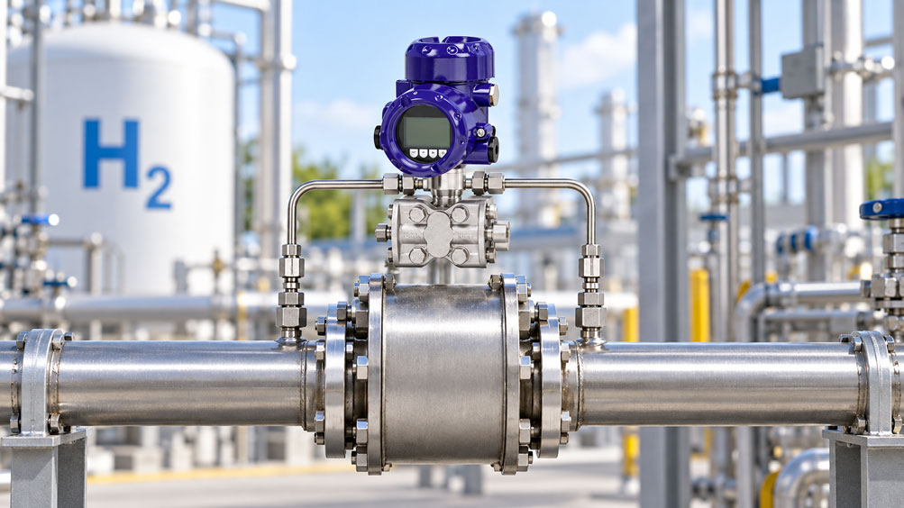
A hydrogen line is operating, for example, at a pressure of 200 bar. A filter is installed between the compressor, storage system or pressure regulation section and the downstream process. When clean, this filter causes a pressure drop of only around 40 to 80 mbar. As contamination increases, the differential pressure gradually rises and is intended to trigger a maintenance alarm at, for example, 250 mbar.
At first glance, the measuring task appears simple: measure the pressure upstream of the filter, measure the pressure downstream of the filter and subtract the two values. However, with a line pressure of 200 bar and a pressure drop of only a few hundred millibar, this method quickly becomes problematic.
The differential pressure of interest is extremely small compared with the absolute or static process pressure. A pressure drop of 100 mbar at a line pressure of 200 bar corresponds to only 0.05 percent of the superimposed pressure. Two conventional high-pressure transmitters would therefore have to measure two very large and almost identical values so accurately that their small difference could be determined reliably.
This is exactly what a differential pressure transmitter is designed for. It does not measure two large pressures independently and then calculate the difference mathematically. Instead, the high-pressure and low-pressure sides act on a common differential pressure measuring system. Both sides can be exposed to almost the same high static pressure while the measuring cell specifically detects the small difference between them.
This makes the measuring task significantly easier from a metrological perspective. At the same time, however, new requirements arise: the transmitter must safely withstand the high static line pressure. It must measure the small differential pressure with sufficient accuracy under these conditions. One-sided overload during start-up or due to an incorrect valve position must not damage the measuring system. In addition, all wetted materials, seals, impulse lines and valves must be suitable for hydrogen and the specific process conditions.
The most important rule is therefore: When measuring differential pressure across a hydrogen filter, measuring range and line pressure must not be confused. A measuring range of 0 … 250 mbar does not mean that the transmitter only needs to be suitable for 250 mbar process pressure. The decisive question is whether the measuring cell can safely, leak-tightly and accurately measure, for example, 0 … 250 mbar differential pressure while simultaneously exposed to 200 bar static pressure.
Why differential pressure is suitable for filter monitoring
A filter creates flow resistance. In order for the gas to pass through the filter medium, the pressure upstream of the filter must be slightly higher than the pressure downstream.
In simplified form, the differential pressure is:
Δp = pupstream of filter - pdownstream of filter
With a clean filter, this pressure drop is comparatively small. As the filter becomes increasingly loaded, the free flow cross-sections within the filter element become smaller. The resistance increases and a greater pressure difference is required to maintain the same gas flow.
This is exactly why differential pressure is highly suitable for monitoring the condition of a filter.
However, differential pressure must not be considered independently of flow. A filter that produces a pressure drop of 200 mbar at a high mass flow may show only 40 mbar at a considerably lower flow rate, even though its contamination level has not changed.
The measured differential pressure therefore initially describes the current hydraulic or flow resistance under the prevailing process conditions.
For meaningful filter diagnostics, differential pressure, flow, gas condition and, where relevant, temperature must be considered together.
This can be particularly important in hydrogen systems because test benches, electrolyzers, storage systems and fuel-cell systems are often operated over a wide load range.
Why two high-pressure transmitters are often not a good solution
Mathematically, differential pressure could also be calculated from two independent pressure measurements.
Assume that the pressure upstream of the filter is:
p1 = 200.120 bar
and downstream of the filter:
p2 = 200.000 bar
The required differential pressure is:
Δp = 0.120 bar = 120 mbar
For process control, each of the two high-pressure transmitters would have to measure so accurately that this small difference could be determined reliably from two values of approximately 200 bar.
An example illustrates the problem. If two pressure transmitters with a range of 0 … 250 bar and an accuracy of ±0.1 % of full scale are used, this specification alone corresponds to a possible deviation per sensor of:
250 bar × 0.1 % = 0.25 bar
That is 250 mbar per measuring point.
In our example, however, the required filter pressure drop is only 120 mbar.
Even if both sensors operate very stably under normal conditions, it is immediately apparent that calculating the difference between two large measuring ranges is unfavourable for a precise 120 mbar measurement.
A true differential pressure transmitter, by contrast, can be configured directly for a range such as 0 … 250 mbar even though a high static pressure is present simultaneously on both process sides.
This means that measurement resolution is used where it is actually required: for the small differential pressure rather than the large common line pressure.
Consistently distinguish differential pressure from static pressure
In differential pressure measurement, static pressure is also commonly referred to as common-mode pressure. Both sides of the transmitter are exposed to almost the same process pressure.
For a filter, for example:
H side = 200.12 bar
L side = 200.00 bar
Differential pressure = 0.12 bar
The differential pressure measuring cell therefore only needs to evaluate a measuring signal of 120 mbar. Mechanically, however, the complete process measuring system must simultaneously withstand approximately 200 bar.
For this reason, these two requirements are specified separately in data sheets.
A differential pressure transmitter can, for example, have a measuring range of only a few millibar while still being designed for 160 or 400 bar static pressure.
The static pressure limit must never be derived from the differential pressure range.
Conversely, a static pressure rating of 400 bar does not mean that a differential pressure of 400 bar between the H and L sides is permissible. The differential pressure measuring element has its own measuring and overload limits.
This distinction is fundamental in high-pressure hydrogen systems.
Influence of static pressure on measurement accuracy
Even if both sides are exposed to almost the same pressure, the high static pressure is not completely without metrological effect.
A real differential pressure sensor contains mechanical diaphragms, filling fluid, seals and an elastic measuring system. High common-mode pressure can therefore produce a small additional zero-point or span effect.
For a measuring task of, for example, 100 mbar, even a zero shift of only a few millibar can be relevant.
The static pressure effect is therefore just as important to device selection as the basic accuracy specification.
A transmitter with a basic accuracy of 0.075 % or 0.1 % may have additional specified effects under high static pressure. These specifications must be evaluated together for a reliable uncertainty assessment.
This is particularly important with high turndown. If a measuring cell with a considerably larger nominal range is scaled down to a very small differential pressure range, zero-point, temperature and static pressure effects can become more significant relative to the configured range.
The transmitter should therefore not merely be capable of “displaying 0 … 100 mbar somehow”. The underlying measuring cell should be sensibly matched to the actual differential pressure task.
Selecting the differential pressure range correctly
For filter monitoring, the measuring range should cover the complete operating condition of the filter while not being unnecessarily large.
Assume that a new filter produces a pressure drop of approximately 60 mbar at rated flow. The maintenance limit is 250 mbar and an abnormal process condition can briefly reach approximately 350 mbar.
A measuring range of 0 … 1 bar might technically be usable, but only a small portion of the signal would be used for the operating range of interest.
A range of, for example, 0 … 400 or 0 … 500 mbar may be considerably more appropriate for this task, provided the static pressure rating, overload limits and process conditions are suitable.
On the other hand, the range should not be selected so narrowly that even a short pressure spike moves the sensor outside its intended measuring range.
Normal pressure drop, warning threshold, maximum expected differential pressure and possible fault scenarios must therefore be considered together.
The flow dependence of the filter is also important. If the maximum process flow is increased significantly, the pressure drop of a clean filter will rise even without additional contamination.
An alarm limit should therefore not be defined solely on the basis of one operating point.
Consider one-sided overload as a critical operating condition
The normal operating condition of a differential pressure transmitter is comparatively comfortable: both sides are exposed to nearly the same high pressure and the difference is only a few millibar or a few hundred millibar.
During start-up, venting, purging or incorrect operation of a valve manifold, however, a completely different situation can briefly occur.
If the H side is already pressurized to 200 bar while the L side is still depressurized, the measuring cell no longer sees only 100 mbar differential pressure. For a short period, almost the entire 200 bar can act on the differential pressure system from one side.
This is a significantly more critical load case than normal filter operation.
For this reason, process differential pressure transmitters have defined one-sided overload limits and are often installed together with a valve manifold.
The correct valve sequence during start-up is therefore part of the safety concept of the measuring point.
A high static pressure rating does not automatically mean the same one-sided differential pressure overload capability. Both specifications must be considered separately in the data sheet.
Why a 3- or 5-valve manifold is important
A valve manifold mounted directly on the differential pressure transmitter not only makes maintenance easier. It also helps to apply process pressure to the sensitive differential pressure measuring cell in a controlled manner.
A conventional 3-valve manifold has an isolation valve on the high-pressure side, an isolation valve on the low-pressure side and an equalizing valve between the two sides.
The equalizing valve can connect the H and L sides. This means that almost the same pressure is present on both sides of the measuring cell and the differential pressure approaches zero.
This condition is particularly useful for zero-point checks and controlled start-up.
A 5-valve manifold typically adds further vent or test connections. This allows calibration and maintenance work to be carried out in a more structured manner.
With hydrogen, the manifold is also an important part of the leak-tightness chain. Material, seat design, packing, process connections and pressure rating must therefore be specified just as carefully as the transmitter itself.
The valve sequence should not be improvised. The manufacturer’s instructions and the operating procedure determine the sequence in which isolation and equalizing valves are operated.
Consider hydrogen-specific materials and leak tightness
Hydrogen places different demands on pressure measuring points than many conventional gases.
The molecule is very small and can permeate through sealing systems and materials more easily or escape through very small leakage paths. At the same time, hydrogen-induced material effects can become relevant with certain materials and loading conditions.
For this reason, the general statement “stainless-steel transmitter” is not sufficient for an H₂ measuring point.
All wetted components must be considered: process flanges, isolating diaphragms, valve manifold, tubing, fittings, valve seats and seals.
The specific stainless steel or nickel alloy used can also be relevant. Many process differential pressure transmitters are available with different wetted materials such as stainless steel, Hastelloy or Monel. The appropriate combination for the specific hydrogen application must be determined from pressure, temperature, purity requirements and manufacturer approval.
Elastomer seals require particular attention. FKM, NBR, EPDM, FFKM and other materials differ significantly in gas permeation, temperature range and chemical suitability.
With high-purity hydrogen, cleanliness of the measuring point is also important. Contamination from assembly, lubricants or unsuitable sealing materials may be undesirable depending on the process.
Hydrogen compatibility should therefore always be confirmed for the complete ordered device configuration and not derived solely from the product name.
Correctly design impulse lines for hydrogen
Impulse lines are often installed between the filter and the differential pressure transmitter. They transfer the pressure upstream and downstream of the filter to the two process connections of the transmitter.
With gases, these lines should be arranged so that no unwanted liquid pockets can form and both sides have comparable dynamic behaviour.
With hydrogen, the additional requirement is a permanently leak-tight connection.
Every additional fitting increases the number of potential leakage points. A compact design with sensible line lengths and as few connections as possible is therefore often advantageous.
The two impulse lines should also be designed as symmetrically as possible. Strongly differing line lengths and internal volumes can influence the dynamic behaviour of the two pressure sides differently.
With slowly increasing filter contamination, this is usually less critical than during rapid process changes. In pulsating or rapidly switching H₂ systems, however, asymmetric pressure transmission can generate additional transient differential pressure signals.
Temperature differences between the two impulse lines should also be minimized wherever possible. Although the medium is a gas, temperature and pressure still affect its density and therefore its condition within the lines.
Correctly assess temperature and density changes
The differential pressure across a filter does not depend solely on the degree of contamination.
Gas density, viscosity and flow also influence the pressure drop.
Hydrogen has a particularly low density. At a pressure of 200 bar, however, the gas state is completely different from that at atmospheric pressure. Temperature and real-gas properties additionally influence density.
For this reason, a filter characteristic should always be considered under the intended operating conditions.
A differential pressure of 150 mbar at high mass flow may indicate a completely clean filter, while the same value at a significantly lower flow rate could already indicate substantial loading.
For demanding systems, it is therefore sensible not to evaluate filter condition solely using a fixed Δp limit, but to include the current flow or mass flow.
A PLC can, for example, compare the measured differential pressure with a reference value expected for the current flow rate.
This makes it easier to separate the influence of changing load conditions from the actual increase in filter resistance.
Consider measurement dynamics and filter pulsations
In electrolyzer, compressor and test-bench systems, hydrogen pressure can be dynamic. Valves switch, compressors generate pulsations and pressure regulators respond to load changes.
The differential pressure transmitter sees these changes on both process sides.
With perfectly symmetrical pressure transmission, identical pressure changes would largely act as a common-mode signal and only the actual filter pressure drop would remain.
In practice, however, the H and L sides do not respond completely identically. Different impulse lines, damping elements or local process volumes can cause rapid pressure changes to reach the sensor with a slight time offset.
For a few milliseconds, a large apparent differential pressure can then occur even though the steady-state filter pressure drop is much smaller.
Electronic damping can reduce such peaks in the output signal. However, it does not change the actual mechanical load case of the sensor.
Two questions must therefore be answered separately during design: how quickly should the measured filter condition be displayed, and what actual transient pressure difference can occur at the measuring cell?
Check zero point at high static pressure
A particularly useful test for a differential pressure measuring point is a zero-point check while the static process pressure is applied.
Using the specified valve procedure, both sides of the differential pressure transmitter are brought to the same pressure.
Ideally:
pH = pL
and therefore:
Δp = 0
If the transmitter still indicates a relevant differential pressure at, for example, 200 bar common-mode pressure, it must be determined whether the cause is a static pressure effect, zero shift, valve problem or an actual remaining pressure difference between the two sides.
A zero-point check at atmospheric pressure alone does not completely represent this operating condition.
Especially with small differential pressure ranges, it is therefore important to know how stable the zero point remains under actual line pressure.
The ability to perform a zero adjustment does not replace technical assessment. A suddenly and significantly changed zero point should not simply be repeatedly compensated by configuration without investigating the cause.
From differential pressure to actual filter condition
An increasing differential pressure is a very good indication of increasing filter resistance. Nevertheless, a direct percentage value for “filter contamination” should not automatically be derived from it.
The filter element has a characteristic pressure-drop curve as a function of gas flow, gas condition and loading.
The manufacturer’s filter characteristic is therefore essential for reliable condition monitoring.
In the simplest case, a defined rated operating point is used. With a constant hydrogen flow, an increasing Δp can then be compared directly with the increasing filter resistance.
With strongly varying operation, a flow-compensated assessment is more appropriate.
The time trend can also provide important information. A pressure drop that increases slowly over several weeks represents a different fault pattern from a sudden doubling within a few seconds.
A sudden increase can, for example, indicate a mechanical blockage, liquid ingress, icing, valve malfunction or a suddenly changed gas condition.
Differential pressure measurement therefore becomes not only a maintenance switch, but also a diagnostic instrument for the process.
Define warning and shutdown limits appropriately
At least two limit values are often used for filter monitoring.
A first warning threshold indicates that the filter element should be serviced or replaced in the foreseeable future. A second, higher limit can indicate a critically high pressure drop.
These thresholds should not be derived solely from the measuring range of the transmitter.
The permissible pressure drops of the filter, the required supply pressure of the downstream process and the maximum permissible loading of the system are decisive.
Hysteresis and time delay can also be useful. A brief pressure spike during valve switching should not necessarily generate the same maintenance alarm as a filter pressure drop that remains elevated for several minutes.
For safety-related shutdowns, however, the function must be designed in accordance with the hazard analysis.
The differential pressure transmitter is only one part of the safety function. Sensor, signal transmission, logic, valves and shutdown elements must be considered together.
Practical example: 200 bar hydrogen and 120 mbar pressure drop
An H₂ test system operates at a normal line pressure of approximately 200 bar. A fine filter protects a downstream control valve and sensitive components.
According to the manufacturer, the new filter produces a pressure drop of approximately 70 mbar at rated mass flow. A maintenance alarm is to be generated at 250 mbar. Above 400 mbar, the operating condition is regarded as critical.
Initially, it is proposed to install one 0 … 250 bar pressure sensor upstream of the filter and another downstream and calculate the differential value in the PLC.
From a metrological perspective, this solution is unfavourable. Both sensors measure values around 200 bar, while the relevant difference is only a few tenths of a bar. Zero-point deviation, temperature drift and measurement uncertainty of both high-pressure sensors directly affect the calculated differential value.
Instead, a true differential pressure transmitter with a suitably small measuring range is used, with a static pressure rating above the maximum operating pressure of the system.
During normal operation, the measuring point shows:
Line pressure ≈ 200 bar
Differential pressure, clean filter ≈ 75 mbar
After several months of operation, the value increases at a comparable mass flow to:
Δp ≈ 180 mbar
The filter is still below the maintenance threshold, but the trend shows a clear increase in flow resistance.
At a later measurement, 270 mbar is reached. The PLC now generates the maintenance alarm.
During a rapid system start, a short peak of 600 mbar occurs. The indication is electronically damped, but the design of the measuring cell and valve manifold nevertheless takes the actual possible transient loading into account.
This distinction is important: damping determines what is visible in the process control system. The mechanical design must instead take into account what can actually occur at the measuring point.
Systematically diagnose implausible differential pressure values
An unusual differential pressure does not automatically mean that the filter is contaminated.
If the value rises suddenly, it should first be checked whether the flow has changed at the same time. A higher gas flow produces a greater pressure drop even with an unchanged clean filter.
If the differential pressure remains clearly different from zero when flow has stopped, other causes must be considered. A valve may not be fully open, an impulse line may be blocked or the transmitter may have a zero-point offset.
A partially closed isolation valve in an impulse line can also distort the dynamic measurement. Under steady-state conditions, the pressure may slowly equalize, while rapid process changes are displayed incorrectly.
| Observation | Possible cause | Sensible check |
|---|---|---|
| Δp increases together with flow | Normal flow-dependent pressure drop | Compare with the filter characteristic |
| Δp increases slowly at constant flow | Increasing filter loading | Assess trend and maintenance limit |
| Δp suddenly rises sharply | Blockage, valve operation or transient process condition | Check process trend and impulse lines |
| Δp remains non-zero at confirmed zero flow | Zero-point error, valve or line problem | Check equalizing valve and zero point under static pressure |
| Signal responds very slowly in one direction | Impulse line or valve partially blocked | Check both pressure paths separately |
| Measured value changes strongly with line pressure | Static pressure effect or unsuitable measuring cell | Check common-mode specification and zero-point behaviour |
Especially with hydrogen, diagnostics should not be performed by uncontrolled loosening of fittings. Leak detection, depressurization and work on process connections must be carried out according to the specified safe procedure.
Calibration and testing of the measuring chain
A differential pressure transmitter is fundamentally calibrated by applying a defined pressure difference between the H and L sides.
For a simple workshop test, one side can be set to a reference pressure and the other to a defined back pressure. For very small ranges, suitable differential pressure references are required.
The particular challenge of a high-pressure application is that a pure low-pressure differential calibration does not reproduce every influence of the actual static pressure.
For demanding measuring points, testing under common-mode pressure can therefore be useful. Both sides are first brought to a high common pressure and then a small defined differential pressure is superimposed.
This makes it possible to assess how the measuring channel behaves under conditions that more closely resemble actual plant operation.
Not every calibration laboratory or pressure controller can simultaneously generate, for example, 200 bar static pressure and only 100 mbar differential pressure with high accuracy. The calibration strategy must therefore already be matched to the measuring task.
The valve manifold and impulse lines should also not be considered completely separately from the sensor during commissioning. A perfect transmitter calibration is of little use if a valve subsequently fails to open fully or a process line is partially blocked.
Working safely on the differential pressure measuring point
A high-pressure hydrogen measuring point must not be treated like an ordinary low-pressure pneumatic measurement.
Before work is carried out on the valve manifold, transmitter or impulse lines, the affected section of the system must be safely isolated and depressurized according to the specified procedure.
Simply closing a single valve does not automatically prove that the system is depressurized. Considerable gas pressure can remain trapped between two closed valves.
The equalizing valve of a differential pressure manifold is also not a general-purpose vent valve to atmosphere.
Controlled venting or recovery of hydrogen must be carried out according to the plant design.
After installation or maintenance work, leak testing is an essential part of recommissioning. Even small leaks that might remain less noticeable with a heavier or less permeating gas are particularly relevant with hydrogen.
In hazardous areas, device approval, type of protection, electrical installation and equipotential bonding must additionally match the zone classification.
Pressure measurement is therefore part of a complete H₂ safety concept and not an isolated instrumentation task.
Suitable differential pressure technology at ICS Schneider
ICS Schneider Messtechnik offers various differential pressure transmitters and process pressure measuring instruments for filter monitoring, flow measurement, closed vessels and demanding gas applications.
The WIKA DPT-20 is available for differential pressure ranges from very small spans up into the bar range. Depending on the version, the static pressure rating is up to 400 bar. This makes the device principle particularly interesting when small pressure differences must be measured at high superimposed process pressure.
For process integration, available signals include 4 … 20 mA, 4 … 20 mA with HART, PROFIBUS PA and FOUNDATION Fieldbus. Corresponding Ex versions are available for hazardous areas.
For hydrogen applications, the specific DPT-20 configuration must be selected according to wetted materials, diaphragm, seals, pressure rating, temperature and required approvals.
As a Siemens solution, the SITRANS P320/P420 is also available in differential pressure versions. The DP series enables small measuring spans at simultaneously high static process pressure and offers extensive diagnostic and HART functions.
For the differential pressure version of the SITRANS P320/P420, the maximum permissible static pressure rating of the respective measuring cell must be observed. For applications above this limit, a different instrument configuration must be selected.
For selecting an H₂ filter measuring point, the following information should ideally be available: minimum and maximum line pressure, normal and maximum differential pressure, H₂ purity or gas composition, temperature range, maximum flow, process connections, required materials, Ex zone, output signal and desired maintenance or alarm limits.
Hydrogen applications at ICS Schneider
Differential pressure sensors and transmitters at ICS Schneider
WIKA DPT-20 differential pressure transmitter
Conclusion
Filter monitoring in a high-pressure hydrogen line is a good example of why differential pressure and line pressure must be considered separately.
A process may be operating at 200 bar while the actual measurement of interest is only 100 mbar. This is exactly why calculating the difference between two conventional high-pressure sensors is often not a good solution. Both sensors would have to measure two very large values so accurately that their tiny difference remains reliable.
A true differential pressure transmitter, on the other hand, directly measures the small pressure difference between the two sides of the filter. The prerequisite is that its measuring cell is simultaneously designed for the high static pressure.
However, correct design does not end there. Static pressure influence on the zero point, one-sided overload capability, valve manifold, impulse lines and possible transient pressure conditions are also part of the measuring task.
With hydrogen, wetted materials, seals, permeation, leak tightness and, where applicable, explosion protection must also be considered. Suitability must therefore be assessed for the specific device configuration and not merely for the product family.
The measured differential pressure itself is also not automatically a direct indication of the percentage of filter contamination. Flow, gas density and temperature influence the filter pressure drop. Particularly in systems with varying loads, flow-related or trend-based evaluation is often much more meaningful than a single fixed alarm threshold.
Anyone who considers high static pressure, small differential pressure, hydrogen compatibility and actual process dynamics together will obtain filter monitoring that not only delivers a measured value, but reliably describes the actual condition of the H₂ process.
FAQ on differential pressure measurement across hydrogen filters
Can the filter pressure drop be calculated using two normal pressure transmitters?
In principle, yes. However, with high line pressure and a very small differential pressure, this is often unfavourable from a metrological perspective. The uncertainty of both large pressure measurements directly affects the calculated differential value.
Why is a true differential pressure transmitter more suitable?
It directly measures the pressure difference between the high- and low-pressure sides and can therefore use a small mbar range even though a high common static pressure is present on both sides.
What does static pressure mean for a differential pressure transmitter?
Static or common-mode pressure is the common process pressure applied almost simultaneously to both sides of the differential pressure measuring system.
Can a 0 … 250 mbar differential pressure transmitter be used on a 200 bar line?
Only if the specific device configuration is approved for at least this static process pressure and all other process conditions are met. Differential pressure range and static pressure rating are two different specifications.
Why does high static pressure influence the zero point?
Real measuring cells contain elastic diaphragms and mechanical structures. High common-mode pressure can therefore cause a small additional zero-point or accuracy effect.
What is one-sided overload?
It occurs when one side of the differential pressure transmitter is exposed to high pressure while the other side sees significantly less pressure. If valves are operated incorrectly, this condition can be much higher than the normal filter pressure drop.
Why is a valve manifold used?
It allows controlled isolation and equalization of the two process sides and simplifies zero-point checks, commissioning and maintenance.
What is the difference between a 3-valve and a 5-valve manifold?
A 3-valve manifold typically has two isolation valves and one equalizing valve. A 5-valve manifold adds additional test or vent connections.
Is stainless steel automatically suitable for hydrogen?
No. Suitability depends on the specific alloy, pressure, temperature, mechanical loading and manufacturer approval. Diaphragms, seals and valves must also be considered.
Why is hydrogen particularly demanding for seals?
Hydrogen has a very small molecular size and can permeate through sealing systems more easily or escape through very small leakage paths. The sealing materials must be suitable for the specific application.
Can differential pressure fluctuate even with a clean filter?
Yes. Changes in flow, line pressure, temperature or gas condition can affect the pressure drop without any change in the filter loading condition.
Does filter pressure drop increase with flow?
Generally, yes. The exact relationship depends on filter geometry, gas condition and flow range. The manufacturer’s filter characteristic should therefore be taken into account.
Can I use a fixed mbar limit as a contamination alarm?
With largely constant flow, this can be appropriate. With strongly varying loads, flow-compensated or trend-based evaluation is often more meaningful.
Why should the impulse lines be designed as similarly as possible?
Different lengths, volumes or restrictions can cause rapid pressure changes to reach the H and L sides at different times, creating transient apparent differential pressures.
Can electronic damping prevent pressure spikes?
No. It only smooths the electrical or digital measurement signal. The actual mechanical pressure load on the measuring cell remains unchanged.
How can the zero point be checked under process pressure?
Using the specified valve procedure, both sides of the differential pressure transmitter are brought to the same static pressure. The resulting differential pressure should then be close to zero.
Is a normal low-pressure calibration sufficient for a 200 bar H₂ application?
It confirms the basic differential pressure characteristic, but does not necessarily reproduce all effects of high static pressure. For high accuracy requirements, testing under common-mode pressure can be useful.
Which measuring ranges are available for the WIKA DPT-20?
The DPT-20 is available in differential pressure ranges from very small mbar spans up into the bar range. Depending on the version, the static pressure rating is up to 400 bar.
Can the SITRANS P320 be used for small differential pressures?
Yes. The differential pressure version offers very small measuring spans. However, the permissible static pressure rating of the respective measuring cell must match the H₂ system.
What information is required for designing a hydrogen filter measuring point?
Important information includes minimum and maximum line pressure, expected differential pressure with a clean and loaded filter, maximum possible differential pressure, hydrogen quality or gas mixture, temperature, flow, process connection, required wetted materials, Ex requirements and desired output signal.