


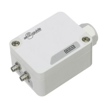
- IIoT-ready and future-proof thanks to analogue and digital signal transmission (Modbus®) as well as wireless (LoRaWAN®)
- Time-saving instrument configuration and display of current measured values on the smartphone via NFC or WIKA app
- No cabling effort for retrofit projects thanks to battery operation and LoRaWAN®
- Decentralised data node − up to four input signals − reduces cabling effort and installation costs
- Reduction of installation costs due to simple wall or DIN rail mounting in a control cabinet
 Datasheet Datasheet |

- Integrated air flow calculation based on all common formulas
- IIoT-ready and future-proof thanks to analogue and digital signal transmission (Modbus®) as well as wireless (LoRaWAN®)
- Time-saving instrument configuration and display of current measured values on the smartphone via NFC or WIKA app
- Precise measuring results, even under extreme ambient conditions
- Reduction of installation costs due to simple wall or DIN rail mounting in a control cabinet
| Datasheet |

- Decentralised PID controller – up to four input signals – reduces cabling effort and installation costs
- Integrated air flow calculation based on all common formulas
- IIoT-ready and future-proof thanks to analogue and digital signal transmission (Modbus®) as well as wireless (LoRaWAN®)
- Time-saving instrument configuration and display of current measured values on the smartphone via NFC or WIKA app
- Reduction of installation costs due to simple wall or DIN rail mounting in a control cabinet
| Datasheet |
- Dry ceramic sensor
- Smallest measuring range: 0…40 mbar
- Largest measuring range: 0…40 bar
- Accuracy ≤ 0,3%
- Robust industrial design
- Analog output: 4…20 mA, 3-wires 0…10 V, 3-wires
| Datasheet |
| User Manual |
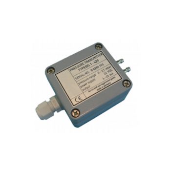
The pressure transmitters of the series IDS1-010 and IDS1-420 is for using in air and non aggressive gases. They measure difference- and absolute pressure, relative pressure and optionally velocity of flow. The analog output signal is 0-10 V or 4-20 mA. The 4-20 mA pressure transmitter is realised in two wire technic. For measurement of velocity of flow its possible to order the square root output. Because of the piezoresistive cell IDS1 reach a high reliability and precision. The dependence of zero signal from mounting position is very small. The resistance against overpressure is higher than by using other physical principles. The transmitters are housed in a robust aluminium package. This guarantees good EMC-properties. Optionally DS1 can be completed with electronic signal damping, power supply 24VAC or 230 VAC. For applications with higher pressure ranges we offer additionally to IDS1 the type IDS2.
 Datasheet Datasheet
|
The pressure transmitters of the series IDS1-010 and IDS1-420 is for using in air and non aggressive gases. They measure difference- and absolute pressure, relative pressure and optionally velocity of flow. The analog output signal is 0-10 V or 4-20 mA. The 4-20 mA pressure transmitter is realised in two wire technic. For measurement of velocity of flow its possible to order the square root output. Because of the piezoresistive cell IDS1 reach a high reliability and precision. The dependence of zero signal from mounting position is very small. The resistance against overpressure is higher than by using other physical principles. The transmitters are housed in a robust aluminium package. This guarantees good EMC-properties. Optionally DS1 can be completed with electronic signal damping, power supply 24VAC or 230 VAC. For applications with higher pressure ranges we offer additionally to IDS1 the type IDS2.
|
Datasheet
|
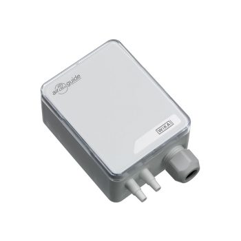
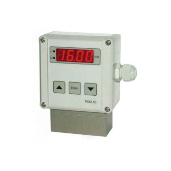
- Electrical output signal 0 ... 10 V (3-wire)
- Simple and quick mounting
- Maintenance-free
- Maximum operating pressure 20 kPa
| Datasheet |
| User Manual |
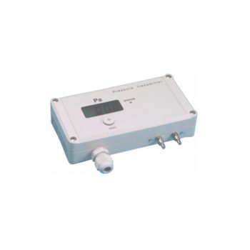
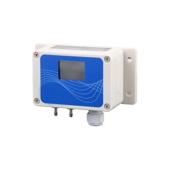
- Electrical output signal 0 ... 10 V or 4 ... 20 mA, can be selected directly at the instrument via jumpers
- Modbus® output signal (option)
- LC display (option)
- Maintenance-free
- Maximum operating pressure 20 kPa
| Datasheet |
| User Manual |
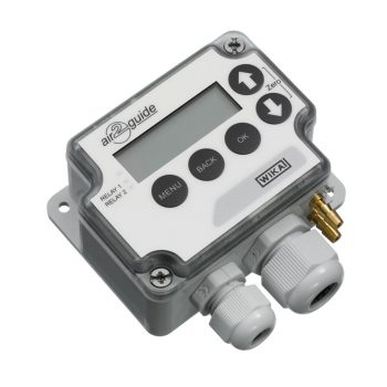
- Simple mounting
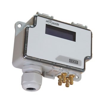
- Two differential pressure sensors in one instrument
- Two inputs for temperature sensors or analogue signal
- With Modbus® interface
- Two-line LC display for the direct reading of both pressure values
| Datasheet |
| User Manual |
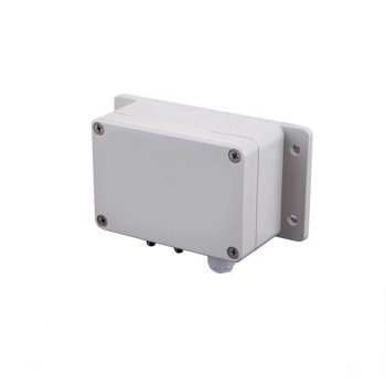
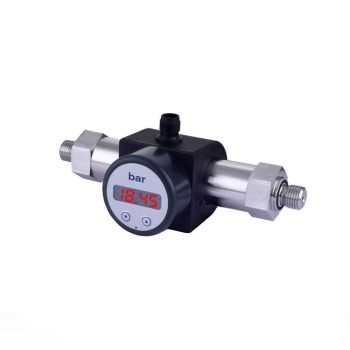
- Output signal 0 ... 10 V or 4 ... 20 mA
- Maintenance-free
- Simple operation
- High accuracy
| Datasheet |
| User Manual |
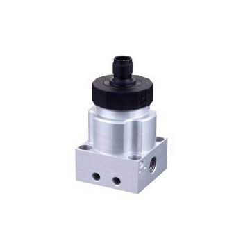
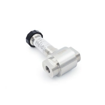
The IDM 341 is a differential pressure transmitter for non-aggressive gases and compressed air. Because of its compact and robust aluminium housing it is particularly suited for machine and plant engineering.
| Datasheet |
| Mounting instruction |
| User Manual |

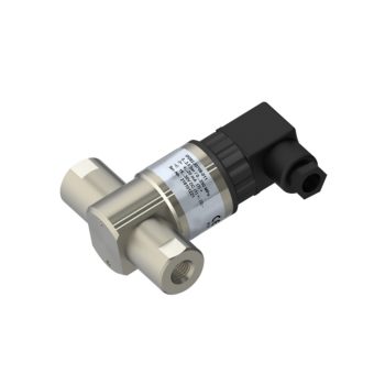
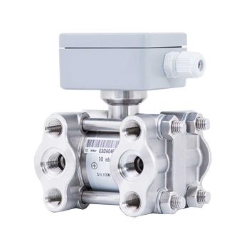
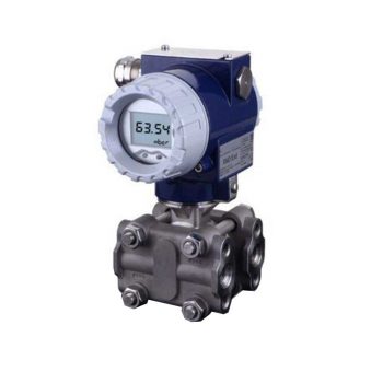
The IDM 331 is a differential pressure transmitter for industrial applications and is based on a piezoresistive stainless steel sensor, which can be pressurized on both sides with fluids or gases compatible with SST 1.4404 and 1.4435.
![]()
| Datasheet |
| Mounting instruction |
| User Manual |
- Measuring sensor with membranes made of stainless steel 1.4404
- Smallest measuring range: 0…50 mbar
- Largest measuring range: 0…25 bar
- Negative pressure measuring range: up to -25 bar
- Accuracy ≤ 0,2%
- One-sided overload capability up to 40 bar
- Rugged industrial design
- Analog output: 4…20 mA, 2-wires
0…10 V, 3-wires
|
Datasheet
|
- Measuring sensor with stainless steel membranes made of 1.4404
- Smallest measuring range: 0…50 mbar
- Largest measuring range: 0…25 bar
- Negative pressure measuring range: up to -25 bar
- Accuracy ≤ 0,2%
- One-sided overload capability up to 40 bar
- Rugged industrial design
- Analog output: 4…20 mA, 2-wires
0…10 V, 3-wires
|
Datasheet
|
|
User Manual
|
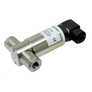
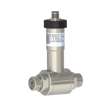
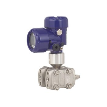
The differential pressure transmitter IDPT 100 has been especially designed for fast test processes in leakage and flow measurement, where a fast response time and high sampling rate are necessary.
|
Datasheet |
| User Manual |
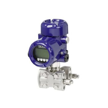
especially designed for the process industry, can be used for level measurement of closed, pressurized tanks, pump or filter controlling, etc.
![]()
| Datasheet |
| User Manual |
| User Manual (Ex) |
The differential pressure transmitter XMD has been especially designed for the process industry and can be used for level measurement of closed, pressurized tanks, pump or filter controlling, etc.
![]()
![]()
|
Datasheet
|
Process engineering | Chemical industry | Petrochemical industry
![]()
|
Datasheet
|
|
User Manual
|
|
User Manual
|
|
User Manual
|
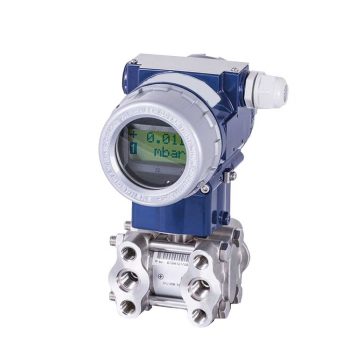
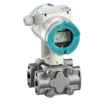
- High measurement accuracy
- Freely scalable measuring ranges
- Developed in accordance with the SIL 2 requirements
- Seven different case variants
- Configuration via DTM (Device Type Manager) in accordance with the FDT (Field Device Tool) concept (e.g. PACTware™)
| Datasheet |
| User Manual |
| User Manual |
| User Manual |
The digital pressure transmitter which features remote safety handling - developed according to IEC61508 standards for SIL2/3. Accuracy: 0,065 %
![]()
|
Datasheet
|
|
User Manual
|
The digital "high performance" pressure transmitter which features remote safety handling and is ready for digitalization - developed according to IEC61508 standards for SIL2/3. Accuracy: 0,04 %
![]()
|
Datasheet
|
|
User Manual
|
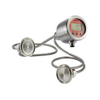
- Modulare differential pressure transmitter for diaphragm seal operation
- Various process connections with diaphragm seal technology (see product group D5)
- Wetted parts of stainless steel or special materials
- Multifunctional display with 5-segment digital display and bar graph
- Switching module with 2 floating channels, maximum 0.5 A switching current, electrically isolated to all sides, without additional auxiliary power
![]()
![]()
|
Datasheet
|
|
User Manual
|
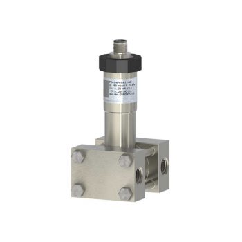
- Pressure Ranges
- 0…350 mbar diff., 40 bar abs.
- 0…1 bar diff., 40 bar abs.
- 0…3 bar diff., 40 bar abs.
- Accuracy ± 0,05 %FS
- Total Error Band -30…+ 60 °C ± 0,2 %FS
- Storage-/Operating Temperature Range -40…+ 80 °C
- Protection IP65
|
Datasheet
|
|
User Manual
|
- Dry ceramic sensor
- Ranges from 25 mbar to 60 bar
- Global errror < 0,2% F.S.
- High overload capability
- 2 adjustable switch settings
- Analog output 0(4)...20 mA or 0...10 V
| Datasheet |
